“I hereby declared that this report is a result of my own work except for the excerpts that have been cited clearly in the references.”
Signature :
Name : Tan Say Joe
BI-PEDAL WALKING ROBOT
TAN SAY JOE
This Report Is Submitted In Partial Fulfillment Of Requirement For The Degree Of Bachelor In Electrical Engineering (Control, Instrumentation & Automation )
Fakulti Kejuruteraan Elektrik Universiti Teknikal Malaysia Melaka
“I hereby declared that I have read through this report and found that it has comply the partial fulfillment for awarding the degree of Bachelor of Electrical Engineering (Control,
Instrumentation and Automation)
Signature : Supervisor’s
Name : En. Fariz Bin Ali @ Ibrahim
ACKNOWLEDGEMENT
ABSTRAK
ABSTRACT
TABLE OF CONTENTS
CHAPTER CONTENTS PAGE
ACKNOWLEDGEMENT iv
ABSTRACT v
TABLE LIST x
FIGURE LIST xi
1 INTRODUCTION
1.1 Introduction 1
1.2 What is a robot
1.2.1 Application of Robot 2
1.3 Project Objective 3
1.4 Project Scope 4
1.5 Problem Statement 5
1.6 Project Planning Schedule (Gantt chart) 6
2 LITERATURE REVIEW
2.1 INTRODUCTION 7
2.1.1 KHR-2HV Humanoid Robot 8 2.1.1.1 How did this product contribute
to the project? 9
2.1.2 Toddler Robot 10
2.1.2.1 How did this product contribute
to the project? 11
2.1.3 A Bipedal Walking Robot With
Efficient And Human-Like Gait 12 2.1.3.1How did this paper contribute
3 THEORY AND PROJECT BACKGROUND
3.1 Introduction 14
3.2 Background Study of Bi-Pedal walking
Robot/ Humanoid Robot 14
3.3 Microcontroller 15
3.3.1 Why Use Microcontroller? 16 3.3.2 Overview of microcontroller from
Microchip 18
3.3.3 Why Use PIC16F877A Microcontroller? 19 3.3.4 Microcontroller basic circuit 24
3.4 Motor driver: L293b 26
3.4.1 Application of L293b 27
3.5 Voltage Regulator: LM7805 28
3.6 Motor 28
3.6.1 DC Motor 29
3.6.2 Servo Motor 30
3.6.3 Stepper Motor 32
3.6.4 Motor Types: An Overview 34 3.6.5 Why Choose Twin gearbox DC Motor 36
4 METHODOLOGY
4.1 Introduction 37
4.2 Project Methodology 38
4.3 Block Diagram 40
4.4 Hardware Development 40
4.4.1 Circuit of PIC16F877A Microcontroller 41
4.4.1.1 Port Assignment 42
4.4.2 PIC USB PROGRAMMER 43
4.4.3 Power supply 45
4.4.4 Circuit of Microcontroller Power Supply 46 4.5 Software Development
4.5.1.1 How to develop a program in
MicroC 48
4.6 PIC Basic Circuit testing with LED blinking 51
4.6.1 LED blinking program 52
5 FINAL RESULT
5.1 INTRODUCTION 54
5.2 Electrical and Software Part
5.2.1 Programmer 55
5.2.2 Microcontroller Board 56
5.2.3 Motor Driver 57
5.2.4 Programming/ Coding 58
5.3 Material and Mechanical Part 59
5.4 Design that have been tried 64
6 CONCLUSION AND DISCUSSION
6.1 Introduction 66
6.2 Conclusion 66
6.3 Discussion and Recommendation 67
REFERENCES 68
TABLE LIST
NO TITLE PAGE
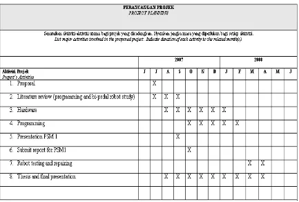
1 Table 1.1: Gantt chart 6
2 Table 3.1: Comparision between microcontroller 17 3 Table 3.2: Features and main pin of PIC 16F877 20 4 Table 3.3: PIC model number and their meanings 21 5 Table 3.4: Pin location and number of I/O for
port A, B, C, D and E 21
6 Table 3.5: Mode of Clock Oscillators 22
7 Table 3.6: Comparing Features of Robot’s Motor Types 35
FIGURE LIST
NO TITLE PAGE
1 Figure 1.1: Comparison between human and robot 2
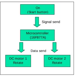
2 Figure 1.2: Flow chat for motor control 4
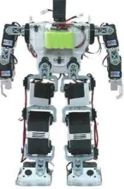
3 Figure 2.1: KHR-2HV Humanoid Robot 8
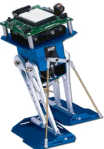
4 Figure 2.2: Toddler Robot 10
5 Figure 2.3: Bi-pedal walking robot with efficient and
Human-like gait. 12
6 Figure 3.1: Microcontroller-Based System 15
7 Figure 3.2: Some of the PIC16Fxxx family 18
8 Figure3.3: PIC16F877 overview 19
9 Figure 3.4: PIC17F877A Input output pin 20
10 Figure 3.5: Crystal Connection 22
11 Figure 3.6: Ceramic resonator with build-in capacitors 23
12 Figure 3.7: RC Oscillator Connection. 23
13 Figure 3.8: PIC Basic Circuit 24
14 Figure 3.9: Prototype of PIC16F877A basic circuit that
built on bread board 25
15 Figure 3.10: Motor driver L293b 26
16 Figure3.11: Single directional DC motor control 27
17 Figure 3.12: Bidirectional DC motor control 27
18 Figure 3.13: Voltage regulator 28
19 Figure 3.14: DC Motor 29
20 Figure 3.15: Process of DC motor rotating 30
21 Figure 3.16: Servo motor 30
22 Figure 3.17: The Desired Position of Servo Motor 31
23 Figure 3.18: Stepper Motor 32
[image:12.612.118.526.138.714.2]25 Figure3.20: Operation of Stepper Motor: Step 2 33
26 Figure 3.21: Operation of Stepper Motor: Step 3 33 27 Figure 3.22: Operation of Stepper Motor: Step 4 34 28 Figure 3.23: Tamiya Twin Motor gearbox with DC motor 36
29 Figure 4.1: Methodology flow chart 38
30 Figure 4.2: Block diagram of the robot system 40
31 Figure 4.3: Hardware block diagram 40
32 Figure 4.4: Pin diagram of Microcontroller PIC16F877A 41 33 Figure 4.5: Basic PIC of Microcontroller interface to motors 41
34 Figure 4.6: USB PIC programmer circuit. 43
35 Figure 4.7: USB PIC programmer 43
36 Figure 4.8: Block diagram of 5V Power Supply to Microcontroller 45 37 Figure 4.9: Block diagram of 9V power supply to DC motor 45
38 Figure 4.10: 9V battery 45
39 Figure 4.11: 4.5V battery 45
40 Figure 4.12: 5V power supply circuit for Microcontroller 46 41 Figure 4.13: Figure of where to create a new project in MicroC 48
42 Figure 4.14: of the setting 49
43 Figure 4.15: How the code is written and the error indication 49 44 Figure 4.16: How the code is written and the success indication 50 45 Figure 4.17: The HEX code that shown in WinPic800 50 46 Figure 4.18: Program has been successfully burn into
the PIC 16F877A 51
47 Figure 4.19: Schematic diagram for LED blinking 51
48 Figure 4.20: LED is “OFF” 52
49 Figure 4.21: After one second LED is “ON” 52
50 Figure 4.22: Code for LED blinking 52
51 Figure 4.23: Indication of output signal port 53 52 Figure 4.24: Indication of input signal port 53 53 Figure 5.1: Programmer PIC has been constructed on the
[image:13.612.116.526.89.730.2]54 Figure 5.2: Layout of the programmer circuit 55
55 Figure 5.3: USB programmer connection layout 56
56 Figure 5.4: Microcontroller board 56
57 Figure 5.5: Motor driver circuit 57
58 Figure 5.6: Bi-pedal walking robot coding 58
59 Figure 5.7: Materials and tools that used 59
60 Figure 5.8: Robot moving forward 60
61 Figure 5.9: Robot moving forward 60
62 Figure 5.10: Robot moving to left 60
63 Figure 5.11: Robot moving right 61
64 Figure 5.12: Mounting of the Tamiya twin-motor gear box 61 65 Figure 5.13: The upper part of the robot 62 66
Figure 5.14: Aluminium with sliding hole 62
67 Figure 5.15: Front view of the robot 62
68 Figure 5.16: Back view of the robot 63
69 Figure 5.17: Side view of the robot 63
70 Figure 5.18: Top view of the robot 63
71 Figure 5.19: First mechanical design 64
72 Figure 5.20: Second mechanical design 64
73 Figure 5.21: Third mechanical design 65
[image:14.612.112.533.56.612.2]CHAPTER 1
INTRODUCTION
1.1 Introduction
In this chapter robot will be the main discussion topic. What is robot? What is autonomous robot? Beside that, the objective of the project, scope of the project and also the problem statement of the project will also be presented in this chapter. All these will be discuss in more detail in the sub-topic 1.2, 1.3, 1.4 and 1.5 below.
1.2 What is a robot?
According to Robot Institute of America (1979):
“A robot is a reprogrammable, multifunctional manipulator designed to move material, parts, tools, or specialized devices through various programmed motions for the performance of a variety of tasks”[1].
According to Webster dictionary:
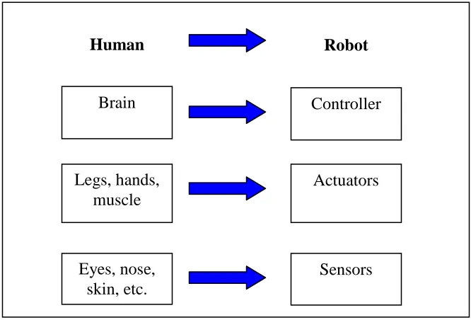
Generally, robots have three main parts known as processor, sensor, and motor control system. There are quite similar when compare human with robot, just the mechanism is different. Sensor of the robot can represent eyes of human, while actuators represent the legs of human and controller as the brain of human.
[image:16.612.184.517.185.411.2]
Figure 1.1: Comparison between human and robot
1.2.1 Application of Robot
Robot can replace human’s job in industry because robot can do many things faster than humans. Robots do not need to be paid, eat, drink, or go to the bathroom like human. They can do repetitive work that is absolutely boring to human and they will not stop, slow down, or fall asleep like human.
Individual stationary sensors have limited ranges and applications. Watchdogs or human can lose their level of alertness during a shift or can easily be injured by an intruder. Autonomous robot systems are tools which combine the precision of sensors
with the mobility and intelligence of humans. Robotic site security sentries are able to work long hours at a consistently high level of precision and vigilance.
Nowaday, doctors have to use a robot instead when operating. A human would not be able to make a hole exactly one 100th of a inch wide and long. When making medicines, robots can do the job much faster and more accurately and delicate than a human. Some doctors and engineers are developing prosthetic (bionic) limbs by using robotic mechanisms.
People are interested in places that are sometimes full of danger, like outer space, or the deep ocean. Thus, when they cannot go there themselves, they make robots which are able to go there for exploration. The robots are able to carry cameras and others instruments so that they can collect information and send it back to their human operators. The continuing development of autonomous robot technologies furthers our abilities to explore the universe.
Beside that, robot can be applied in military operations to reduce the number of casualties which occur during military actions. The military also uses robots for locating and destroying mines on land and in water, entering enemy bases to gather information and spying on enemy troops.
1.3 Project Objective:
The objectives of this project are:
1. To build a robot which can move in forward, backward, turn left and turn right direction.
2. Build a robot that can be in stable condition when it was walking or turning either to left or right side.
1.4 Project Scope
The scope of this project is to build a bi-pedal walking robot that is able to perform tasks such as walking in forward position, backward position, turn left and also turn right. The signal of the movement will be sent by microcontroller 16F877A to the DC motor. This signal will control the speed of the motor and also will decide which motor will rotate first. MicroC will be used to write the program and also be the compiler to change the C language into hex file language. Besides that Proteus 6.0 is used as simulation software for the program that has been written to make sure the program or coding that had been write are up to expectation.
For the mechanical part of the robot, aluminium is used as the main material for the whole robot, because aluminium is light weighted and easy to be drill if any drilling needed compare to other material such as metal or standard steel. Other materials that been use are various size of screws and also the stripboard of the microcontroller board and motor driver board act as the support for the body.
On (Start button)
DC motor 2 Rotate DC motor 1
Rotate
Microcontroller (16F877A)
Signal send
[image:18.612.197.454.409.672.2]Data send
From the flow chart above, the whole robot system can be view easily. First when the robot start button is on there will be voltage to activate the microcontroller when the microcontroller is activated signal will be send to the motor 1 and motor 2. Which motor will be rotated first are depend on how the program is written.
1.5 Problem Statement
1.6 Project Planning Schedule (Gantt chart)
CHAPTER 2
LITERATURE REVIEW
2.1 Introduction
Study on the similar project or product that on the market is very helpful to give a brief expression on how to make a good bi-pedal walking robot project. The source can be getting from internet or any reference such as magazine or books. The mechanism of the robot can be learned easily by refer to similar robot especially for electrical student who have less knowledge regarding mechanical part.
2.1.1 Case Study 1: KHR-2HV Humanoid Robot
Figure 2.1: KHR-2HV Humanoid Robot
2.1.1.1 How did this product contribute to the project?
2.1.2 Case study 2: Toddler Robot
Figure 2.2: Toddler Robot
The Toddler robot is a two-servo bipedal robot controlled by an embedded BASIC Stamp® 2 microcontroller that stands 10" tall. This is a high-quality machined kit made from aluminum and brass metals [4]. This toddler robot is a very good learning kit for student to learn the basics of embedded control. This robot has the ability to walk straight and turn. This walking robot shifts its center of gravity to walk and turns by sliding its feet in opposite directions. Other than that, it can follow or avoid light, avoid or seek objects using infrared light reflection. It can be interface with digital, resistive, and frequency sensors which can be decide.
The Toddler is controlled by a surface mounted BASIC Stamp 2 module. Four infrared sensors and receivers, LEDs, servos for tilt and stride, resistors/capacitors, speaker, photoresistors complete the control system. [4]:
o Dimensions (inches) 1.38x0.67x1.26 o Weight 26.6g
o Speed (sec/60o) - 0.19 o Torque (oz-in) – 47 [5]