DESIGN WIDEBAND MICROSTRIP ANTENNA USING GRAPHENE
ZETTY ZURAIDA BINTI SAHARUDIN
This Report Is Submitted In Partial Of Requirements For The Bachelor Degree of Electronic Engineering (Telecommunication Electronics) With Honours
Fakulti Kejuruteraan Elektronik dan Kejuruteraan Komputer
Universiti Teknikal Malaysia Melaka
ii
UNIVERSTI TEKNIKAL MALAYSIA MELAKA
FAKULTI KEJURUTERAAN ELEKTRONIK DAN KEJURUTERAAN KOMPUTER
BORANG PENGESAHAN STATUS LAPORAN
PROJEK SARJANA MUDA II
Tajuk Projek : DESIGN WIDEBAND MICROSTRIP ANTENNA USING GRAPHENE
Sesi
Pengajian : 1 2 / 1 3
Saya ZETTY ZURAIDA BINTI SAHARUDIN mengaku membenarkan Laporan Projek Sarjana Muda ini disimpan di Perpustakaan dengan syarat-syarat kegunaan seperti berikut:
1. Laporan adalah hakmilik Universiti Teknikal Malaysia Melaka.
2. Perpustakaan dibenarkan membuat salinan untuk tujuan pengajian sahaja.
3. Perpustakaan dibenarkan membuat salinan laporan ini sebagai bahan pertukaran antara institusi
pengajian tinggi.
4. Sila tandakan ( √ ) :
SULIT*
*(Mengandungi maklumat yang berdarjah keselamatan atau kepentingan Malaysia seperti yang termaktub di dalam AKTA RAHSIA RASMI 1972)
TERHAD** **(Mengandungi maklumat terhad yang telah ditentukan oleh organisasi/badan di mana penyelidikan dijalankan)
TIDAK TERHAD
Disahkan oleh:
__________________________ ___________________________________
(TANDATANGAN PENULIS) (COP DAN TANDATANGAN PENYELIA)
iii
“I hereby declare that this report is the result of my own work except for quotes as cited in the references”
Signature : ... Author’s name : ZETTY ZURAIDA BINTI SAHARUDIN
iv
“I hereby declare that I have read this report and in my opinion this report is sufficient in terms of the scope and the quality for the award of Bachelor of
Electronic Engineering (Telecommunication Electronics) With Honours”
Signature :... Supervisor’s Name : AZMAN BIN AWANG TEH
v
vi
ACKNOWLEDGEMENT
vii
ABSTRACT
viii
ABSTRAK
ix
TABLE OF CONTENTS
CHAPTER TITLE PAGE(S)
PROJECT TITLE i
DECLRATION ii-iv DEDICATION v
ACKNOWLEDGEMENT vi
ABSTRACT vii
ABSTRAK viii
TABLE OF CONTENTS ix-xii LIST OF FIGURES xiii-xiv LIST OF TABLES xiv
I INTRODUCTION 1
1.1 INTRODUCTION 1
1.2 PROJECT OBJECTIVES 2
1.3 PROBLEM STATEMENT 2
1.4 SCOPE OF WORK 3
1.5 METHODOLOGY 3
x
II LITERATURE REVIEW 6
2.1 INTRODUCTION 6
2.2 INTRODUCTION OF ANTENNA 6-7 2.3 MICROSTRIP PATCH ANTENNA BASICS 8-10 2.3.1 Basic Characteristic of Microstrip Antenna 11-12 2.3.2 Rectangular Patch Antenna 12-14 2.4 FEED TECHNIQUES 14-15 2.4.1 Microstrip Line Feed 15
2.4.2 Coaxial Feed 16
2.4.3 Aperture Coupled Feed 17
2.4.4 Proximity Coupled Feed 18
2.4.5 Coplanar Waveguide (CPW) feed 18-19 2.5 PRINTED SLOT ANTENNAS 19-20 2.6 GRAPHENE MATERIAL PROPERTIES 21
2.6.1 Chemical Properties 21
2.6.2 Mechanical and Thermal Properties 22
2.6.3 Comparison with copper and gold materials 22-23 2.6.4 Producing Graphene 23-24 III METHODOLOGY 25
3.1 INTRODUCTION 25
3.2 MICROSTRIP ANTENNA WITH DOUBLE U-SLOT 25
xi
3.2.1 Design Specification 25-26
3.2.2 Designs by Calculation 26-27
3.2.3 Design Structure and Parameter Dimension 27-29
3.3 SIMULATION PROCESS 29-33
VI RESULT ANALYSIS AND DISCUSSIONS 34
4.1 INTRODUCTION 34
4.2 SIMULATION RESULT AND ANALYSIS 34
4.2.1 Wideband Microstrip Antenna with 34-37
double u-slot using Copper as patch material
4.2.2 Wideband Microstrip Antenna with double 37-39
u-slot using Graphene as patch material
4.2.3 Wideband Microstrip Antenna with double 39-42
u-slot using Gold as patch material
4.2.4 Combination of three graph return loss of 42-43
copper, graphene and gold patch antenna
4.2.5 Summary of three different patch materials 43-44
4.3 PARAMETRIC STUDY 44-47
V CONCLUSION AND FUTURE WORK 48
xii
5.2 FUTURE WORK 49-50
REFERENCES 51-53
xiii
LIST OF FIGURES
NO TITLE PAGE(S)
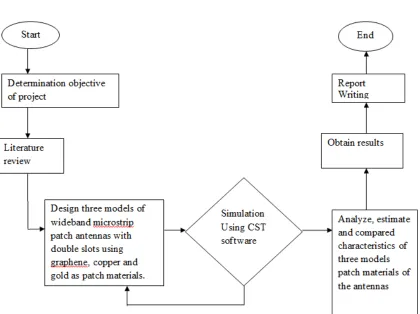
1.1 Flow chart of project 1
2.1 Antenna Basic Operation 8
2.2 Microstrip Antenna Configuration 9
2.3 Basic shape of microstrip antennas 10
2.4 Basic configuration of Microstrip antenna 11
2.5 Rectangular Microstrip Patch Geometry 12-13 2.6 Rectangular patch antenna 13
2.7 Microstrip Line Feed 15
2.8 Coaxial Feed Microstrip Patch Antenna 16
2.9 Aperture-coupled feed 17
2.10 Proximity-coupled Feed 18
2.11 CPW Feeding Techniques: (a) Inductive feed termination 19
(b) Capacitive feed termination 2.12 Various shape of slot antenna 20
2.13 Making graphene 23-24 3.1 Front View 27
3.2 Bottom View 28
3.3 Side View 28
xiv
3.5 Patch plane setup 31
3.6 Coaxial probe feed structure 31-32 3.7 Boundary condition setting 32
3.8 Monitor setting 33
4.1 Graph of return loss for copper patch antenna 35
4.2 Directivity for copper patch antenna 35
4.3 Gain for copper patch antenna 36
4.4 Input impedances for copper patch antenna 36-37 4.5 Graph of return loss for graphene patch antenna 37
4.6 Directivity for graphene patch antenna 38
4.7 Gain for graphene patch antenna 38
4.8 Input impedances for graphene patch antenna 39
4.9 Graph of return loss for graphene patch antenna 40
4.10 Directivity for gold patch antenna 40-41 4.11 Gain for gold patch antenna 41
4.12 Input impedances for gold patch antenna 42
4.13 Combination graph of return loss 42
4.14 The changes of length of u-slot, E2 44
4.15 The changes of thickness of substrate, t1 45
4.16 The changes of length of ground, A 46
xv
LIST OF TABLES
NO TITLE PAGE(S)
CHAPTER I
INTRODUCTIONS
1.1 Introduction
2
copper, gold and graphene for patch antenna are applied and compared to see the different results which to improve the bandwidth.
1.2 Project Objectives
The objective of this project is to design a wideband microstrip patch antenna using graphene as patch antenna. This will used structural technique to increase the bandwidth of the antenna . Besides, the input impedances and radiation pattern is simulate in Computer Simulation Technology (CST) in order to get the result. Furthermore, the microstrip antenna’s characteristics are analyzed for three different types of material. The comparison between copper, graphene and gold patch antennas will be shown. It is then followed by a parametric study for antenna design to achieve wideband frequency and also explanation about the design of antenna have been made will discuss later on.
1.3 Problem Statement
3
the mobile phone market. So, it is importance to create a new invention of microstrip antenna for better performance in electromagnetic waves field.
1.4 Scope of Work
This project first involves designing wideband microstrip antenna using graphene. Then construct three models of microstrip antenna using graphene, copper and gold of patch antenna. The stimulation part is carried out using Computer Simulation Technology (CST) to simulate the input impedance and radiation pattern of antenna. The results from simulation are analyze, estimate and compared for three different patch antenna materials. Other antenna parameters such as its return loss level, gain and radiation pattern also will be considered for antenna design.
1.5 Methodology
4
estimation of the characteristic of the antennas will be carried out. All experimental result will be included in the final report.
[image:19.612.119.539.167.481.2]
Figure 1.1: Flow chart of project
1.6 Chapter Review
5
Chapter II describes the introductions to the antenna and microstrip antenna is presented. This chapter will explain the basic concept of the antenna. Then the introduction of the microstrip patched antenna concept and design will be introduced. This chapter also gives the information about comparison of chemical properties among graphene, copper and gold materials. Besides, the issues of the materials uses will be discusss on this project.
Chapter III presents the methodology used or the design process in this project. The methodology involves the procedures of gathering information data regarding to the antenna design. This section also explains about the optimization process involved in this project.
Chapter IV presents the results achieved in this project. This results involve the parametric study of antenna, the comparison between graphene, copper and gold of patch antenna, the theoretical and simulated result are also shown in this chapter.
6
CHAPTER II
LITERATURE REVIEW
2.1 Introduction
This chapter will briefly explain the basic concept of the antenna. Then the introduction of the microstrip patched antenna concept and design will be introduced. This chapter also gives the information about graphene, copper and gold material’s properties which to compare among them to use as patch antenna in this antenna design project.
7
An antenna is to encourage electrical signals to reach large distances from the antenna which means by to radiate. The IEEE standard defines an antenna as “that part of a transmitting or receiving system that is designed to radiate or to receive electromagnetic”[1].
Antenna also as a receiver of electromagnetic energy which look as the transition region between free-space and a guiding structure as transmission line. The guiding structure transports electromagnetic energy to or from the antenna [2].
An antenna is transducer, an impedance matching device, a radiator and a sensor of electromagnetic waves. It is an essential device/element in all types of communication and radar systems. It can be considered as a source of electromagnetic waves[3].
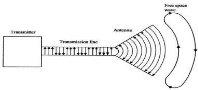
The transmission line in the wireless communication is not wiring transformation line, but free space. The flow of charge through a conductor represent as the electrical signal is transmitted through the antenna. The charge cannot pass through a non-conductor (free-space). However, the electromagnetic wave cannot pass through a conductor and proceeds by forming the magnetic field on a non-conductor.
8
Figure 2.1: Antenna Basic Operation
Antenna is important in communication nowadays. Antenna is important device for transmitting and receiving the signal. The signal cannot pass through free-space just like that but must have a device to done the task which is antenna.
Antenna widely used in wireless communication. Wireless local area network (WLAN) is one of application that used antenna. WLAN used in wireless communication for home settings and in commercial. For example, in airports, coffee shops, other public spaces and many companies offer WLAN access [4].
Antenna consists of various types. The types of antenna are wire antennas, aperture antennas, microstrip antennas, array antennas, reflector antennas and lens antenna. For WLAN application, microstrip antenna is more preferable.
2.3 Microstrip Patch Antennas Basic
9
Grieg and Englemann [5]. The earliest known realization of a microstrip like antenna integrated with microstrip transmission line was developed in 1953 by Deschamps [6].
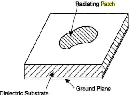
[image:24.612.194.424.247.412.2]As shown figure 2.2, a microstrip antenna in its simplest configuration consists of a radiating patch on one side of a dielectric substrate ( which has a ground plane on the other side. This is to enhance the fringe fileds that account for the radiation. However, other performance requirements may dictate the use of substrate materials whose dielectric constants can be greater than[7].
Figure 2.2: Microstrip Antenna Configuration