DOI: 10.12928/TELKOMNIKA.v13i2.980 563
A New Method of Trajectory Restoration at Intersection
Zheng Ke*1,2, Song Xiangbo3, Zhu Dunyao1,3
1
Intelligent Transport Systems Research Center ,Wuhan University of Technology, Wuhan 430063, China
2
School of Computer and Information Engineering, Nanyang Institute of Technology, Nanyang 473004, China
3
Wuhan KOTEI Informatics Co., LTD., Wuhan 430074, China *Corresponding author, e-mail: [email protected]
Abstract
Floating car data (FCD) is vechiel’s position trace that is comes from Global Positioning System receivers.collected at the discrete time. FCD contains much information of traffic and road-network. But there are different level of trajectory shape damages because of the affection of sample frequency and running speed. So before the FCD mining, the first thing should be done is to restore track to make up for the loss. This paper analyzes the spatial-temporal characteristics of floating car trajectory at intersection, and builds an error recognition model and an adjustment algorithm. Experiments showed that this method can improve accuracy of trajectory restoration and its performance is better than existing method. Thus, the proposed method is practical for further data mining.
Keywords: floating car data, trajectory restoration, intersection, spatial-temporal characteristics
1. Introduction
Floating Car refers to the moving car on the road with a variety of sensors, which can periodically collect information such as its position, velocity and direction. The car spatial and driving information is called Floating Car Data or FCD for short. Floating car like mobile sensors distributed in road network [1] to capture the traffic information (such as congestion, transport road speed) in current time. FCD has become one of the key technologies in the field of intelligent transportation, which is widely used in the current-time traffic surveillance and traffic management. Compared with other methods of traffic information collection, FCD has the advantages of low cost, high coverage, and strong real-time capability. On the other hand, the track of car outlines the road topology of an area [2], so FCD is also used as to extract and update the urban road information [3].
FCD is collected at the discrete time points. Sampling interval and the vehicle speed will lead to the random loss of track [4]. So before the FCD mining, the first thing should be done is to restore track to make up for the loss. There are two ways in track restoration, one is matching the track to the road on the map, and the other is fusing multiple trajectories from the same path. But this loss will cause the position deviation of intersection when multiple tracks fusing. The fusion error must be recognized and repaired in order to improve the accuracy of trajectory restoration, and classify track information effectively.
Currently, the mining based FCD is mainly used to get traffic information and road network information. The system generally consists of four levels: Track Collection and Store, Track Registration, Information Mining and Applications. Track Registration means to restore or repair the loss shape of track caused by collection frequency and vehicle speed. There are two kinds of track registration method, one is Map Matching, and another is Multi-track Fusion [5],[6].
tracks, the literature [2],[10]-[12] suggest that clustering algorithm may use the spatial distance between the trajectory points to measure whether the track is from the same road, and the literature [13]-[16] suggest that the shape of the trajectory may use as the similarity metric to identify a road on the same track.
Whether the clustering algorithm is point-based or curve-based, the trajectory shape after fusing is depend on the frequency sampling and the vehicle speed. At Crossroad and T-junction, as the impact of traffic regulation and driving habits, fewer track points can be collected at the intersection, and it will result in that trajectory integration which is gained by the trajectory fusion algorithm deviates from the actual location.
To improve the accuracy of track restoration, it need to identify and adjust such error. The literature [3] borrows the concept of a snake from the domain of image processing, and computes an approximation for the intersection point using a simple star-shaped contour suffices. In this paper, we present a recognition model and give an adjustment algorithm for this fusion error based on the spatial-temporal characteristics of trajectory at intersection. We have analyzed the spatial-temporal characteristics of the car trajectory at the intersection with the intersection geometry and the vehicle status variation, and built an error recognition model and a restoration algorithm for crossing position deviation that is generated by the trajectory fusion.
2. Research Method
The purpose of track registration is to restore the vehicle actual traveling path, the shape of these tracks corresponding to the road shape. Therefore, fusing a plurality of tracks that come from the same road can be obtained the road network topology. There are some related terms by the following definition:
Definition 1. SHAPE_POINT, the point that represents the road shape and in this paper can be approximate understood as the sampling points of trajectory. Each SHAPE_POINT include much information, such as position, speed, and direction etc.
Definition 2. NODE, a special node objects that is made up in order to express road network topology and can be understood as an actual intersection.
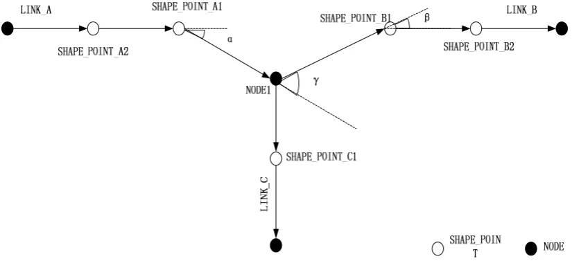
Definition 3. LINK, a curve with direction means the passageway between NODES. A LINK is composed of two NODES (START NODE and END NODE) and some SHAPE_POINTS, namely, it is a collection of dots. It can be understood as a road that connects two NODES. A LINK is referred as EXIT LINK when the connected NODE is a START NODE, and called ENTER LINK when the connected NODE is an END NODE. Figure 1 shows the floating car trajectory around node. If we consider NODE_1 as the target node, LINK_A is ENTER LINK; meanwhile, LINK_B and LINK_C are EXIT LINK.
Definition 4. DIRECTION ANGLE when vehicle enters into a NODE. That is the change of track direction at the nearest SHAPE_POINT of ENTER LINK to a NODE.As shown in Figure 1, SHAPE_POINT A1 and A2 form a vector,at same time SHAPE_POINT A2 and NODE1 also form a vector, the vector angle is the DIRECTION ANGLE of LINK_A into NODE1.
Definition 5. The vehicle’s direction angle when it leaves point NODE, which is an angle variety after the beginning NODE at the SHAPE POINT when the vehicle departs from LINK. Just as Figure 1 has shown, the point NODE and SHAPE_POINT_B1 form an vector, SHAPE_POINT_B1 and SHAPE_POINT_B2 form another vector, the intersection angle β is the shape angle when the vehicle leaves point NODE.
Definition 6. The vehicle’s direction angle at point NODE is the angle variety when the vehicle enters point NODE and departs from LINK. As Figure 1 shown, SHAPE_POINT_A1, the nearest point from NODE1 after the vehicle enters LINK_A, and NODE1 form an vector. And SHAPE_POINT_B1, the nearest shape point from NODE1 after the vehicle departs from LINK_B, and NODE1 form another vector, the two vectors intersection angle is the vehicle’s direction angle at point NODE.
Definition 7. One vehicle enters LINK and the other departs from LINK at the point NODE, which form a pair of LINKS. To each pair of LINKS, link the two shape points that close to the point NODE mostly besides point NODE itself to form a curve. And define the angle to measure the smooth degrss of the curve. Figure 2 shows the amplifying trajectory around node.
Figure 2. The amplifying trajectory around NODE
Taking two shape points that enter LINK and near the endpoint to form a vector, and then taking two shape points that depart from LINK and near the start point NODE to form another vector. The direction angle of the two vectors is angle θ. As Figure 2 shown, angle θ is the intersection angle of vectors which are formed from SHAPE_POINT_A2 to SHAPE_POINT_A1 and SHAPE_POINT_B1to SHAPE_POINT_B2. Taking two shape points that enter LINK and near the endpoint to form a vector, and then taking two shape points that enter LINK then depart from LINK and near start point NODE to form an another vector. The direction angle of two vectors is angle δ. As Figure 2 shown, angle δ is the intersection angle of two vectors that are formed from SHAPE_POINT_A2 to SHAPE_POINT_A1 and from SHAPE_POINT_A1 to SHAPE_POINT_B1. The larger one of angle θ and angle δ can represent the smooth degree of the LINKS as
ax( ,
)
M
(1)When the vehicle turns at the intersection, because of the affection of sample interval, vehicle speed and direction, the sampling site rarely appears at the intersection. On shape recognition or clustering algorithm of floating car trajectory and reduction of roads and intersections, due to there are less trajectories at the intersections, may lead to deviation of intersection position and actual position after fusion.
The position deviation mainly appears at the intersections which exist the pairs of LINKS that near the liner. So in repair of the NODE position , we should depend on these pairs of LINKS. If there is deviation of NODE after the trajectory fusion, then the deviation possesses the following features.
Spatial-temporal Characteristic 1: After eliminating the point NODE, the position deviation of the point NODE is produced by the turning of the vehicle, according to which, we should not take the trajectory that appears at the vehicle turning into account when we are doing the position repair. That is to say, we should miss the intersection angle when it became closely to a right angle that enters and departs from the pair of LINKS.
Spatial-temporal Characteristic 2: According to the rule of the vehicle motion state, we can know that if the vehicle does not turn at the intersection, then the angle of the vehicle satisfies the angle change rule, that is, if the vehicle driving along a straight line into the intersection and it changes its direction, then it will change its direction and back to the straight line again when it departs from the intersection.
Spatial-temporal Characteristic 3: The trajectory that be produced by the vehicle passes the intersection must have angle change when it departs the point NODE if the angle changes when it enters the point NODE.
Hence, we can decide whether there is a deviation of the point NODE on the basis of the motion trajectory characteristic on the straight line at the intersection of the vehicle. That means we can decide whether we need to do the position repair on the basis of the specific condition of LINK: (1) If the point NODE only connects with one LINK, then the point NODE cannot recognize the position error; (2) i1f the point NODE connects with several LINKS, and all of them are belong to the same pattern that either they enter LINK or depart from LINK, or then the grouping does not need to repair the point NODE; (3) If the point NODE connects with several LINKS, and some of them enter LINK and the other depart from LINK, then we should do further judgment with each LINK.
The point NODE which has been repaired should guarantee the straight line that near it is the smoothest one. So we should find out the smoothest pair of LINKS before do the position repair of the point NODE. And the selection criteria of the most smooth pair of LINKS as follows:
(1) If there is only one pair that enters and departs from the LINKS, then the pair of LINKS is the smoothest one.
Figure 3. Restore the NODE position
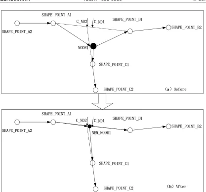
Choosing two shape points that near the point NODE mostly from the most smooth pair of LINKS to form an segment, and that segment is the position repair standard segment of the point NODE. The new point NODE should be in this standard segment. As shown in Figure 3(a), the shape point SHAPE_POINT_A1 and SHAPE_POINT_B1 form an segment is the standard segment.
At the range of standard segment, choosing new point NODE from the alternative positions on the basis of specific condition that the vehicle enters and departs from the pair of LINKS.
(1) Calculating the midpoint as the first alternative position of the point NODE, as the point C_ND1 in Figure 3(a).
Figure 4. The candidate position
If the intersection in the standard segment, then we will take the segment from calculating as the alternative position, as the point C_ND2 in Figure 3 and C_ND2 in Figure 4(a).
If the intersection is not in the standard segment, we will choose the endpoint of the segment that near the intersection as the alternative position of point NODE the mid intersection INTE_POINT is not in the standard segment, so we will choose the nearer endpoint SHAPE_POINT_A1 as the alternative position of the point NODE.
(3) Taking all the alternative position points into the alternative collection in turn. We can easily find out that, all the alternative NODE are in the standard segment, either are the endpoint of the standard segment or the intersection of the segment, and there are same coordinate value in the alternative position points.
3. Experiments and the Analysis
The experiment data is provided by Wuhan Kotei Informatics CO., LTD. The floating trajectory has been gathered for two months and the collection area was about 400,000 square kilometer. The trajectory collection frequency is 1/30 HZ and the GPS accuracy is 10-6 latitude and longitude. The data includes time, position, road range and the Parcel ID.
The program is aimed to use the original trajectory data to extract the area road network topology, but the specific algorithm is not been elaborated in this thesis which is been replaced by simple introduction. Algorithm process: first to delete the abnormal trajectory point and then split the trajectory on the basis of the parcel that includes trajectory, the road range and the intervals between the trajectory points. Taking the parcel as an unit and according to the trajectory curve similarity to recognize the similarity of the trajectories and blending them ,from which we can get a temporary road network topology and there are 1 ,898 ,000 points of NODE.
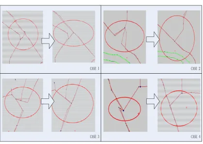
The experiment applies the above model to recognize and repair these NODES. And the NODES that after repair will be contrasted with the contemporary NODES position in the practical map.
Figure 5. The experimental result of some typical case
To highlight the performance of the proposed method, we compared the proposed method with [3]. Table 1 lists the comparison results.
Table 1. The experimental results.
Method Total Point
Recognized point
correct repaired
error repaired
correct recognition rate
improvement rate The proposed
method 1898113 146432 106324 40108 72.6% 5.60% Method in [3] 128526 74223 54303 57.7% 3.91%
It can be seen in table 1 that the correct recognition rate of the proposed method in this paper is better than the method in [3] by 14.9% and the improvement is 1.59% higher. The comparison indicates that the proposed method provides better performance than existing method onwing to the consideration of spatial-temporal characteristics of floating car trajectory at the typical road.
4. Conclusion
References
[1] Messelodi S, Modena CM, Zanin M, et al. Intelligent extended floating car data collection. Expert Systems with Applications. 2009; 36(3): 4213-4227.
[2] Schroedl S, Wagstaff K, Rogers S, et al. Mining GPS traces for map refinement. Data mining and knowledge Discovery. 2004; 9(1): 59-87.
[3] Jiang G, Chang A, Wu C. Traffic information collection method based on GPS equipped floating car. Journal of Jilin University (Engineering and Technology Edition). 2010; 4: 971-975.
[4] Zhang W, Xu J, Wang H. Urban traffic situation evaluation methods based on prob vehicle data. Journal of Transportation Systems Engineering and Information Technology. 2007; 1: 43-49.
[5] Guan B, Liu L, Chen J. Using relative distance and hausdorff distance to mine trajectory clusters. TELKOMNIKA Indonesian Journal of Electrical Engineering. 2013; 11(1): 115–122.
[6] Brakatsoulas S, Pfoser D, Salas R. On map-matching vehicle tracking data. Proceedings of the 31st international conference on Very large data bases, VLDB Endowment. 2005: 853-864.
[7] Wang C, Qin J, Guo M, Xu Y. Prediction of vehicle trajectory based on Fuzzy colored petri net. TELKOMNIKA Indonesian Journal of Electrical Engineering. 2013; 11(10): 5824–5832.
[8] Lorkowski S, Mieth P, Schäfer RP. New ITS applications for metropolitan areas based on Floating Car Data. ECTRI Young Researcher Seminar, Den Haag. 2005.
[9] Guo H. Neural network aided Kalman filtering for integrated GPS/INS navigation system. TELKOMNIKA Indonesian Journal of Electrical Engineering. 2013; 11(3): 1221-1226.
[10] Zhang C, Yang X, Yan X. Traffic data collection system based on floating cars and its application in Shanghai. Proceeding of the First International Conference of Transportation Engineering, Chengdu, China. 2007.
[11] Alvaro V, Sangram R. Sensor fusion via brain emotional learning for ground vehicle. TELKOMNIKA Indonesian Journal of Electrical Engineering. 2014; 12(7): 5324–5330.
[12] De Fabritiis C, Ragona R, Valenti G. Traffic estimation and prediction based on real time floating car data. Proceedings of 11th International IEEE Conference on Intelligent Transportation Systems, ITSC, IEEE. 2008: 197-203.
[13] Nakata T, Takeuchi J. Mining traffic data from probe-car system for travel time prediction. Proceedings of the tenth ACM SIGKDD international conference on Knowledge discovery and data mining, ACM. 2004: 817-822.
[14] Zhang Q, Li B, Zhang N. Research on automatic target tracking based on PTZ system. TELKOMNIKA Indonesian Journal of Electrical Engineering. 2012; 10(7): 1582–1587.
[15] Nanni M, Pedreschi D. Time-focused density- based clustering of trajectories of moving objects. Journal of Intelligent Information Systems. 2006; 27(3): 267-289.