MODELING STAND ALONE PHOTOVOLTAIC-WIND HYBRID SYSTEM FOR 100W MOTOR
Irshad bin Ismail
“ I hereby declare that I have read through this report entitle “Modeling Stand Alone Photovoltaic-Wind Hybrid System for 100W Motor” and found that it has comply the partial fulfillment for awarding the degree of Bachelor of Electrical Engineering (Industrial Power)”
Signature : ...
Supervisor‟s Name : ...
MODELING STAND ALONE PHOTOVOLTAIC – WIND HYBRID SYSTEM FOR 100W MOTOR
IRSHAD BIN ISMAIL
A report submitted in partial fulfillment of the requirements for the degree of Bachelor of Power Electronic & Drive
Faculty of Electrical Engineering
UNIVERSITI TEKNIKAL MALAYSIA MELAKA
I declare that this report entitle “Modeling Stand Alone Photovoltaic-Wind Hybrid System for 100W Motor” is the result of my own research except as cited in the references. The report has not been accepted for any degree and is not concurrently submitted in candidature of any other degree.
Signature : ...
Name : ...
ACKNOWLEDGEMENT
First and foremost, many thanks to Allah SWT for blessing me with good health and lots of patience in completing this project. My greatest appreciations and thank you to my supervisor, Mr. Mohamad Na‟im bin Mohd Nasir for guiding, supervising and also advising me to complete this final year project 1 successfully.
My deepest gratitude goes to two most important people who always given their loves and support, which is my parent; thank you will never seems enough to depict my appreciation. For the generous assistance in implementing various experiments, I would like to acknowledge my course mates. Thanks for all the times spent and the never ending patience. I really owe this to you guys.
ABSTRACT
ABSTRAK
TABLE OF CONTENT
CHAPTER TITLE PAGE
ACKNOWLEDGMENT ii
ABSTRACT iii
TABLE OF CONTENT v
LIST OF TABLES vii
LIST OF FIGURES viii
1 INTRODUCTION 1
1.1 Background 1
1.2 Problem Statement 1
1.3 Objectives 2
1.4 Project Scope 2
2 THEORY AND LITERATURE REVIEW 3
2.1 Introduction 3
2.2 Photovoltaic system
2.2.1 Definition 3
2.2.2 Operation 4
2.2.3 Equivalent circuit model 6
2.3 Wind turbine system 9
2.3.1 Definition 9
2.3.2 System component 10
2.3.2.1 Rotor blade and hub 11
2.3.2.2 Transmission 13
2.3.2.3 Wind turbine generator 14
2.3.2.4 DC generator 15
2.3.3 Wind turbine operation 18
2.4 Switch Mode Power Conversion 19
2.3.1 Buck Converter 19
2.5 Review on the related works of project 23
3 METHODOLOGY 27
3.1 Introduction 27
3.2 Photovoltaic system modeling 29
3.3 Wind turbine system modeling 33
3.3.1 Model component and function 34
3.4 Buck converter design 37
4 RESULT AND DISCUSSION 39
4.1 Introduction 39
4.2 PV system performance 39
4.2.1 Ratio of Nss and Npp 39
4.2.2 Variable temperature value with constant
Irradiation 41
4.2.3 Variable irradiant value with constant
Temperature 43
4.3 Wind turbine system performance 45
4.4 Result of hybrid system with buck converter
connected to DC motor 48
4.4.1 Voltage performance 48
4.4.2 Current performance 51
4.4.3 Power performance 54
4.4.4 Summarization of performance 56
5 CONCLUSION & RECOMENDATION 57
LIST OF TABLE
TABLE TITLE PAGE
2.1 Parameters that used in determine the Ipv 24
2.2 Parameters that used in determine the Im 25
3.1 The Specification of the Io derivation 31
3.2 The Specification of the Ipv derivation 32
3.3 The Specification of the Im derivation 33
3.4 Parameters of two-mass drive train 36
4.1 Voltage performance 56
4.2 Current performance 56
LIST OF FIGURES
FIGURE TITLE PAGE
2.1 Basic physical structure of PV cell 4
2.2 PV cell, PV module and PV array 5
2.3 Solar cell equivalent circuit model 6
2.4 Characteristic I–V curve of a practical PV device 7
2.5 The P-V characteristic curve 8
2.6 General construction of WT 10
2.7 A Wind turbine hub being installed 11
2.8 DC machine general construction 16
2.9 Brushes and commutator provides DC voltage 17
2.10 Unidirectional, Pulsating Voltage 17
2.11 Uniform DC Voltage 18
2.12 Buck converter topology 20
2.13 Inductor‟s voltage waveform for Buck converter 21 2.14 Inductor‟s current waveform for Buck converter 22 2.15 Capacitor‟s current waveform for Buck converter 23
3.1 General system design 27
3.3 The steps taken to complete the project system design 28 3.4 PV system model circuit with a controlled current source,
equivalent resistors, and model current of Im. 29
3.5 Equivalent model of PV system in Matlab Simulink with
input Im and output port that connect to outside of subsystem 30
3.6 Mathematical model of Io 30
3.7 Mathematical model of Ipv 31
3.8 Mathematical model of Im 32
3.9 The general design of the WT system 34
3.10 WT component 34
3.11 Two-mass drive train component 35
3.12 DC machine component 36
3.13 Buck converter topology 37
4.1 Plot of current vs. voltage for different Nss:Npp value 40
4.2 Plot of power vs. voltage for different Nss:Npp value 40
4.3 Plot of current vs. voltage for different temperature value 41 4.4 Plot of power vs. voltage for different temperature value 42 4.5 Plot of current vs. voltage for different irradiant value 43 4.6 Plot of power vs. voltage for different irradiant value 44 4.7 Plot of turbine output power vs. turbine speed at different
4.9 Plot of turbine output power vs. turbine speed at different
wind speed for pitch angle 47
4.10 Input voltage (V) of PVs buck vs. time (t) 49
4.11 Input voltage (V) of WTs buck vs. time (t) 49
4.12 Output voltage (V) of PVs buck vs. time (t) 50
4.13 Output voltage (V) of WTs buck vs. time (t) 50
4.14 Input voltage (V) of DC motor vs. time (t) 51
4.15 Output current (A) of PVs buck vs. time (t) 52
4.16 Output current (A) of WTs buck vs. time (t) 52
4.17 Input current (A) of DC motor vs. time (t) 53
4.18 Output power (W) of PVs buck vs. time (t) 54
4.19 Output power (W) of WTs buck vs. time (t) 54
CHAPTER 1
INTRODUCTION
1.1 Background
The World Energy Forum has predicted that natural sources such as oil, coal and gas reserves will be exhausted in less than another 10 decades. Petroleum account for over 79% of the primary energy consumed in the world, and 57.7% of that amount is used in the transport sector and are extremely reduced. The exhaustion of natural resources and the increasing demand towards the conventional energy have forced planners and governor to look for alternative sources. Renewable energy is energy derived from resources that are regenerative, and do not deplete over time. Based on the development of such applications, renewable energies have been increased markedly in recent years. This is proven with the approach taken by each governor and education institute, where all the renewable energy is being study in order to implement the application for their future.
1.2 Problem Statement
For example the hybrid system of solar and wind turbine. This is because solar system is applicable during sunny day and the wind turbine greatly functions during a windy night. This eventually would make our life better as the natural sources could be greatly reserved.
1.3 Objectives
The aims of this project are as follow:
1. To study the characteristic of PV, WT and hybrid system of PV-WT.
2. To supply and operate 100W permanent-magnet dc motor with hybrid system of PV-WT. 3. To design a hybrid system of PV-WT for the source of 100W permanent-magnet dc motor. 4. To analyze the performance PV, WT and hybrid system of PV-WT.
1.4 Scope
CHAPTER 2
THEORY AND LITERATURE REVIEW
2.1 Introduction
For this project, simulation and analysis will be done. But literature review is needed to have more understanding for the ongoing project. The literature review is on the related topic and subject from various sources of information such as technical paper report, books, and journal. In this section, the theory or basic principle of component used in this project are discussed. This includes their general characteristic, basic function, advantages and many more. For this projects system, the component or system developed are photovoltaic system, wind turbine system, buck converter and DC motor.
2.2 Photovoltaic system
2.2.1 Definition
2.2.2 Operation
A PV cell is basically a semiconductor diode whose p–n junction is exposed to light [1]. Basically photovoltaic cell is made from several types of semiconductor such as monocrystalline and polycrystalline silicon cells. Silicon PV cells are composed of a thin layer of bulk Si or a thin Si film connected to electric terminals. One of the sides of the Si layer is doped to form the p–n junction. A thin metallic grid is placed on the Sun-facing surface of the semiconductor [2].
The incidence of light on the cell generates charge carriers that originate an electric current if the cell is short circuited [3]. Charges are generated when the energy of the incident photon is sufficient to detach the covalent electrons of the semiconductor. This phenomenon depends on the semiconductor material and on the wavelength of the incident light.
[image:18.595.169.447.533.626.2]Basically, the PV phenomenon may be described as the absorption of solar radiation, the generation and transport of free carriers at the p–n junction, and the collection of these electric charges at the terminals of the PV device [4]. Figure 2.1 illustrates the physical structure of a PV cell [2].
The rate of generation of electric carriers depends on the flux of incident light and the capacity of absorption of the semiconductor. The capacity of absorption depends mainly on the semiconductor band gap, on the reflectance of the cell surface (that depends on the shape and treatment of the surface), on the intrinsic concentration of carriers of the semiconductor, on the electronic mobility, on the recombination rate, on the temperature, and on several other factors [2].
The solar radiation is composed of photons of different energies. Photons with energies lower than the band gap of the PV cell are useless and generate no voltage or electric current. Photons with energy superior to the band gap generate electricity, but only the energy corresponding to the band gap is used. And the rest of the energy is dissipated as heat in the body of the PV cell. Semiconductors with lower band gaps may take advantage or a larger radiation spectrum, but the generated voltages are lower [5].
[image:19.595.238.400.517.720.2]In order to increase the amount of generated electricity, the PV cell can be connected each other to form a PV module. Then if the PV module is wired or connected together whether in series or parallel, the amount of the electricity can be multiple. This formation or structure is called PV array. Figure 2.2 [10] show the PV cell, PV module and PV array.
2.2.3 Equivalent circuit model
A simplified equivalent circuit of a solar cell consists of a diode and a current source which are connected in parallel. The photocurrent generated when the sunlight hits the solar cell can be represented with a current source and the P-N transition area of the solar cell can be represented with a diode. The shunt and series resistances represent the losses due to the body of the semiconductor and the contacts respectively [8-9]. Such an equivalent circuit of the solar cell is shown in Figure 2.3[2].
[image:20.595.166.444.369.494.2]The voltage and current relationship in the simplified solar cell model can be derived from Kirchhoff's current law. According to Kirchhoff's current law, all currents entering and leaving a node add up to zero.
Figure 2.3: Solar cell equivalent circuit model [2].
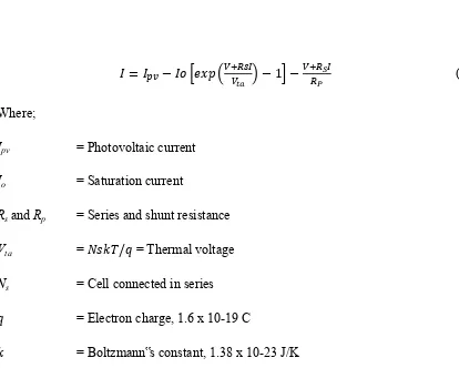
(2.1)
Where;
Ipv = Photovoltaic current
Io = Saturation current
Rs and Rp = Series and shunt resistance
Vta = = Thermal voltage
Ns = Cell connected in series
= Electron charge, 1.6 x 10⁻¹⁹ C
= Boltzmann‟s constant, 1.38 x 10⁻²³ J/K
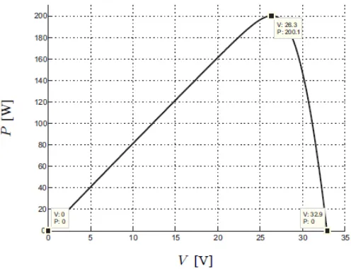
[image:21.595.88.502.77.409.2]In electrical principle, loads that connect in series would increase the output voltage while loads connect in parallel increase the output current. And same goes to PV system which constructed in array formation. This equation originates the I-V curve seen in Figure 2.4 [2], where three are highlighted which is short circuit (0,Isc), maximum power point (Vmp, Imp) and open-circuit (Voc, 0). For the power output, the P-V characteristic curve is shown in Figure 2.5 [2].
Figure 2.5: The P-V characteristic curve. Some advantages of PV system [1]:
Simple installation and long life (30 years) Low maintenance and light weight
Silent and clean
No moving parts and environmentally friendly
Some disadvantages are [1]:
Limited power and Inefficient on cloudy days
Drastic power reduction if any part of panel is shade
Renewable energy production is dependent on natural cycles, i.e. PV does not work at night
Initial cost of these systems is higher than comparably sized conventional generators
2.3 Wind turbine system
2.3.1 Definition
Wind turbines are used to generate electricity from the kinetic power of the wind. Historically they were more frequently used as a mechanical device to turn machinery [12]. In other words wind turbine is a device that changes kinetic energy from the wind source to generate mechanical energy. In windmills, wind energy is used to turn mechanical machinery to do physical work, such as crushing grain or pumping water. Wind power is used in large scale wind farms for national electrical grids as well as in small individual turbines for providing electricity to rural residences or grid isolated locations. Wind energy is plentiful, renewable, widely distributed, cleans, and reduces toxic atmospheric and greenhouse gas emissions if used to replace fossil-fuel derived electricity.
The wind energy is change through friction into diffuse heat throughout the Earth's surface and the atmosphere. The Earth is unevenly heated by the sun resulting in the poles receiving less energy from the sun than the equator does. Also the dry land heats up and cools down more quickly than the ocean do. The differential heating powers a global atmospheric convection system reaching from the Earth's surface to the stratosphere which acts as a virtual ceiling. There are some advantages and disadvantages of wind power on the surrounding environment, and the general reliability of wind turbines [13].
The advantages of wind energy:
1. Wind energy is very friendly to the surrounding environment because there are no fossil fuels are burnt to generate electricity from wind power.
2. WT takes up less space than the average power station.
3. WT is a suitable resource to generate electricity in remote locations, such as mountain and countryside communities.
The disadvantages of wind energy:
1. The main disadvantage of wind power system is down to the winds unreliability factor. If the wind speed is too low, then the WT would be considered as inefficient type of power source.
2. A WT can only support a specific population. WT aren't like power stations, where you can just burn a bit more fuel to generate more energy when you need it.
3. The noise pollution from commercial wind turbines is on a par with a small jet engine. 4. Vast protests and/or petitions usually confront any proposed wind farm site. People feel
the countryside should be left intact for everyone to enjoy its beauty.
2.3.2 System component
Designing a WT require numerous component of electrical and mechanical such as rotor blade, nacelle, transmission, generator and many more as shown in Figure 2.6. But this report would only discuss about the main component of WT which are rotor blade pitch angle, transmission and generator, since only these component are being used to develop the model.
![Figure 2.1: Basic physical structure of PV cell [2].](https://thumb-ap.123doks.com/thumbv2/123dok/561690.66297/18.595.169.447.533.626/figure-basic-physical-structure-pv-cell.webp)
![Figure 2.2: PV cell, PV module and PV array [10].](https://thumb-ap.123doks.com/thumbv2/123dok/561690.66297/19.595.238.400.517.720/figure-pv-cell-pv-module-and-pv-array.webp)
![Figure 2.3: Solar cell equivalent circuit model [2].](https://thumb-ap.123doks.com/thumbv2/123dok/561690.66297/20.595.166.444.369.494/figure-solar-cell-equivalent-circuit-model.webp)