SEMI ACTIVE SUSPENSION SYSTEM DESIGN FOR HEAVY DUTY TRUCK
MOHD SALMIZI BIN MAT NOR
This report is submitted in partial fulfillment of the requirement for the Bachelor of Mechanical Engineering (Automotive)
Faculty of Mechanical Engineering Universiti Teknikal Malaysia Melaka (UTeM)
ii
DECLARATION
“I hereby declare that the work in this report is my own except for summaries and quotations which have been duly acknowledged.”
iii
ACKNOWLEDGEMENT
First of all, I would like to be grateful to Almighty Allah for giving me a chance to complete my project. I wish to express my gratitude to my supervisor, Professor F. Golnaraghi, for his constant support, guidance and encouragement. The fundamental idea of this project is his and he was a valuable source of information about this project. I am very thankful that he supervised my work and provided my with the much needed assistance in understanding the project. Without his guidance and support, I may not be able to achieve the goals of this project.
iv
ABSTRACT
The study present a semi active control system in designing a controller for semi active. The mathematical model of a heavy duty truck were developed and the performance of semi active system were compared with passive system. This semi active control system was proposed to reduce the rolling and pitcing the truck body. It was proved by the result that semi active control system can improve the rolling and pitching of the truck.
v
ABSTRAK
Kajian menunjukkan sistem kawalan semi aktif dalam membina satu alat kawalan berdasarkan teori pembolehubah struktur. Satu model matematik tentang kenderaan berat di bina dan keputusan prestasi bagi semi aktif dan pasif dibandingkan. Tujuan alat kawalan semi aktif ini adalah untuk mengurangkan beberapa daya yang bertindak pada badan kenderaan berat. Ini dapat dibuktikan dengan keputusan kajian dimana alat kawalan semi aktif dapat meningkatkan daya pada badan kenderaan berat.
vi
CONTENT
CHAPTER SUBJECT PAGE
DECLARATION ii
ACKNOWLEDGEMENT iii
ABSTRACT iv
ABSTRAK v
CONTENT vi
LIST OF FIGURE viii
LIST OF TABLE x
LIST OF APPENDIX xi
CHAPTER 1 INTRODUCTION
1.0 Introduction to the semiactive suspension 1
1.1 Objective of the project 4
1.2 Scope of the project 5
1.3 Structure and layout of the report 5
1.4 Flow chart 6
CHAPTER 2 LITERATURE REVIEW
2.0 Introduction 8
2.1 History of Suapension System 9
2.2 Suspension System 10
2.2.1 The passive suspension System 10 2.2.2 The semiactive suspension system 11
2.2.3 The active suspension system 13
vii
CHAPTER 3 METHODOLOGY
3.1 Introduction 19
3.2 Flow chart 19
3.3 Equation of motion using MATLAB 22 3.3.1 Equation of motion quarter car model 22 3.3.2 Calculation for COG of the truck 23 3.3.3 Equation of motion half car roll plane model 25 3.3.4 Equation if motion half car pitch plane model 28 3.3.5 Equation of motion full car model(passive) 31 3.3.6 Equation of motion full car model(semiactive) 33 3.4 Control structure of semiactive suspension system 35
3.5 Controller design 37
3.5.1 PID theory 38
3.5.2 Manual tuning 38
3.5.3 Ziegler Nicols method 39
CHAPTER 4 RESULT AND DISCUSSION
4.1 Graph validation 41
4.2 Result 42
4.3 Simulation result 43
CHAPTER 5 CONCLUSION AND RECOMMENDATION
5.1 Suggestion for the future work 47
REFERENCE 49
BIBLIOGRAPHY 51
viii
LIST OF FIGURE
FIGURE TITLE PAGE
1.0 Vehicle suspension
(Source: www.wikipedia.org/wiki/Suspension) 1
1.1 Front suspension 2
1.2 Rear suspension 3
1.3 Semiactive suspension 3
1.4 Leaf spring 4
2.1 Passive suspension system
(Source: O durieux. et al. (2009)) 10 2.2 Semiactive suspension system
(Source: O durieux. et al. (2009)) 11
2.3 Skyhook damper
(Source: O durieux. et al. (2009)) 12 2.4 Active suspension system
(Source: O durieux. et al. (2009)) 13 2.5 Roll angle of a truck during passing a one side ramp
(Source: O. Vaculin et al. (1996)) 16 3.2 Quarter car model
(http://www.engin.umich.edu/class/ctms/simulink/examples/susp/
suspsim.htm) 22
3.3 Half car role plane model
(http://www.engin.umich.edu/class/ctms/simulink/.htm) 25 3.4 Heavy duty truck
(Source: “Heavy Duty Truck and Dimension Limit”,
page 23) 28
ix
(http://www.engin.umich.edu/group/ctm/examples/
susp/susp.html) 28
3.6 Blog diagram for the control structure 35
3.7 Blog diagram PID controller 37
3.8 Effect od increase parameter indepently 39
3.9 Ziegler-Nicols method 40
4.0 Passive and semiactive graph 41
4.1 Passive(yellow) and semiactive(purple) graph 41
4.2 Body vertical acceleration performance 44
4.3 Pitch acceleration performance 44
4.4 Pitch rate performance 45
4.5 Roll acceleration performance 46
x
LIST OF TABLE
TABLE TITLE PAGE
1 Parameter of heavy duty truck 23
2 Value of PID controller 42
xi
LIST OF APPENDIX
APPENDIX TITLE PAGE
A Gantt chart PSM 1 52
B Gantt chart PSM 11 53
C Quarter car simulink model 54
D Graph of quarter car simulink model 54
E Half car simulink model 55
CHAPTER II LITERATURE REVIEW
2.0 Introduction
The suspension of a car is actually part of the chassis, which comprises all of the important systems located beneath the car's body. Traditional vehicle suspension consists of combinations of springs and dampers. The roll trade-off of suspension systems has been a long standing challenge for vehicle dynamicists. Achieving better ride performance almost invariably leads to increased roll of the vehicle. To the car engineer this roll leads to
2.1 History of suspension system
By the early 19th century, most British horse carriages were equipped with springs’ wooden springs in the case of light one horse vehicles to avoid taxation, and steel springs in larger vehicles. These were made of low carbon steel and usually took the form of multiple layer leaf springs. The British steel springs were not well suited for use on America's rough roads of the time, and could even cause coaches to collapse if cornered too fast. In the 1820s, the Abbot Downing Company of Concord, New Hampshire developed a system whereby the bodies of stagecoaches were supported on leather straps called "thoroughbraces", which gave a swinging motion instead of the jolting up and down of a spring suspension. Automobiles were initially developed as self-propelled versions of horse drawn vehicles. However, horse drawn vehicles had been designed for relatively slow speeds and their suspension was not well suited to the higher speeds permitted by the internal combustion engine. In 1901 Mors of Germany first fitted an automobile with shock absorbers. With the advantage of having a dampened suspension system in his 'Mors Machine', Henri Fournier was able to win the prestigegous Paris-Berlin race on June 20th 1901. Fourniers superior time was 11 hrs 46 min 10 sec, while the best competitor was Léonce Girardot in a Panhard at the time 12 hrs 15 min 40 sec. In 1920, Leyland used torsion bars in a suspension system. In 1922, independent front suspension was pioneered on the Lancia Lambda and became more common in mass market cars from 1932.
2.2 Suspension system
The suspension system can be categorized into passive, semi-active and active
2.2.1 The passive suspension system
Figure 2.1: Passive suspension system
In early semi-active suspension system, the regulating of the damping force can be achieved by utilizing the controlled damper under dampers under closed loop control, and such is only capable of losing energy. Two types of dampers are used in the semi-active suspension namely the two state damper and the continuous variable dampers. The two state dampers switched rapidly between states under close-loop control . In order to damp the body motion, it is necessary to apply a force that is proportional the body velocity. Therefore, when the body velocity is in the same direction as the damper velocity, the damper is switched to the high state. When the body velocity is in the opposite direction to the damper velocity, it is switched to the low state as the damper is transmitting the input force rather than dissipating energy. The disadvantage of this system is that while it controls the body frequencies
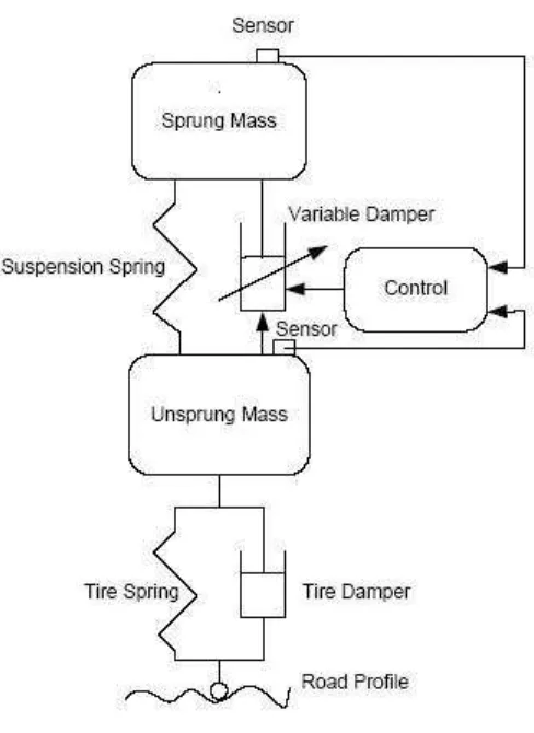
2.2.2 The semi active suspension system
Figure 2.2: Semi active suspension system
The continuous variable dampers have a characteristic that can be rapidly varied over a wide range. When the body velocity and damper velocity are in the same direction, the
mass and the unsprung mass need to be reduced. It is known that the skyhook damper alone cannot reduce both resonant peaks at the same time.
Figure 2.3: Skyhook damper
More recently, the possible applications of electroheological (ER) and