AUTOMATIC REFILLING MACHINE
MOHAMMAD AL-AMIN BIN SALLEH
This Report Is Submitted In Partial Fulfillment of Requirements for the Degree of Bachelor in Electrical Engineering (Power Electronic and Drive)
Faculty of Electrical Engineering Universiti Teknikal Malaysia Melaka
“I hereby declared that this report is a result of my own work except for the excerpts that have been cited clearly in the references.”
DEDICATION
Specially dedicated to my beloved family especially my mother
(Fatimah binti Hamat) and my late father (Allahyarham Salleh Bin Hussien); whose very concern, understanding, supporting and patient. Thanks for everything. To All My Friends, thanks for everything. This work and success will never be
ACKNOWLEDGEMENTS
Alhamdulillah, the highest thanks to God because with His Willingness, I possible to complete the final year project in time.
I would like to express my gratitude to my dedicated supervisor, En Ahmad Idil Bin Abdul Rahman for guiding this project with clarity and that priceless gift of getting things done by sharing his value able ideas as well as his knowledge.
I also like to thank to all UTEM lecturers and who had helped directly or indirectly in what so ever manner thus making this project a reality. Not forgotten are my best colleagues for their openhandedly and kindly guided, assisted, supported and encouraged me to make this project successful.
My heart felt thanks to my dearest family which always support and pray on me throughout this project. Their blessing gave me the high-spirit and strength to face any problem occurred and to overcome them rightly.
ABSTRACT
ABSTRAK
TABLE OF CONTENTS
CHAPTER TITLE PAGE
TITLE PAGE i
STUDENT DECLARATION ii
DEDICATION iii
ACKNOWLEDGEMENTS iv
ABSTRACT v
ABSTRAK vi
TABLE OF CONTENTS vii
LIST OF FIGURES xi
LIST OF TABLES xv
LIST OF SYMBOL xvi
LIST OF APPENDICES xvii
I INTRODUCTION 1.1 Background of Project 1 1.2 Problem Statement 1
1.3 Objective of Project 2
1.4 Scope of Project 3 1.5 Outline of Thesis 4 II LITERATURE REVIEW & THEORY 2.1 Introduction 5
2.2 Literature review 5 2.2.1 A Reliable Automatic Liquid 5
Nitrogen Filling System
2.3 Real-Time Implementation of a 7 Fuzzy Logic Controller for
2.2.3 Overflow filling systems 8 2.2.4 Piston filling systems 9
2.3 Hardware specification 10
2.3.1 Pneumatic Valve 10
2.3.1.1 Electro-pneumatic trainer 12 2.3.1.2 Single acting cylinder 13 2.3.1.3 Double acting cylinder 14
2.3.2 Microcontroller 15
2.3.2.1 I/O pin 17
2.3.3 DC motor 19
2.3.4 Proximity sensor 21
2.3.5 Capacitive Proximity sensor 22 2.3.6 Trough-beam sensor 23
2.3.7 Power Supply +5V 24
2.3.8 Liquid Crystal Display 25 2.3.9 Programmable Logic Controller 26
2.4 Software specification 29
2.4.1 Cx-programmer 29
2.4.2 Proteus 7.2 SP6 32
2.4.2.1 ISIS 7 Professional 32 2.4.2.2 ARES 7 Professional 33
III METHODOLOGY
3.1 Introduction 38
3.2 Hardware Implementation 39
3.2.1 Mechanical part 40
3.2.1.1 Design the model project 40
3.2.2 Electrical part 43
3.2.2.1 Display part 43
3.2.2.2 Input PLC 44
3.2.2.3 Output PLC 43
3.3 Software implementation 47
3.3.1 Cx-programmer 47
3.4 Flow chart 56
IV TESTING AND RESULT
4.1 Introduction 57
4.2 Experiment 57
4.2.1 Determine connection between 57 Transmitter and receiver infrared sensor.
4.2.1.1 Procedures 58
4.2.1.2 Result 59
4.2.1.3 Simulation 59
4.2.1.4 Experimental Result 60 Analysis
4.2.2 Determine +5V power supply 61 using 7895
4.2.2.1 Procedures 61
4.2.2.2 Result 61
4.2.2.3 Simulation 62
4.2.2.4 Experimental Result 63 Analysis
4.3 Testing project 63
4.3.1 DC Motor 63
4.3.2 Solenoid valve 64
4.3.3 Double acting cylinder 65
V CONCLUSION AND RECOMMANDATION
5.1 Introduction 67
5.2 Problem that occur 67
5.2.1 Using the suitable sensor 68
5.2.2 Research 68
5.2.3 Problem 69
5.2.4 Solution 69
5.3 Discussion 70
5.5 Conclusion 71 REFERENCES 72
APPENDICES
APPENDIX A – C -
LIST OF FIGURES
NO. TITLE PAGE
1.1 Scope of project 3
2.1 Drawing of automatic liquid nitrogen filling system 5 2.2 View of cross section of cap for supply Dewar 6 2.3 Fuzzy controller-based converter topology 7
2.4 Overflow filling system 8
2.5 Piston filling system 10
2.6 Single acting cylinder 12
2.7 Training for pneumatic and electro-pneumatic system 12
2.8 Design single acting cylinder 14
2.9 Symbol of single-acting cylinder 14
2.10 Design double acting cylinder 14
2.11 Schematic I/O pin of PIC16F877A 17
2.12 12V and 24V DC motor 20
2.13 Optical Wheel Rotation Sensor Circuit 21
2.14 Result of A/D conversion in two A/D registers 21
2.15 Capacitive Proximity Sensor 22
2.16 E3Z-TA 23
2.17 IC LM7805 24
2.18 Schematic circuit of +5V power supply 25
2.19 Liquid Crystal Display (LCD) 25
2.20 Programmable Logic Controller 27
2.21 Ladder diagram 27
2.22 Typical PLC Control system. 28
2.23 CX-programmer 29
2.24 Select CS1G/CJ1G 29
2.25 Program Diagram 30
2.26 The Toolbox 30
2.27 Example program 30
2.29 After transfer data. 31
2.30 Run the program 32
2.31 Proteus 7.2 32
2.32 Schematic diagram 33
2.33 Run the program 33
2.34 Schematic diagram 33
2.35 Click ARES 34
2.36 First Step 34
2.37 Second Step 35
2.38 Third Step 35
2.39 Four Step 36
2.40 Five Step 36
2.41 Six Step 37
2.42 Last Step 37
3.1 Block diagram of Automatic Refilling Machine 38
3.2 Design Automatic Refilling Machine 39
3.3 Picture of the project 39
3.4 Design of Automatic Refilling Machine. 40
3.5 Sketch of conveyer 41
3.6 Sketch DC motor couple with rod and bearing 41
3.7 Sketch of the conveyer from upper view 41
3.8 Sketch filling station 42
3.9 Part of filling station 42
3.10 Type of aluminum 42
3.11 Model of Automatic Refilling Machine 43
3.12 Circuit of display part 43
3.13 Input PLC 45
3.14 Output PLC 46
3.15 Circuit of relay connect to motor 46
3.16 Start condition 47
3.17 Sensor 1 detect condition 48
3.18 Bottle move checking station 48
3.19 Sensor 4 detect full condition 49
3.21 Bottle move feedback 49
3.22 Limit switch 1 detect 50
3.23 limit switch 2 detect 50
3.24(a) Flow chart for program PLC 51
3.24(b) Flow chart for program PLC 52
3.24(c) Flow chart for program PLC 53
3.25(a) Program of display part 54
3.25(b) Program of display part 54
3.26 Download files HEX for display part. 55
3.27 Display of program. 55
3.28 Flow Chart for this project. 56
4.1 Experiment with multimeter 57
4.2 Transmmitter infrared sensor 58
4.3 Receiver infrared sensor 58
4.4 Switch OFF 59
4.5 Switch ON 59
4.6 Simulation circuit (OFF) 60
4.7 Simulation circuit (ON) 60
4.8 Circuit of power supply +5V 61
4.9 When switch ON 61
4.10 Wave output for power supply 62
4.11 Simulation circuit. 62
4.12 Ladder diagram for DC Motor 63
4.13 Diagram for DC motor moving. 64
4.14 Ladder diagram for solenoid valve. 64
4.15 Diagram for the solenoid valve. 64
4.16 Ladder diagram when switch ON 65
4.17 Diagram for advancing valve. 65
4.18 Ladder diagram when switch OFF 65
4.19 Diagram for retracting valve 66
4.20 Testing the project. 66
4.21 Testing the project 66
5.1 Manual Fiber Amplifier (E3X-NA) 68
5.3 Price of E3X-NA 69
5.4 E3Z-TA 70
LIST OF TABLES
NO. TITLE PAGE
2.1 Type of Pneumatic valve 11
2.2 Advantages and disadvantages of various 19
types of DC motor
2.3 Specification of the motor 20
2.4 Standard model of photoelectric sensor 23
2.5 Operation of NPN sensor 23
2.6 Operation of PNP sensor 24
2.7 Mechanical specification 25
2.8 Pin assignment 26
3.1 List component for display circuit 44
3.2 Port input PLC 44
3.3 Port output PLC 45
3.4 List of component Automatic Refilling Machine 47
4.1 Result experiment 1 60
LIST OF SYMBOL
ARM - Automatic Refilling Machine PLC - Programmable Logic Controller LCD - Liquid Crystal Display
LED - Light Emitting Diode DC - Direct Current
RAM - Random Access Memory ROM - Read-Only Memory
PROM - Programmable Read-Only Memory
EPROM - Erasable Programmable Read-Only Memory I/O - Input/Output
IC - Integrated Circuit
LIST OF APPENDIX
NO. TITLE PAGE
A Project Planning 83
B Picture model of Automatic Refilling Machine 84
C Data Sheet PIC16F877 86
CHAPTER I
INTRODUCTION
1.1 Background of Project
Filling system is among the system in manufacturing sector for in Malaysia. The system can faster for the produce product in factory. In the industries, the filling used because the system to operated with automatic. All the operation in factory will be control through this system. But this system still need human for to look this operation system. This system must be to need human for to control system because the machine non-perfect.
Automatic refilling machine (ARM) wills a new innovation manufacturing industry especially sector filling. This system is commercial refilling system that involves Programmable Logic Controller (PLC) and microcontroller. The system operates automatically in three stations, which are refilling, checking, and feedback. PLC and microcontroller to using for control all process in this system.
The Liquid Crystal Display (LCD) and Light Emitting Diode (LED) will be used to display amount of product produce, throw and system security.
1.2 Problem Statement
In refilling sector, the process must done fast to ensure the efficient of the machine. It is a fact that when using refilling process manually needs many workers. This is because every section needs workers to make sure all the product that developed is working smoothly and to prevent any problems that may occur during the refilling process.
As a solution Automatic Refilling Machine will be made. It will solve the problems that small industries face today. With this system that operates automatically, every process can be smooth and the process of refilling can reduce workers cost and operation time. The system operates by the program that designed to do the operation
1.3 Objective of Project
There are four objective of this project:
To design a system that operates automatically using PLC.
To use a Microcontroller PIC16F877A to display the information about the process of refilling machine.
To integrate the PLC and PIC system to operated the complete Automatic Refilling Machine.
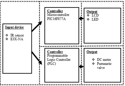
1.4 Scope Of Project
Figure 1.1: Scope of project
In system this, there were 3 part to control all Automatic Refilling Machine's whole operation. Among this parts are input device, controller and output device. This part important to system because can be control all operation with perfect. For this input device part, IR sensor and E3X-NA used to give signal for controller to operate this system. PIC16F877A and PLC used as controller for this system when accepted signal from input device. Microcontroller PIC16F877A used to control output through signal forwarded by sensor. The signal stated will be translated in language micro C to be sent to Liquid Crystal Display (LCD) for the all display process. For the PLC, signal from sensor will be translated in language from cx-programmer and sent to DC motor and pneumatic valve.
Input device
IR sensor E3X-NA Controller Microcontroller PIC16F877A Controller Programmable Logic Controller (PLC) Output LCD LED Output
DC motor Pneumatic
1.5 Outline Of Thesis
In this project, I would like to design the machine filling. In this report, I will discuss it in detail in five sections. There are introduction, literature review, methodology, results and discussions, and conclusion
In chapter one (introduction), I discussed about the major characteristics to be Automatic Refilling Machine. The problem statement, project objectives, scope and thesis outline are also included in this chapter.
In chapter two (literature review), the comparison is made by discussing the operation for automatic system and application of filling system. Later, each part of the Automatic Refilling Machine is discussed in detail.
In chapter three (methodology), I discussed about the techniques and consideration that I applied during I carried out my PSM1 and PSM2. Infrared sensor is an important part for the Automatic Refilling Machine to operate with successfully. In simulation part, Proteus software is used to simulate the design circuit before I proceed to the hardware part.
In chapter four (results and discussions), the results are obtained using the methodology discussed in previous chapter. Then, Proteus 7.2 SP6 simulation is done to the design circuit to ensure it functions probably. This is determined by looking at the data obtained during simulation. Finally, I proceed to the hardware part. Here all the obtained results are gathered. Finally, analysis is done according to the results.
CHAPTER II
LITERATURE REVIEW & THEORY
2.1 Introduction
This chapter includes the study of different types of a reliable automatic liquid nitrogen filling system, real-time implementation of a fuzzy logic controller for switch-mode power-stage dc–dc converters and pneumatic valve. It also brief discuss about microcontroller, DC motor, proximity sensor and filling system.
2.2 Literature review
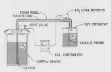
[image:22.595.230.409.506.622.2]2.2.1 A Reliable Automatic Liquid Nitrogen Filling System
Figure 2.1: Drawing of automatic liquid nitrogen filling system
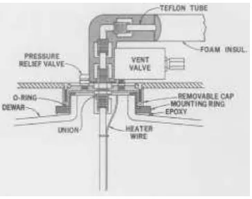
computer, the fill controller activates the fill cycle. This closes the normally open vent valve on the supply Dewar and turns on the internal heater. The pressure build-up forces the liquid nitrogen through the foam insulated Teflon tube to the detector cryostat. When the liquid nitrogen in the detector cryostat reaches the preset stop fill level, the controller turns off the heater and opens the vent valve [1]. Figure 2.2 show the view of cross section of cap for supply Dewar.
Figure 2.2: View of cross section of cap for supply Dewar
The advantages of this system are:
a) The liquid nitrogen level monitor provides a continuous output of the level b) The probe does not require heating as resistor or thermister types do. This
conserves liquid nitrogen in the cryostat.
c) The fill and stop levels are set electrically in the controller and do not require mechanical.
d) No valve is used in the liquid nitrogen line (The plague of most automatic liquid nitrogen filling systems).
e) The fill tube made of Teflon is insulated with foam insulation and is more reliable than other plastic fill tubes. The fact that the thermal capacity is much lower than metal fill tubes means that much less liquid nitrogen is used to cool it down [1].
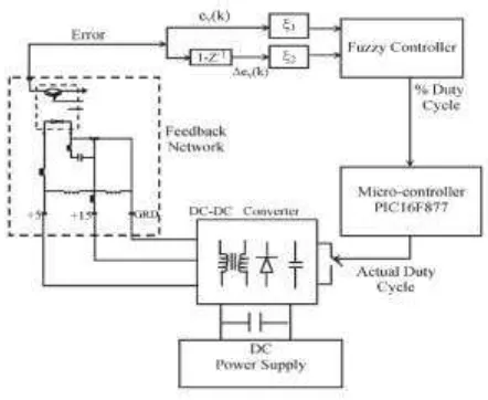
Figure 2.3: Fuzzy controller-based converter topology
Figure 2.3 show the fuzzy controller-based converter topology for this system. The structure built up here is a two-input single-output controller. The inputs are the variable voltage error e(k) and the change in voltage error Δe(k). Consequently, the input to the dc–dc converter would be the duty cycle, which is actually the output of the fuzzy controller. Fuzzification translates a numeric value for the error e(k) or change in error Δe(k) into a linguistic value such as big or small with a membership grade. Defuzzification takes the fuzzy output of the rules and generates a numeric value used as the control input to the dc–dc converter. The controller qualitatively captures the dynamics of the dc–dc converter and executes this qualitative idea in a real-time situation [2]. The dc–dc converter is equipped with a feedback network that provides the error value at the output [3].
This output voltage is then compared internally to the reference of the precision voltage reference, and any error difference detected is amplified and fed back. The controller provides a percentage duty-cycle signal for a peripheral interface microcontroller PIC16F877, which generates the converter actual duty cycle [3].