DESIGN OF DAYLIGHT INTENSITY DETECOR FOR POWER SYSTEM
MOHD AZRUL BIN ABDUL TALIB
A report submitted in partial fulfillment of the requirement for the degree of Bachelor in Electrical Engineering (Industrial Power)
Faculty of Electrical Engineering
UNIVERSITI TEKNIKAL MALAYSIA MELAKA
―I hereby declare that I have read through this project entitle ―Design of Daylight Intensity Detector for Power System‖ and found that it has comply the partial fulfillment for
awarding the degree of Bachelor of Electrical Engineering (Industrial Power) ‖
Signature : ……….
Supervisor Name : En. Kyairul Azmi Bin Baharin
I declare that this report entitle ―Design of Daylight Intensity Detector for Power System‖ is the result of my own research except as cited in the references. The report has not been accepted for any degree and is not concurrently submitted in candidature of any degree.
Signature :
Name : Mohd Azrul Bin Abdul Talib
To my beloved mother and father
ACKNOWLEDGEMENT
Bissmillahirahmanirahim... In the name of Allah S.W.T, the most gracious and merciful, praise to Allah the lord of universe and may blessing and peace of Allah be upon his messenger Muhammad S.A.W. Thanksgiving to Allah because He has give me the opportunity to complete my final year project and final year report. Without His blessing, I can‘t complete this task in the time given.
Firstly, I would like to appear my grateful to Mr. Kyairul Azmi Bin Baharin, who is my final year project‘s supervisor. He shows the best responsibility to guide me, give a valuable ideal, understanding, patient and show me the correct way to follow up in doing final year report. Actually, I never forget his effort, responsibility and contribution as my supervisor as well as my good lecturer.
I also would like to thank my best friend, Ghafar Bin Jenal and others friend who helps me especially in Visual Basic program, guide me the basic of progress bar, timer, program button, blinking light and interfacing port setting. He shows a good effort and contribution to help me in Visual Basic coding. Besides that, he also gives a valuable ideal in solving problem to my final year project.
Secondly, a special thanks to the reviewers of this report who contributed significantly to this final year project and to all of my friends, who offered valuable suggestion to finished this report.
ABSTRACT
ABSTRAK
AC
TABLE OF CONTENTS
CHAPTER TITLE PAGE
ACKNOWLEGDEMENT v.
ABSTRACT vi.
ABSTRAK vii.
TABLE OF CONTENTS viii.
LIST OF TABLES xi.
LIST OF FIGURES xii.
LIST OF APPENDICES xiv.
1 INTRODUCTION 1
1.1 Background 1
1.2 Problem statement 2
1.3 Project Objective 2
1.4 Project Scope 3
2 LITERATURE REVIEW 4
2.1 Introduction 4
2.2 Lighting Control System 5
2.3 Light Sensor 6
2.3.1 Introduction 6 2.3.2 Light Independent Resistor (LDR) 7
2.3.3 Photodiode 8
2.4 Light Meter 11 2.4.1 Data Logging Light Meter 12 2.5 Previous Technology on Automatic Lighting System 13
2.6 Parallel Port 14
2.7 Optocoupler 16
2.8 Relay 17
2.9 Diode 18
2.10 Transistor 19
2.11 Microsoft Visual Basic V6.0 20 2.12 Lighting Requirement for Workspace 20
3 PROJECT METHODOLOGY 23
3.1 Project Background 23
3.2 Project Flow Chart 25
3.3 Explanation Of Project Flow Chart 27 3.4 Interface Circuit Design 29 3.5 Simulation Interface Circuit 31 3.6 Interface Circuit Operation 32 3.7 Interface Circuit Elements and Component 34
3.8 Project Planning 37
4 RESULTS AND DISCUSSION 39
4.1 Daylight Intensity Analysis 39
4.2 Daylight Intensity Analysis in FKE, UTeM 39
4.3 Daylight Intensity Analysis for Study Room 40
4.4 Interface Circuit Simulation Result and Analysis 44
4.5 Interface Circuit Simulation Analysis 45
4.5.1 Parallel Port Connector 46
4.6 Software Program Development and Analysis 48
4.6.1 Splash Screen window 49
4.6.2 Welcome Window 50
4.6.3 Introduction Window 51
4.6.4 MyADID Window 52
4.6.5 MyADID Analysis 53
4.7 Computer Programming 55
4.8 Hardware Result and Analysis 56
4.9 Chronology of MyADID Software Program Usage 58
5 CONCLUSION AND RECOMMENDATION 60
5.1 Conclusion 60
5.2 Recommendation 63
REFERENCES 65
LIST OF TABLES
TABLE TITLE PAGE
2.1 Parallel Port Signal Lines 15
2.2 Reasonable Lighting Levels 21
2.3 Lighting Requirement for Workspace 22
LIST OF FIGURES
FIGURES TITLE PAGE
2.1 Light dependent Resistance (LDR) 7
2.2 Symbol of Light Dependent Resistance (LDR) 7
2.3 Photodiode 8
2.4 Symbol of Photodiode 8
2.5 Phototransistor 10
2.6 Symbol of Phototransistor 10
2.7 Light Meter 11
2.8 Data Logging Light Meter 12
2.9 Automatic Lighting System 13
2.10 Parallel Port 14
2.11 NPN Transistor 19
2.12 PNP transistor 19
3.1 Overall project operation 23
3.2 Project flow chart 25
3.2 Project flow chart 26
3.3 Interface circuit design flow chart 29
3.4 Simulation flow chart 31
3.5 Interface schematic diagram 32
3.6 Parallel port pin with casing 34
3.7 Parallel port connection cable 34
3.8 Ribbon cable 34
3.9 Optocoupler 35
3.10 470Ω and 4.7Ω resistor 35
3.11 6V 100Ω Tripping relay 35
3.12 Veroboard 36
3.13 BC 148 transistor 36
3.15 Project planning part II 38
4.1 Dimension and allocation setup 40
4.2 Graph of daylight intensity level versus time (hour) 18 March 2009 42 4.3 Graph of daylight intensity level versus time (hour) 22 April 2009 43
4.4 Simulation circuit design 45
4.5 Parallel port connector simulation result 46 4.6 Simulation result without operation of tripping relay 47 4.7 Simulation result with changes of tripping relay 47
4.8 Splash screen window 49
4.9 Welcome window 50
4.10 Introduction window 51
4.11 MyADID window 52
4.12 Setup hardware before operation 56
4.13 Setup hardware during operation 57
4.14 MyADID software program 58
LIST OF APPENDICES
A P P E N D I X
TITLE PAGE
A Interface switching circuit for electrical appliance 67
B Basic coding in controlling electrical appliance 68
C MyADID programming coding 70
D Automatic Daylight Intensity Apparatus setup 72
CHAPTER 1
INTRODUCTION
1.1Background
Automatic daylight intensity detector is a project designed to control the lighting system automatically. The lighting system is automatically controlled by a computer based on the changes of sunlight intensity detected from data logger light meter. The automatic system also designed to introduce the new technology of automatic lighting control system.
Today, there are many improvements on lighting system to provide efficient lifestyles. The latest technology on lighting system is automatic ON/OFF lighting system which controlled by a relay. This system used to operate the lighting system at night and terminate the operation on the morning. Therefore, this automatic switching system still have some problem which is the lighting system does not operates properly on the time setting due to setting error and relay damaged.
operate the lighting system based on the different levels of daylight intensity detected by data logging light meter and setting value of daylight intensity requirement on the specified room or workspace. The weather change abruptly. It can be sunny for one minute and cloudy on the next. Daylight intensity detector function as a device that can determine when the natural lighting (i.e. daylight) in a building is too low (when it is rainy or cloudy) and turn ON the lights powered by the grid supply automatically. Otherwise, supply turned OFF when the natural lighting back to normal condition. This system also can be used for laboratory room, school, office, class room and etc.
Implication of using this automatic daylight intensity detector, lifestyle becomes more comfortable and efficient. Hence, using this daylight intensity detector system, it may help user to decrease their energy consumption.
1.2 Problem Statement
The weather changes abruptly, it can be sunny in one minute and cloudy the next. When the weather changing from bright to cloudy, users might have a problem to continue their office work or students cannot continue their study because of the lowest level of daylight intensity is at that time and they need to switch the light ON to help them in continuing their work. This situation will make user feel distracted while doing their work everyday. Therefore, ―Automatic Daylight Intensity Detector‖ was designed to fix this problem and make user life become more easy and comfortable. The automatic daylight intensity detector is a device that used to determine the changes of natural lighting (i.e. daylight) in a building and switch ON lighting system when environment brightness is low while switch OFF the system when natural lighting is back to normal condition.
1.3 Project Objective
project existence. The aim of this project is to design an automatic daylight intensity detector for electrical power system (lighting system). The main objectives were:
a) To design an automatic daylight intensity detector able to control the lighting system based on the daylight intensity detected by data logging light meter.
b) To conduct an analysis about sunlight intensity in FKE, UTeM.
c) To setup a proper interfacing circuitry between the hardware and software devices for automatic operation
d) To develop a Graphical User Interface (GUI) for this system using Visual Basic V6.0
e) To utilize the concept of parallel port in designing the software program to control circuit.
f) To verify whether the automatic daylight intensity detector can help to reduce daily energy consumption.
1.4 Project Scope
The scope of this project is to design automatic daylight intensity detector for power system. This project can be used for laboratory room and other workspace in FKE buildings, residential building, and etc. for example, this automatic daylight intensity detector can be used in lecture hall of FKE building to activate the lighting system automatically during the cloudy or rainy day.
CHAPTER 2
LITERATURE REVIEW
2.1 Introduction
Literature review is a body of text to review the critical points of current
knowledge on a particular topic.
Most often associated with science-oriented literature. The literature review usually precedes a research proposal, methodology and results section. Its ultimate goal is to bring the reader up to date with current literature on a topic and forms the basis for another goal, such as future research that may be needed in the area.
A good literature review is characterized by a logical flow of ideas, current and relevant references with consistent, appropriate referencing style, proper use of
terminology, and an unbiased and comprehensive view of the previous research on the topic.
2.2 Lighting Control System
Lighting control system consists of a device, typically an embedded processor or industrial computer, the controls electric lights for a building or residence. Lighting control systems usually include one or more keypads or touch panelinterfaces. These interfaces allow users the ability to toggle power to lights and fans, dim lights, and program lighting levels. [1]
A major advantage of a lighting control system over conventional lighting is the ability to control any device from any interface. For example, a master touch panel might allow the user the ability to control all lights in a building, not just a single room. In fact, any light might be controlled from any location.
In addition, lighting control systems provide the ability to automatically power a device based on programming events such as:
Chronological time (time of day) Astronomical time (sunrise/sunset) Room occupancy
Events
Alarm conditions
Program logic (any combination of events)
Chronological time is a time of day or offset from a time. Astronomical times includes sunrise, sunset, a day, or specific days in a month or year. Room occupancy might be determined with motion detectors or RFID tags. Events might include holidays or birthdays. Alarm conditions might include a door opening or motion detected in a protected area. Program logic can tie all of the above elements together using constructs such as if-then-else statements and logical operators.
system and are often used to control house lights, and sometimes work lights,
rehearsal lighting, and lobby lighting. Control stations are placed in several locations around the building and range in complexity from a single button that brings up a preset look to in-wall LCD touch screens. Much of the technology is related to residential and commercial lighting control systems.
The benefit of architectural lighting control systems in the theater is the ability for theater workers to turn work lights and houselights on and off without having to use a lighting control console. On the other hand, the light designer can control these same lights with light cues from the lighting control console so that, for instance, the transition from houselights being up before a show starts and the first light cue of the show is controlled by one system.
2.3 Light Sensor
2.3.1 Introduction
Light Sensors are used to measure the radiant energy that exists in a very narrow range of frequencies basically called "light", and which ranges in frequency from "Infrared" to "Visible" up to "Ultraviolet" light. Light sensors are passive devices that convert this "light energy" whether visible or in the infrared parts of the spectrum into an electrical signal output. Light sensors are more commonly known as "Photoelectric Devices" or "Photo sensors" which can be grouped into two main categories, those which generate electricity when illuminated, such as Photovoltaic or Photo missives etc, and those which change their electrical properties such as Photo resistors or Photoconductors. [11]
Figure 2.1: Light dependent resistor (LDR)
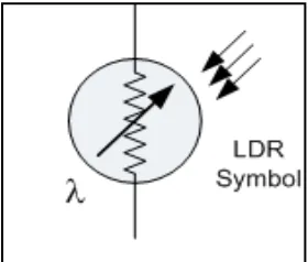
Figure 2.2: Symbol of light dependent resistor (LDR)
Light dependent resistor is one of photo conductive cell which is the light sensors change their physical properties when subjected to light energy. The most common type of photoconductive device is the Photo resistor which changes its electrical resistance in response to changes in the light intensity. Photo resistors are Semiconductor devices that use light energy to control the flow of electrons, and hence the current flowing through them. The commonly used Photoconductive Cell is called the Light Dependant Resistor or LDR. [11]
[image:22.595.232.372.292.411.2](Cds), as its spectral response curve closely matches that of the human eye and can even be controlled using a simple torch as a light source. Typically it has a peak sensitivity wavelength (λp) of about 560nm to 600nm in the visible spectral range.
The resistance of LDR may typically have the following resistances
Daylight = 5000Ω Dark = 20000000 Ω
2.3.3 Photodiode
Figure 2.3: Photodiode
Figure 2.4: Symbol of photodiode
can detect both visible light and infrared light levels. These classes of photoelectric light sensors include the Photodiode and the Phototransistor. [11]
The construction of the Photodiode light sensor is similar to that of a conventional PN-junction diode except that the diodes outer casing is transparent so that light can fall upon the junction. LED's can also be used as photodiodes as they can both emit and detect light. All PN-junctions are light sensitive and can be used in a photoconductive (PC) mode with the PN-junction of the photodiode always "Reverse Biased" so that only the diodes leakage or dark current can flow. This reverse bias condition causes an increase of the depletion region which is the sensitive part of the junction.
The photodiodes dark current (0 lux) is about 10uA for geranium and 1uA for silicon type diodes. When light fall upon the junction more hole/electron pairs are formed and the leakage current increases. The leakage current increases as the illumination of the junction increases. Diode current is directly proportional to light intensity. One main advantage of photodiodes when used as light sensors is their fast response to changes in the light levels, but one disadvantage of this type of photo device is the relatively small current flow even when fully lit.
Photodiodes are very versatile light sensors and are commonly used in cameras, light meters, CD and DVD-ROM drives, TV remote controls, scanners, fax machines and copiers etc, and when integrated into operational amplifier circuits as infrared spectrum detectors for fiber optic communications, burglar alarm motion detection circuits and numerous imaging, laser scanning and positioning systems etc.