UNIVERSITI TEKNIKAL MALAYSIA MELAKA
AUTOMATIC SYSTEM FOR CAR HEADLAMP
This report submitted in accordance with requirement of the Universiti Teknikal Malaysia Melaka (UTeM) for the Bachelor’s Degree in Electronic Engineering
Technology (Industrial Electronic) (Hons.)
by
AZWAN BIN MUHAMAD
B071110396 900405-01-5969
UNIVERSITI TEKNIKAL MALAYSIA MELAKA
BORANG PENGESAHAN STATUS LAPORAN PROJEK SARJANA MUDA
TAJUK: Automatic System for Car Headlamp
SESI PENGAJIAN: 2014/15 Semester 2
Saya AZWAN BIN MUHAMAD
mengaku membenarkan Laporan PSM ini disimpan di Perpustakaan Universiti Teknikal Malaysia Melaka (UTeM) dengan syarat-syarat kegunaan seperti berikut:
1. Laporan PSM adalah hak milik Universiti Teknikal Malaysia Melaka dan penulis. 2. Perpustakaan Universiti Teknikal Malaysia Melaka dibenarkan membuat salinan
untuk tujuan pengajian sahaja dengan izin penulis.
3. Perpustakaan dibenarkan membuat salinan laporan PSM ini sebagai bahan pertukaran antara institusi pengajian tinggi. atau kepentingan Malaysia sebagaimana yang termaktub dalam AKTA RAHSIA RASMI 1972)
(Mengandungi maklumat TERHAD yang telah ditentukan oleh organisasi/badan di mana penyelidikan dijalankan)
Alamat Tetap:
NO. 1311 Jalan Bakawali 1
Blok 11, Felda Maokil 1, 85300
Segamat Johor,
Tarikh: 10/12/2014
Disahkan oleh:
Cop Rasmi:
Tarikh: _______________________
iv
DECLARATION
I hereby, declared this report entitled “Automatic System for Car Headlamp” is the results of my own research except as cited in references.
Signature : ………
Author’s Name : AZWAN BIN MUHAMAD
v
APPROVAL
This report is submitted to the Faculty of Engineering Technology of UTeM as a partial fulfillment of the requirements for the degree of Bachelor of Engineering Technology (Industrial Electronic) (Hons.). The member of the supervisory is as follow:
……….
vi
ABSTRAK
vii
ABSTRACT
viii
DEDICATION
This final year report is dedicated to my beloved parents who have supported me all the way since the beginning of my studies.
Also, this final year report is dedicated to my special friend that always with me and close friends who have been a great source of motivation and inspiration.
ix
ACKNOWLEDGEMENT
Bissmillahirrahmanirrahim,
Alhamdulillah. Thanks to Allah SWT, who with His willing had given me the opportunity to complete this Final Year Project which is Automatic System for Car Headlamp.
Firstly, I would like to express my deepest thanks to, En. Tg Mohd Faisal Bin Tengku Wook, as my supervisor who had guided and advised me a lot during this two semesters. I also want to thanks all the lecturers and staffs of Faculty of Engineering Technology UTeM for their cooperation when I needed to complete the final year project that had given valuable information, suggestions and guidance in the compilation and preparation to this final year project report.
x
xi
2.6.1 Low Frequency Lamp Operation 17
2.6.2 Lamp Performance Point to Be Considered 18
2.6.3 High Frequency 18
CHAPTER 3: METHODOLOGY 19
3.1 Flow Chart of Process 19
3.2 Project Built 21
3.3 Research 22
3.4 Hardware and Software Analysis 22
3.5 Circuit Design 23
3.5.1 Transmitting Device 24
3.5.2 Receiving Device 24
3.5.3 The Expected Result 25
CHAPTER 4: RESULT & DISCUSSION 26
4.1 Circuit Analysis 26
4.1.1 Automatic ON When Dark Circuit 34
4.1.2 Automatic OFF When There Is Incoming Car or Object 35
4.2 Circuit Implementation 36
CHAPTER 5: CONCLUSION & FUTURE WORK 39
5.1 Project Conclusion 39
5.2 Recommendation and Future Development 40
xii
LIST OF TABLES
2.1 The Approximate Analog Voltage Based On The Sensor
Light/Resistance W/A 5v Supply And 10kω Pull Down Resistor.
7
2.2 The Approximate Analog Voltage Based On The Sensor Light/Resistance
8
2.3 Brightness Description 9
2.4 The Operating Characteristics of HID Lamps 16
xiii
LIST OF FIGURES
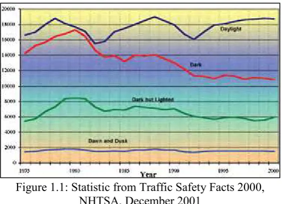
1.1 Statistic from Traffic Safety Facts 2000, NHTSA, December 2001
3
2.1 Photocells 5
2.2 Typical Construction of a Plastic Coated Photocell 6
2.3 Resistance VS Illumination 6
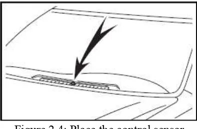
2.4 Place The Control Sensor 10
2.5 Spectral Response 13
2.6 Bi-Pin, Screw and Double Ended Base Types 15
2.7 Elliptical and Tubular HID Lamps 16
2.8 Acoustic Node Map For A 400 4att Ceramic Metal Halide Hid Lamp
18
3.1 Flow Chart Of Process To Build The Project 20
3.2 Flow chart of automatic ON car headlamp 21
3.3 Flow Chart Of Automatic High Beam And Low Beam 21 3.4 Circuit Design For Automatic High Beam And Low Beam 23
3.5 Circuit Design For Transmitting Device 24
3.6 Circuit Design Of The Receiving Device 25
4.1 Power Dissipation And Ambient Temperature 27
4.2 Resistance As A Function Illumination 27
4.3 How The Ir Sensor Operate 29
4.4 Scheme Of The Dimming Vehicle High Beam Headlamps Problem
29
4.5 The Relation Between The Incoming Light Luminance And The Distance
31
xiv 4.7 Relation Between The LDR Resistance And The Incoming Light
Luminance
33
4.8 Relation Between Incoming Light Luminance And The Ldr Resistance With The Distance
33
4.9 Circuit Automatic ON When Dark 34
4.10 Indicator ON When Dark 34
4.11 Circuit Automatic Off When There Is Light And Object 35
4.12 Position Of Sensor On The Car 36
4.13 Car Headlamps Is On When LDR 1 Detect The Low Level Of Light
37
4.14 High Beam Will OFF When LDR 2 Detect A Light 37
4.15 High Beam Will OFF When IR Sensor Detect An Object In Front Of The Car
38
4.16 High Beam of Car Headlamp Will ON When Sensor LDR 2 and IR Sensor Did Not Detect Incoming Light And Object.
38
xv
LIST OF ABBREVIATIONS, SYMBOLS AND
NOMENCLATURE
FARS - Fatality Analysis Reporting System
NHTSA - National Highway Traffic Safety Administration LDR - Light Dependant Resistor
CdS - Cadmium Selenide (inorganic compound)
R - Resistor
HID - High Intensity Discharge L.F.S.W - Low Frequency Square Wave
A.R - Acoustic Resonance
EM - Energy Multiplier
CWA - Constant Wattage Autotransformer
IR - Infra Red
1 This chapter will discuss the overview process that involved for this project which is project background and specific objectives of the project, problem statements, scope of work and project significance. The end of this chapter the thesis outline will be listed.
1.1 Background of the Study
Driving the highway with our high-beam headlights can really increase our visibility, but it also can be a blinding hazard for other drivers. This automatic system for car head lamp can automatically switch ON the head lamp when the light or the ambient light is decrease. This headlight switch to provide automatic switching between high and low beam headlights when there is oncoming traffic. It does this by sensing the lights of that traffic. In this way, we can drive safely with our high-beams on without blinding other drivers.
1.2 Problem Statement
Crash statistics can shed some light on the impact that time of day has on driver risk. An analysis of the Fatality Analysis Reporting System (FARS) data such as in Figure 1.1 for 2000 reveals that, 49 percent of all fatal crashes occur at night, 81 percent of fatal crashes occur on dry pavement, both day and night, 40 percent of all fatal crashes involve alcohol as a factor, with more than 60 percent of those occurring at night, and problems with driver vision, vehicle hardware, or
2 environmental conditions are cited as "related factors" in 15 percent of all fatal crashes. Since more than half of all fatal crashes involve only a single vehicle, the final statistic may greatly underestimate the impact of vision and visibility on driving safety.
Law Offices of Michael Pines APC, write that, 60 percent less traffic on the roads, more than 40 percent of all fatal car accidents occur at night. Then, the number of persons seriously injured increases by 50% and the number of death by 36% compared with accidents during the day. Driving either just before sunrise (dawn) or immediately after sunset (dusk) are also very dangerous time periods on the roadways, and many car accidents occur during these times.
However, the vision even of a person with normal eyes reduced at night. The associated risk factors include delayed adjustment to changes between light and dark, impaired color vision and the slow transition from day to night, through habituation effect can lure the motorist into a false of security.
Headlamps are typically controlled to alternately generate low beams and high beams. Low beams provide less illumination and are used at night to illuminate the forward path when other vehicles are present. High beams provide significantly more light and are used to illuminate the vehicle’s forward path when other vehicles are not present.
Daylight running lights have also begun to experience widespread
acceptance. High beam are used for illuminating a road doesn’t have very much
traffic on it. By that way the driver can see further ahead for any road obstructions.
High beam is also used when a driver is one an unfamiliar road and if there isn’t
3
1.3 Objectives
The objective of the project includes:
The objective of this project is to solve the problem that usually faced by almost all driver when they drive at night.
To study the operation and application of light sensor. To analyze the performance car headlamp.
1.4 Project Scope
The concept of the system basically can be divided into two parts which is the light detection and the high beam off/on control circuit. In order to design a simple low cost control system, a simple approach is needed to detect the light of the incoming traffic or the ambient lights in the road. A light dependent resistor (LDR) is used (some literature refers to it as photo resistor) as a light sensor. The resistance value of the LDR is changing according to the impinging light on it. Typical LDR has a linear relation with the incident light such that if the light density is increased the resistance of the LDR is decreased. Other electronic components such as a transistor, operational amplifier (used as comparator), relay, diodes and resistor are used to build the electronic control circuit.
4 Chapter 2 describes on the analysis and review about component and its importance in this project. This chapter discuss about the contents of the photocell sensor, definition of lux, headlight control sensor, visible spectrum and main lighting switch.
2.1 Automatic Lighting System
This automatic lighting system will immediately switch on the headlight as soon as light becomes poor and vice versa. Where and when we need this system, firstly, we will need this system when we entering the tunnel. Some tunnel have a streetlight, some does not have streetlight. After that, we need this system when we enter the underground car park. Then when the nightfall or when the weather become dark.
2.1.1 How Does It Works
An optical sensor, fitted on the windscreen, permanently detects light levels. When the light drops to less than 1,000 lux, the electronic control unit activates the
vehicle’s lighting automatically. When the light returns to 3,000 lux, the lights are automatically switched off in less than 20 seconds. The system can easily be switched off to return to manual mode using the on/off switch on the sensor.
5
2.2 Photocells
2.2.1 Description
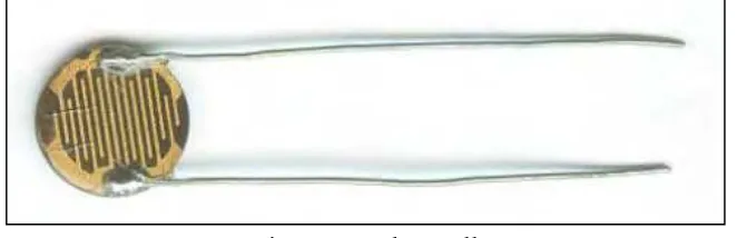
Photocells are sensors that allow you to detect light. They are small, inexpensive, low-power, easy to use and don't wear out. For that reason they often appear in toys, gadgets and appliances. They are often referred to as CdS cells (they are made of Cadmium-Sulfide), light dependent resistors (LDR), and photo resistors.
Photocells are basically a resistor that changes its resistive value (in ohms Ω)
depending on how much light is shining onto the squiggly face. They are very low cost, easy to get in many sizes and specifications, but are very inaccurate. Each photocell sensor will act a little differently than the other, even if they are from the same batch. The variations can be really large, 50% or higher! For this reason, they shouldn't be used to try to determine precise light levels in lux or millicandela. Instead, you can expect to only be able to determine basic light changes.
Figure 2.1: Photocells
6 Figure 2.2: Typical Construction of a Plastic Coated Photocell
2.2.2 Measuring Light
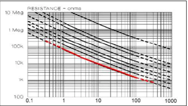
A photocell's resistance changes as the face is exposed to more light. When
its dark, the sensor looks like a large resistor up to 10MΩ, as the light level increases,
the resistance goes down. This graph indicates approximately the resistance of the sensor at different light levels.
7
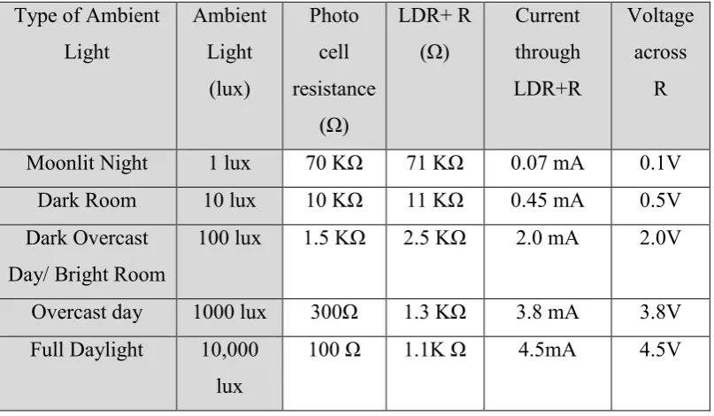
2.2.3 Using a Photocell
The way this works is that as the resistance of the photocell decreases, the total resistance of the photocell and the pull down resistor decreases from over
600KΩ to 10KΩ. That means that the current flowing through both resistors increases which in turn causes the voltage across the fixed 10KΩ resistor to increase.
2.2.4 Basic Statistic
Nearly all photocells will have slightly different specifications, although they all pretty much work the same. This range of photocells includes three different size designs with different spectral sensitivity. The smallest in physical size is our A 9950 range with spectral sensitivity at max. 530 nm.
Size: Round, 5mm (0.2") diameter. (Other photocells can get up to 11mm/0.4" diameter!)
Resistance range: 200K ohm (dark) to 10K ohm (10 lux brightness)
Sensitivity range: CdS cells respond to light between 400nm (violet) and 600nm (orange) wavelengths, peaking at about 520nm (green).
Power supply: pretty much anything up to 100V, uses less than 1mA of current on average (depends on power supply voltage)
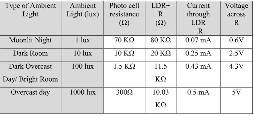
Table 2.1: The approximate analog voltage based on the sensor light/resistance w/a
5V supply and 10KΩ pull down resistor.
8 down, it will quickly saturate. That means that it will hit the 'ceiling' of 5V and not be able to differentiate between bright and really bright. In that case, we should
replace the 10KΩ pull down with a 1KΩ pull down. In this case, it will not be able to detect dark level differences as well but it will be able to detect bright light differences better.
9
2.3 Definition of Lux
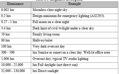
Most datasheets use to indicate the resistance at certain light levels. It’s not a method we tend to use to describe brightness so it’s tough to gauge. Lux is the amount of light you actually see. One lux is equal to one lumen per square meter. It is the amount of light cast on a surface. This is the most practical measurement of light. See the Table 2.2 below for examples.
In Engineering Definition the lux (symbol: lx) is the unit of illuminance and luminous emittance. It is used in photometry as a measure of the intensity of light, with wavelengths weighted according to the luminosity function, a standardized model of human brightness perception. It is used as a measure of the intensity of light. In English, "lux" is used in both singular and plural. 1 lux = 1 lumen/sq. meter.
Table 2.3: Brightness Description
Illuminance Example
0.002 lux Moonless clear night sky
0.2 lux Design minimum for emergency lighting (AS2293). 0.27 - 1 lux Full moon on a clear night
3.4 lux Dark limit of civil twilight under a clear sky
50 lux Family living room
80 lux Hallway/toilet
100 lux Very dark overcast day
300 - 500 lux Sunrise or sunset on a clear day. Well-lit office area. 1,000 lux Overcast day; typical TV studio lighting
10 automatic headlight control system to malfunction.
Modern automotive vehicles include a variety of different lamps to provide illumination under different operating conditions. Headlamps are typically controlled to alternately generate low beams and high beams. Low beams provide less illumination and are used at night to illuminate the forward path when other vehicles are present. High beams provide significantly more light and are used to illuminate
the vehicle’s forward path when other vehicles are not present.
Normally drivers do not switch properly between low and high beams or vice versa. Instead, drivers keep low beams on in order to avoid frequent switching and often forget to turn high beams off or switch beams too late. In fact, this can contribute to accidents due to excessive glares. Moreover, driving under or with low beams reduces the drivers visibility range which reduces the ability of response to possible traffic events ahead such as pedestrians.
Under night-time driving conditions the more confident visual information for detecting vehicles are their head lights and tail lights. Some researchers have been working on the development of systems for night-time vehicle detection and they are based mainly in the detection of head lights and tail lights.