SIMULATION OF AUTOMATIC STEERING SYSTEM
ZULFADLI BIN KASMANI
‘Saya/Kami* akui bahawa telah membaca
karya ini dan pada pandangan saya/kami* karya ini
adalah memadai dari segi skop dan kualiti untuk tujuan penganugerahan
Ijazah Sarjana Muda Kejuruteraan Mekanikal (Automotif)
Tandatangan :
Nama Penyelia 1 :
Tarikh :
Tandangan :
Nama Penyelia 2 :
Tarikh :
SIMULATION OF AUTOMATIC STEERING SYSTEM
ZULFADLI BIN KASMANI
Laporan ini dikemukan sebagai
memenuhi sebahagian daripada syarat penganugerahan Ijazah Sarjana Muda Kejuruteraan Mekanikal (Automotif)
Fakulti Kejuruteraan Mekanikal
Universiti Teknikal Malaysia Melaka
“I admit that this report is from my own work and idea except for the summary and a few sections which were extracted from other resources as being mention”
Signature :………..
Writer Name :………..
iii
This final year project report is dedicated to my lovely parents, who has given countless efforts in motivating me during my 4 years undergraduate studies. and also
to all my friends burning the midnight oil for countless nights in order to fulfill the project requirements. may we someday materializing our dreams in becoming
I would like to express my highest gratitude to my project supervisor, Dr. Khizbullah Hudha for his countless guidelines and motivation to ensure the completion of the project. Not to forget his constant financial support in order to materialize the requirement of the project. This project cannot be completed without the assistance of master students, Mr. Zubir and Mr. Em Poh Ping and I should thank them personally for all the informations regarding the project.
v
vii
!"#
$ %&'( ) )'('") $
* %+' ) ' *
$ . ,
2.1 Evolution of Automotive Steering 4
System
2.1.1 Hydraulic Power Assisted Steering 5
2.1.2 Electrohydraulic Power Assisted 6
Steering
2.1.3 ElectronicallyBControlled Power 7
Assisted Steering
2.1.4 Electric Power Assisted Steering 8
2.2 Steer by Wire (SBW) 9
2.2.1 Active SteeringB The Pathway to SBW 9
2.2.2 Introduction to Steer by Wire (SBW) 11
2.2.3 Basic Structure of SBW 12
2.2.4 Previous Research Analysis of SBW 15
System
2.2.5 Technical Advantages of SBW System 17
2.2.6 Constraints of SBW System 19
2.3 Automatic Steering Sytem 20
2.3.1 The Control Structure of Automatic 20
Steering System
2.3.2 The Advantages of Automatic Steering 22
ix
* / $*
3.1 Flowchart and Task Explanation 23
3.2 Equipment and Technical Specifications 27
3.2.1. Perodua Kancil Steering System 27
3.2.2 Perodua Kancil Suspension System 27
3.2.3 Automatic Steering System Test Rig 28
3.2.4 DC Stepping Motor 29
3.3 Instrumentation 30
3.3.1 TR1 AccuBCoder 30
3.3.2 Linear Variable Displacement 31
Transducer (LVDT)
3.3.3 Laboratory DC Power Supply 32
3.3.4 Personal Computer (PC) 33
3.3.5 DAQ Module 33
3.4 Experimental Setup and Procedures 34
3.5 Development of Automatic Steering 35
System Test Rig
3.5.1 Conceptual Design 35
3.5.2 Design Criterions 35
3.5.3 Conceptual Design Evaluation 36
3.5.5 Detail Design of Automatic Steering 40
Test Rig
3.6 Overview of Closed Loop Control Systems 41
3.7 Development of Automatic Steering Control 42
System
3.7.1 Development of Vehicle Model 43
3.7.2 Ride Model 44
3.7.3 Handling Model 45
3.7.4 Calspan Tire Model 47
3.7.5 Tire Sideslip Model 49
3.7.6 Roll and Pitch Model 50
3.7.7 XBTrajectory and YBTrajectory Model 51
3.8 Description of Simulation Model 52
3.8.1 9 DOF Vehicle Model 52
3.8.2 Driver Model 53
, 0,
4.1 Detail Design of SBW Test Rig 54
4.2 Simulation Results of Vehicle Model 57
4.3 Verification of Vehicle Model 61
xi
0 12
5.1 Simulation Results of Vehicle Model 67
5.2 Verification of Vehicle Model 69
5.3 Simulation Results of Automatic Steering System 70
1 2$
6.0 Overview 72
6.1 Recommendation 73
2,
/ 21
3.1 Technical Specifications of DC 29
Stepping Motor
3.2 LVDT Technical Specifications 32
xiii
2.1 Automotive Applications For By 5
Wire Technology
2.2 Hydraulic Power Steering System 6
2.3 SpeedBDependent Power Assisted Steering 7
2.4 Schematic Diagram of Electric Power 8
Steering
2.5 BMW Active Steering System 10
2.6 1972 FB8 DFBW in Flight 11
2.7 Conversion between Conventional Steering 12
System and SBW System
2.8 Basic Architecture of SBW System 14
2.9 Basic Control Diagram for SBW 14
2.10 RackBActuating Steer by Wire System 15
2.11 Comparison between Conventional Steering and 17
2.12 The Effect of Lateral Forces under Automatic 19
Steering Correction
2.13 The Complete Structure of Automatic Steering System 21
3.1 Flowchart 25
3.2 Rack & Pinion Steering System 27
and Specifications
3.3 Perodua Kancil Front Suspension System 28
3.4 Automatic Steering System Test Rig 28
3.5 2 Phase DC 3A Vexta Stepping Motor 29
and Driver
3.6 2 Phase DC 3A Vexta Stepping Motor 30
Dimension
3.7 TR1 AccuBCoder 30
3.8 TR1 AccuBCoder Dimension 31
3.9 LVDT 31
3.10 Laboratory DC Power Supply Unit 32
3.11 Personal Computer (PC) 33
3.12 List of Some Common Phenomenon 33
and Transducers
3.13 DAQ Module 34
3.14 Schematic Diagram of Experimental Setup 34
3.15 Concept Design 1 36
3.16 Concept Design 2 37
3.17 Concept Design 3 37
xv
3.19 Overview of Closed Loop Control System 41
3.20 The Proposed Control Structure of Automatic Steering 42 3.21 The Proposed Inner Loop Controller of Automatic 43
Steering
3.22 SAE Vehicle Axis System 43
3.23 Graphical Representation of Vehicle Ride Model 44
3.24 7 DOF Vehicle Handling Model 45
3.25 SAE Tire Coordinate System 47
3.26 Tire Slip Angle 49
3.27 The Complete 9 DOF Vehicle Model 52
3.28 The Complete Control Structure of Automatic Steering 53
4.1 Isometric View of SBW Test Rig 54
4.2 Top View of SBW Test Rig 55
4.3 Front View of SBW Test Rig 55
4.4 Left View of SBW Test Rig 56
4.5 Graph of xBtrajectory against time 58
4.6 Graph of yBtrajectory against time 58
4.7 Graph of lateral acceleration against time 59
4.8 Graph of yaw angle against time 59
4.9 Graph of roll angle against time 60
4.10 Graph of xBtrajectory against time 62
4.11 Graph of yBtrajectory 62
4.12 Graph of lateral acceleration against time 63
4.14 Graph of roll angle against time 64
4.15 Graph of yBtrajectory against time 65
4.16 Graph of positioning error against time 66
xvii
Appendix 1 Calspan Tire Model Parameters 77
Appendix 2 Vehicle Model Simulation Parameters 77
Appendix 3 PID Controller Parameters 78
Appendix 4 Schematic Drawing of ISO 3888B1 Double 78 Lane Change Test Course
Appendix 5 Predefined Double Lane Change Maneuver 78 Path in Lookup Table Obtained from CarSim
!"#
The purpose of this project is to investigate and evaluate automatic steering system of driverless vehicle by means of simulation through the development of mathematical model of Automatic Steering System in MATLAB.
The purpose of steering system is to turn the front wheels. It also helps maneuvering the vehicles in desired lateral directions such as switching lanes, rounding sharp turns, and avoiding roadway obstacles. In some cases, steering system can also be used to turn the rear wheels, as recent technological development have shown that Four Wheel Steering (4WS) is practically viable in automotive steering system. However, as the project is focused primarily on front wheel steering, Four Wheel Steering (4WS) will not be presented on this paper.
2
hydraulic assisted rack and pinion steering system, electrohydraulic steering system, electric power steering, and the recent stateBofBtheBart active steering system.
However, those aforementioned systems still retaining mechanical linkages found in conventional steering system such as steering column and steering shaft. Automatic Steering System presents a major challenge as well as major breakthrough discoveries in automotive steering technology by eliminating completely mechanical connection found in conventional steering system. The pinion shaft of the steering wheel that produces steering rack displacement has been substituted by an electric motor that controls the front wheels angle. For general definition, automatic steering system of driverless vehicle can be defined as an autonomous motion of the vehicle which is following the desired trajectory path specified by the driver.
$ %&'( ) )'('")
* %+' ) '
• To develop the driver model with PID controller.
• To verify the automatic steering behavior of simulated vehicle model in MATLAB Simulink.
, -'
• Development of 9 Degree of Freedom (9 DOF) vehicle model in MATLAB Simulink.
• Verification of vehicle model with Carsim Educational Vehicle Dynamics Software.
• Development of driver model with PID controllers which function as vehicle model controller.
4
$
.
$ &!) " 4 !) ( ) ' )'' " 56)'(
The steering mechanisms can be defined as converting the driver’s rotational input at the steering wheel into a change in steering angle of the vehicle steering road wheels. According to Paul Yih (2005), the basic design in automotive steering system began with the invention of steering wheel on which the driver’s steering input is transmitted by a shaft through some type of gear reduction mechanisms (generally refers to rack & pinion steering system). This system that will later generate steering motion at the front wheels can be precisely described as purely mechanical steering system.
automotive application, only recently electronic technology have found its way into automotive steering system which will lead into the discovery of automatic steering system.
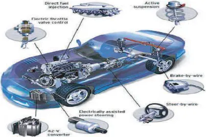
Figure 2.1: Automotive Applications For By Wire Technology
(Source: H. Inagaki et al. 1992)
The following is the chronological order of essential steps and breakthroughs in automotive steering system which indirectly created a path for the discovery of automatic steering system.
$ 5# !& 7' 66 6)'# )'' "