MODELING AND VALIDATION OF SIX-BAR RACK AND PINION
STEERING LINKAGE SYSTEM
Mohd Zakaria Mohammad Nasir1,a*, Mohd Zubir Amir2,b, Khisbullah Hudha3,c, Mohd Azman Abdullah4,d, Muhammad Zahir Hassan5,e, Masjuri Musa@Othman6,f
1,2,3,4,5,6Faculty of Mechanical Engineering, Durian Tunggal, Universiti Teknikal Malaysia Melaka. a
Email: [email protected],bEmail: [email protected],cEmail: [email protected], d
Email: [email protected],eEmail: [email protected],fEmail:[email protected]
Abstract— A vehicle handling behavior is much influenced
by the performance of steering system and its mechanism. Steering linkage play a very important role in maneuvering of a vehicle. In this paper, a planar six-bar rack and pinion steering linkage is modeled in MATLAB SIMULINK to study the relationship between steering wheel angle and tire angle. A set of kinematic relations of steering system is used to analyze the kinematics of a planar linkage. The steering system consists of rack and pinion, tie rod end, tire and
steering wheel column are modeled in MATLAB
SIMULINK environment based on kinematic model
equations is presented. The model is then validated using Hardware-in-the-loop simulations (HILS) consists of LVDT and rotary encoder sensors installed in actual steering system for data measurement at various steering angle.
Results from simulation model has been developed
demonstrates a linear pattern occurred from maximum lock-to-lock steering wheel angle and it’s closely follow the
trend through HILS experiment.
KeywordsRack and pinion; Steering linkage; HILS
(Hardware-in-the-loop simulation).
L. INTRODUCTION
Steering a car is a driver responsibility as guidance for motor vehicle direction. It involves the driver looking ahead at the intended path relative to the vehicle and somehow processing the preview information and the current position data to yield the steering wheel or control inputs needed to make the vehicle follow the desired path.
Steering linkages play a very importance role in maneuvering of a vehicle. Amongst the steering linkages, the rack and pinion steering linkage is the most popular and widely used in automotive passenger vehicle [1, 2, 5, 7]. Thus it is chosen in this study. This linkage consists of two steering arms (wheel knuckle), two tie rods end as well as a rack and pinion as depicted in Fig. 1.
The rack and pinion system convert the rotational motion of the steering wheel or driver input into linear motion required to turn the tire, and provide gear reduction or steering ratio, making easier to turn the tire. In most passenger vehicle, approximately three or four complete revolutions of steering wheel is required for the tire turn maximum lock-to-lock from far left to far right [5]. The pinion gear is directly attached to the steering shaft which connected to steering wheel. As a result, when the steering wheel is turned, the pinion turn which causes the rack move either left or right and as desired outcome, it causes the tires to turn in the desired direction.
In this paper, six bar rack and pinion type is modeled in MATLAB SIMULINK to predict the correlation between steering wheel angle, steering rack and tire angle.
Figure 1.The rack and pinion steering linkage system
II. STEERING LINKAGE KINEMATIC EQUATION
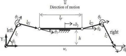
The rack and pinion linkages are complex and a spatial mechanism because of the parameter of caster angle and kingpin inclination is in XZ and YZ plane [2]. However, those parameters have little influence on the functionality of the steering linkage [3]. As suggested in literature [2, 4, 6], the caster angle and the kingpin inclination provided to correlate suspension and steering system can be neglected. Accordingly, the actual rack and pinion steering linkage can be modeled as a planar linkage as shown in Fig. 2. In this paper, only planar modeling is demonstrated for better understanding of the modeling approach.
Figure 2.Six-bar planar of rack and pinion steering linkage
The rack and pinion linkage model is formulated the kinematic equations as a six bar planar linkage [1]. The kinematic equation for the rack and pinion can be written in Eq. (1) below where wtis the wheel track,lr is rack
length andb1is the rack travel shown in Fig. 2.
1
2
t r
w l
From Fig. 2, it producesccosine andssine functions in
term of scalar components, wherehis distance from front
wheel axis, lt is tie rod length and l is steering arm length.
Equations (2) and (3) can be expressed as
T TThe value ofz1is the solution of a quadratic equation that obtained from the kinematic equations in Eq. (2) and Eq. (3). The equation can be written as
2 2 2
Accordingly,ș2is obtained from one of the Eq. (2)
and Eq. (3) by substitutingș1.To calculate theș6,
an expression similar to Eq. (1) is written from the right side links of the steering shown in Fig. 2.
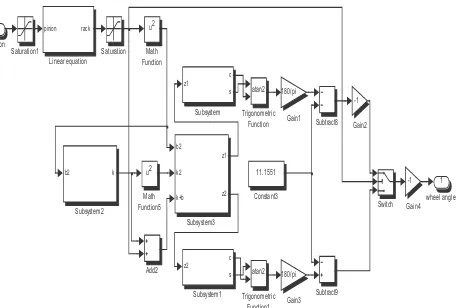
III. STEERING SYSTEM MODEL
The steering system is modeled in MATLAB
SIMULINK environment based on actual dimension of rack and pinion steering linkage from Malaysian National Car. The steering system model is developed based on the above equations. In this study, a planar model is developed for the standard configuration of the rack and pinion steering linkage by eliminating the kingpin inclination, caster angle and kingpin offset.
The mathematical modeling considered in this study consists of a DC motor model, rack and pinion model and
the kinematic model of the steering system. A motor actuator is modeled in this steering system to represented steering input. Fig. 3 shows the pinion as steering input and the wheel angle as an output which than function as an input for vehicle model. Some modeling assumptions considered in this study are as follows; the effect of steering inertia is neglected, the front left and front right wheels are assumed to have identical tire angle under excitation from steering input, the efficiency of the DC motor shaft to pinion rotating shaft is neglected.
1
Figure 3.Propose rack and pinion steering system modeled in MATLAB
IV. PERFORMANCE VALIDATION USINGHARDWARE
-IN-THE-LOOP SIMULATION TEST RIG
The relation between rotation of pinion and displacement of rack can be defined by perform an experimental on actual rack and pinion steering system through Hardware-in-the-loop simulation (HILS). The front tire is set in
normal position, and Linear Variable Differential
Transformer (LVDT) and rotary encoder sensors used for measurement. The DC motor is represented as an actuator to generate desired steering wheel angle and it allowed rotating about its rotational axis.
Figure 4.HILS set up for rack and pinion steering linkage
The output from both sensors (LVDT and rotary encoder) is transferred into XPC TARGET in Matlab software for data analysis. The output data from experiment will be compared with steering system model developed in MATLAB SIMULINK environment.
Position tracking of DC motor is required to perform prior test the actual six bar rack and pinion steering system. This is to ensure the control system design for motor is good enough to follow the desired steering input. Fig. 5 show the controller of DC motor was developed for position tracking in HILS testing. The test is performed on actual rack and pinion steering linkage with both tire contact on ground and carry 150kg load for engine weight representation.
XPC TARGET was used to perform model
identification for DC motor which must have the capabilities to run under various degree of steering input. Signal generator used to represent steering input such as
sine 30 means turn the steering wheel 30qclockwise and
anticlockwise. The desired steering position from the signal input given is compared with the actual angle position of the motor rotating shaft measured by rotary encoder, which results in position deviation error denoted
byea. The input signal of DC motor is voltage,U, which
is represented as the required rotational DC motor speed
that is commanded to a pulse generator’s block. The error is weighted by the control proportional gain, P, which resulting in voltage.
U= P.ea (11)
PCI 6221 ENC
-K-Figure 5.Position tracking controller developed for HILS
V. RESULT AND DISCUSSION
The position tracking test for DC motor is performed to ensure the motor can follow the desired steering input. When steering wheel is turned by giving input signal, the DC motor tend to follow the desired signal by rotating the pinion angle which than pull or push the tie rod end to turn the tires into the desired angle. Fig. 6 demonstrates the position tracking result for DC motor developed in XPC TARGET environment. It shows the actual rack and pinion measured through pinion angle closely follow the desired angle of steering input with acceptable error. Fig. 6 shows the example position tracking test for sine wave input for 30q. The control structure therefore can be used to test the six bar rack and pinion linkage system for various steering input.
0 2 4 6 8 10
Figure 6. Positioning tracking for DC motor
The result from simulation model is shown in Fig. 7. Y-axis represents the steering rack displacement and X-axis represents the pinion angle. The line in the plotted graph shows a slip behaviour of gear occurred. This is due to backlash in the gearbox of the steering linkage mechanism. To simplify the relationship between the rack and pinion steering mechanisms, the rack displacement is assumed directly proportional to the pinion rotational angle. The relationship is ; Y = 0.00005X – 0.001
Both result gathered from simulation and HILS testing for rack and pinion steering linkage system are shown in Fig. 8. The linear pattern occurred when the steering wheel is turning maximum lock-to-lock (610qclockwise and 610q anticlockwise). The grey line in the plotted graph shows a nonlinear behavior or slip angle from experimental occur at steering wheel rotated at 200q anticlockwise. This is due to backlash in the gearbox of the steering linkage mechanism. Gear pairs like rack and pinion have clearance between gear teeth matching called backlash. Backlash is clearance between mating components and as the amount of lost motion due to clearance or slackness. When pinion are rotated, slack will happen at a point where it has clearance between pinion and rack. This happen at the range of 22 mm to 25 mm as referred to Fig. 8.
-800 -600 -400 -200 0 200 400 600 800 -0.06
-0.04 -0.02 0 0.02 0.04 0.06
Steering angle (degree)
R
a
c
k
d
is
p
la
c
e
m
e
n
t
(m
)
Simulation Experiment
Figure 8: Relation of rack displacement and pinion angle in MATLAB
and HILS Steering System
From steering system model, the correlation between displacement of rack and wheel angle can be defined as shown in Fig. 9. The maximum length of LVDT for anticlockwise is 59.5 mm that provide 30.5qof tire angle.
Figure 9: Relation of rack displacement and tire angle in Steering System
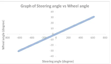
The relation of steering wheel angle and tire angle is shown in Fig. 10. It demonstrate the linear pattern line occur for maximum steering wheel angle turning from far left to far right. The maximum steering wheel is 610qfor anticlockwise resulting the of tire rotate about 30.5qfrom normal angle or longitudinal direction.
Figure 10: The relationship between tire angle and steering wheel angle in Steering System
VI.CONCLUSIONS
The entire steering linkage system is modeled in MATLAB SIMULINK environment which represents actual dimension based on kinematic equations. The relationship of steering rack displacement and pinion angle is achieved by perform simulation and experimental measurement for actual rack and pinion steering linkage system. A result from simulations demonstrates a linear pattern where it’s closely follows the trend occurred through experiment. The relation between rack displacement can be assumed directly proportional to the pinion angle with; Y = 0.00005X – 0.001. From the experiment data slack happens at range of 22 mm to 25 mm. The maximum rack displacement from normal position is 59.5 mm provide maximum wheel angle 30.5q.
ACKNOWLEDGMENT
This work is supported by the Universiti Teknikal Malaysia Melaka (UTeM) through FRGS-F0079 project
entitled “Developement Of Lateral and Longitudinal Driver Model for Autonomous Vehicle Control” and Short term grant (PJP)S742 namely ' Development of HIL on Automatic Steering System'. Both projects are lead by the first author. This financial support is
gratefully acknowledged.
REFERENCES
[1] A.Rahman Hanzaki, S.K.Saha, P.V.M.Rao, Modeling of Rack and Pinion Steering Linkage using Multi-Body Dynamics.12th International Federation for the Promotion of Mechanism and Machine Science Congress (IFToMM), Besancon, France, June 2007.
[2] Naresh Kamble and S.K. Saha, Developing a Virtual Prototype of Rack and Pinion Steering System, International Journal Vehicle System Modelling and Testing, Vol. 2, No.1, 2007. [3] Emm Ping, K.Hudha, Hisham Jamaludin,
[4] Emm Ping, K.Hudha, Hanif Harun, Hisham Jamaludin, Hardware-in-the-loop Simulation of Automatic Steering, IEEE International Conference on Control Automation, Robotics and Vision,2010.Singapore, pp. 964-969.
[5] Baxter, J., Wou, J. S., Oste, T. D. , Modeling of Mesh Friction and Mechanical Efficiency of Rack and Pinion Steering System, Steering and Suspension Technology Symposium, 2001, pp 45-56.
[6] T. G. Rao, S.K. Saha, I.N. Kar, Sensor-Actuator Based Smart Yoke for a Rack and Pinion Steering System, SAE International, SAE International, 2004