Hardware in the Loop Simulation of Active Front
Wheel Steering control for yaw disturbance rejection
Khisbullah Hudha*
Hang Tuah Jaya, 76100 Durian Tunggal, Melaka, MalaysiaE-mail: [email protected] E-mail: [email protected]
Abstract: This paper introduces an Active Front Wheel Steering (AFWS) control for the purpose of reducing unwanted yaw motion. Side wind forces are considered to be the sources of yaw disturbance in this study. The proposed control strategy for the AFWS is a lateral directional control with yaw rate feedback. The AFWS controller was implemented on Hardware in the Loop Simulation (HiLS) using an AFWS test rig. From the simulation and experimental results, AFWS control is able to perform the task of yaw disturbance attenuation by providing additional steering correction for maintaining the original direction of the vehicle.
Keywords: active front wheel steering; side wind force; yaw cancellation; HiLS; vehicle safety.
Reference to this paper should be made as follows: Hudha, K., Zakaria, M.H. and Tamaldin, N. (xxxx) ‘Hardware in the Loop Simulation of Active Front Wheel Steering control for yaw disturbance rejection’, Int. J. Vehicle Safety, Vol. x, No. x, pp.xxx–xxx.
Mohd. Hafiz Zakaria is a research Student in the Vehicle Dynamics Control Lab of Universiti Teknikal Malaysia Melaka. His current research project is to develop an Active Front Wheel Steering (AFWS) control for passenger vehicles. His research interests include tire modelling, vehicle ride and handling and steering system modelling and control.
Noreffendy Tamaldin received his BSc Degree in Mechanical Engineering (Honor: CUM Laude) and MEng Degree in Mechanical Engineering with specialisation in Mechatronics from the University of Hartford, Connecticut, United States, and his PhD Degree on Experimental Investigation of Emission from a Light Duty Diesel Engine Utilising Urea Spray SCR System from Coventry University, United Kingdom. His research interests include diesel after treatment, emission study, alternative fuels, hybrid technologies and engine performance study, simulation and validation. He is currently Attached with the Automotive Department, Universiti Teknikal Malaysia Melaka (UTeM). His profile can be reached at: http://www.utem.edu.my/fkm.
1 Introduction
Active Front Wheel Steering (AFWS) is an automotive mechatronics system, introduced by BMW in 2003, that has the capability of varying steering ratio for improving vehicle directional stability. Active Front Wheel Steering (AFWS) uses an electric motor to deliver steering correction to be superimposed with the existing conventional steering mechanism. In parking manoeuvres, this technology reduces the amount of the steering wheel input that must be given by the driver, since the electric motor varies the steering ratio so that the steering wheel needs less than two turns to move the wheels from lock to lock. At higher speeds, AFWS is used to improve vehicle directional stability by rejecting unwanted yaw motion. In automotive vehicles, side wind forces or poor road conditions can be the source of unwanted yaw disturbance. In this situation, AFWS will react based on the information from the yaw rate sensors or accelerometer mounted at the body Centre of Gravity (CoG) to modify the steering angle of the front wheels and stabilise the vehicle.
Preliminary works on the design of active steering systems can be found in various papers such as in Ackermann and Senel (2003), Zheng et al. (2004), Tomizuka and Hedrick (1995), Ono et al. (1996), Furukawa and Abe (1997). Recent attempts on improving vehicle dynamics performance using AFWS have been performed by using active disturbance rejection control (Yiran and Hui, 2010), µ−control (Chao-Chun et al., 2010), Optimal model following control (Li and Yu, 2009), yaw-rate control (Ando and Fujimoto, 2010), yaw stability control (Zheng and Anwar, 2009), model predictive control (Yoon et al., 2009), adaptive feedback control (Bianchi et al., 2010) and Robust anti-sliding control (Fang et al., 2011). All the recent works have claimed to have significant performance improvement compared with passive systems, as well as the ability to maintain the original direction of the vehicle in the presence of external yaw disturbance.
to move out of its lane, which degrades the stability and safety of the vehicle. This study focuses on the enhancement of vehicle directional stability of passenger vehicles using the AFWS control system by considering the side wind force as the source of disturbance. Lateral displacement control with yaw rate feedback is proposed to generate the optimum steering correction in cancelling the effects of the side wind force. Some criteria will be evaluated to study the performance of the proposed AFWS system involving lateral displacement error, vehicle side slip angle, yaw angle and yaw rate.
In this study, the proposed AFWS control is tested on both a 14 Degrees of Freedom (DOF) full vehicle model and Hardware in the Loop Simulation (HiLS). An AFWS actuator has been developed along with the AFWS test rig as the main components of the HiLS. HiLS is a technique used to simplify the development and testing of complex real-time embedded systems. HILS provides an effective platform by adding the complexity of the plant under control to the test platform. In HiLS, the AFWS actuator and the real conventional steering mechanism interact with the 14 DOF vehicle model via a Data Acquisition (DAQ) card and the necessary sensors. A side wind force is introduced in the 14 DOF model so that the need for an expensive wind burst generator can be avoided. By using HiLS, the performance of the AFWS controller and the functionality of the AFWS actuator can be evaluated without facing safety-related problems that may arise in implementing AFWS in a real vehicle.
This paper is organised as follows: The first section contains an introduction and the review of some relevant preliminary works, followed by the structure of the 14 DOF vehicle model in the second section. The third section introduces the disturbance modelling. The fourth section presents the controller structure of the active steering system, which consists of two controller loops, namely, the inner and outer loops. Hardware in the loop setup is presented in the fifth section. The results of simulation and experimental investigations are presented in the sixth section. The last section contains some conclusions.
2 Vehicle modelling
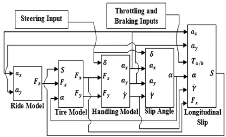
The full-vehicle model of the passenger vehicle considered in this study consists of a single sprung mass (vehicle body) connected to four unsprung masses, and is represented as a 14-DOF system. The sprung mass is represented as a plane and is allowed to pitch, roll and yaw as well as to displace in vertical, lateral and longitudinal directions. The unsprung masses are allowed to bounce vertically with respect to the sprung mass. Each wheel is also allowed to rotate along its axis and only the two front wheels are free to steer. Detail derivation of the 14-DOF vehicle model can be found in Hudha et al. (2008) and Ahmad et al. (2009, 2010). The model consists of three main subsystems, namely, the ride, handling and tire subsystems. Figure 1 shows the schematic diagram of the 14 DOF full vehicle model used in this study.
small. A similar model was used by Ikenaga et al. (2000). The handling model employed in this paper is also a 7-DOF system which takes into account three DOF for the vehicle body in lateral and longitudinal motions, as well as yaw motion, and one DOF due to the rotational motion of each tire. In the vehicle handling model, it is assumed that the vehicle is moving on a flat road.
Figure 1 Vehicle model subsystems with 14 DoF
Some of the modelling assumptions considered in this study are as follows: the vehicle body is lumped into a single mass which is referred to as the sprung mass, aerodynamic drag force is ignored, and the roll centre is coincident with the pitch centre and located at just below body CoG. The suspensions between the sprung mass and unsprung masses are modelled as passive viscous dampers and spring elements. Rolling resistance due to the passive stabiliser bar and body flexibility are neglected. The vehicle remains grounded at all times, and the four tires are always in contact with the ground during manoeuvring. A four degree tilt angle of the suspension system about the vertical axis is neglected (since cos 4 = 0.998 ≈ 1). Tyre vertical behaviour is represented as a linear spring without damping, whereas the lateral and longitudinal behaviours are represented with the Calspan model. The steering system is modelled as a constant ratio, and the effect of steering inertia is neglected.
3 Disturbance modelling
1 2
z
s s s
F = ρ C A V
where Fs is the side wind force, ρ is air density, which is normally set to 1.206 kg/m3, and V is air speed relative to the vehicle. Cs is the side force coefficient and As is the vehicle side area. The side wind force acts on the vehicle body at the centre of pressure, which is located ahead of the body CoG. The distance between the centre of pressure and the body CoG results in an overturning moment and yaw moment whenever the side wind force is present. In this study, the wind speed is defined as a step function, with the wind speed magnitude of 75 km/h and 100 km/h, as shown in Figure 2.
Figure 2 Wind speed relative to the vehicle
4 Control structure
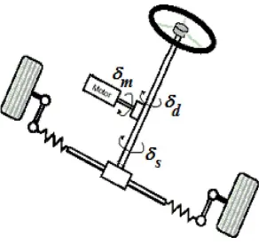
The AFWS system realises front-wheel steering control by superimposing active steering correction from the electric motor with the steering-wheel input from the driver, as shown in Figure 3. The AFWS system is developed by maintaining the existing mechanical steering linkages with the additional planetary gear set. The function of the planetary gear set is to superimpose the rotational input from the electric motor and the rotational input of the steering column. It is necessary to note that the AFWS system will start to function if the vehicle begins to yaw without any steering wheel input from the driver. Otherwise, the AFWS system will be off.
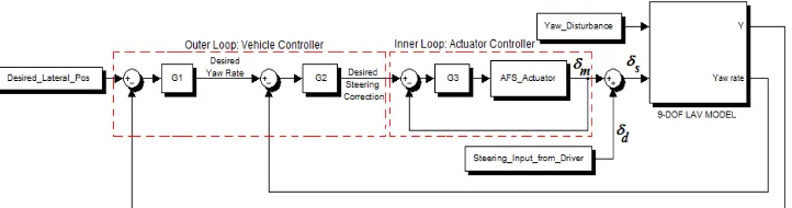
The proposed control structure for the AFWS system is shown in Figure 4. The control structure consists of two controller loops, namely, the outer and inner loops controller. The outer loop controller is used to reject unwanted yaw disturbance, and is known as vehicle controller. The inner loop controller is used to control the AFWS actuator in such a way that the AFS actuator will generate the steering input as commanded by the outer loop controller. For the outer loop controller, lateral position control and yaw rate feedback control are combined serially to get an accurate steering command in rejecting yaw disturbance. In the inner loop controller, a simple PID controller is used to control the DC motor of the AFWS actuator.
Figure 4 Control structure for AFWS system (see online version for colours)
In the outer loop controller, the output of the lateral position control is the desired yaw rate ϕd in opposing the unwanted yaw motion, and is defined as follows:
1
( )
d yd y G
ϕ = − (1)
where yd is the desired lateral displacement, y is the actual lateral displacement and G1 is
the lateral displacement controller. The desired yaw rate is used as the reference for the second loop in the outer loop controller, namely, yaw rate feedback control. The output of the yaw rate feedback control is the desired steering correction from the electric motor
δmd and is given by
The desired steering correction from the electric motor δmd should be tracked by the inner loop controller in such a way that the AFWS actuator is able to deliver steering correction as commanded by the outer loop controller. The steering correction from the AFWS actuator is computed using the following formula:
3 4
actuator. Finally, the total steering input of the steering shaft or steering pinion δs is superimposed between steering input from the driver δd and steering correction from the AFWS actuator δm and is given by
.
s m d
5 Hardware in the loop setup
5.1 Actuator design
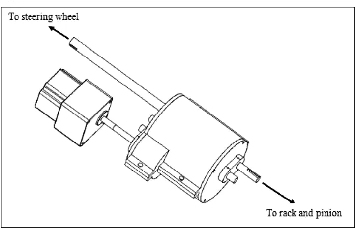
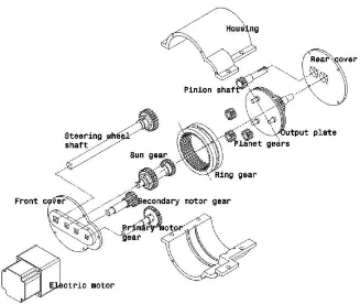
The AFWS actuator has been designed with the function of superimposing the steering correction from the AFWS controller with the steering input from the driver. Since most of the current stock vehicles are equipped with Electronic Power Steering (EPS) systems, the AFWS actuator is positioned in the steering column, since the steering column has available space for installing a new system. This also avoids adding to the complexity of the AFWS design or any unwanted interaction between the AFWS and EPS systems. Figure 5 shows the assembly drawing of the AFWS actuator, which has two input shafts and a single output shaft. The first input shaft is connected to the steering wheel and the second input shaft is connected to the electric motor, whereas, the output shaft is directly connected to the rack and pinion system.
Figure 5 AFWS actuator
Figure 6 Exploded view of AFWS actuator
If the AFWS system fails to function, the driver is still able to control the vehicle as in a conventional steering system. Since a permanent magnet motor has the same torque behaviour during static and dynamic conditions, the motor will hold the ring gear to let the sun gear and planet gears rotate according to the driver’s input, as in a normal steering system. This will let the driver manoeuvre the vehicle without the need for assistance from the AFWS actuator. The AFWS actuator also has an on/off switching function in which the AFWS system will only go active when there is no steering input from the driver, and at the same time, the gyro-rate sensor and the accelerometer detect a change in yaw rate and lateral position of the vehicle cause by side wind disturbance. 5.2 HiLS test rig
The performance of the proposed AFWS system controller is investigated in both simulation and experimental studies using HiLS. HILS is necessary for the development of modern vehicle handling dynamic controllers, which can be regarded as a standard method (Schuette and Waeltermann, 2005). HiLS is defined as the middle step between vehicle field tests and simulation studies (Seungkyu et al., 2009). HILS is simulated using xPC-TARGET and REAL-TIME WORKSHOP of the MATLAB software package to validate between experimental and simulation data. For the purpose of comparison, the performance of the proposed controller is also compared with the passive conventional steering system.
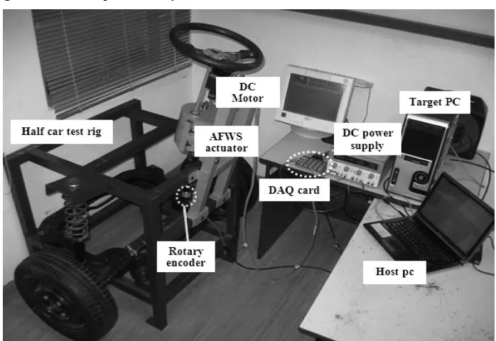
a passenger vehicle: the electric motor, the switching driver circuit, the rotary encoder, the DAQ PCI card, the PCI-based network card, the crossover network cable, the host PC, the target PC, DC power supply and the input/output pinout board. Software parts include signal interface between the host PC and the target PC, xPC TARGET and REAL-TIME WORKSHOP software to control the electric motor, Visual Studio 2008 Express as a C compiler, input/output signals on the pinout and the AFWS controller. The target PC for this system was a Pentium 4 with 256 MB RAM. Figure 7 shows the HiLS setup on the AFWS system test rig.
Figure 7 HiLS setup of AFWS system
6 Simulation and experimental results
Simulation and experimental evaluation using HiLS were performed in a Matlab Simulink environment for three different cases, namely: Case 1 for vehicle speed 90 km/h and wind speed 100 km/h; Case 2 for vehicle speed 110 km/h and wind speed 100 km/h; and Case 3 for vehicle speed 110 km/h and wind speed 75 km/h. The three cases were selected to study the effects of varying both vehicle and wind speed on the performance of the AFWS controller. In this study, five performance criteria are analysed, namely, steering position tracking performance, lateral displacement error, vehicle side slip angle, yaw angle and yaw rate. Tire, vehicle and simulation parameters were adopted from Hudha et al. (2008) and Ahmad etal. (2009, 2010).
6.1 Case 1: vehicle speed 90 km/h and wind speed 100 km/h
In case 1, the vehicle speed and the magnitude of wind speed were set to 90 km/h and 100 km/h, respectively. Figure 8 shows the position tracking control performance of the steering system. The desired steering correction is defined as the steering input that must be delivered by the electric motor to attenuate unwanted yaw disturbance. The desired steering correction was obtained from the simulation result. Actual steering correction is the steering input produced by the real steering mechanism in the HiLS of the AFWS system. It can be seen that the HiLS is able to generate the actual steering correction close to the desired one. Both the trend and the magnitude of the actual and desired steering corrections are closely similar.
Figure 8 Position tracking performance of the steering system for vehicle speed 90 km/h and wind speed 100 km/h (see online version for colours)
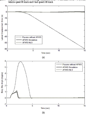
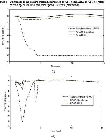
simulation and HiLS is able to maintain the desired direction of travel with minimum lateral displacement error, as shown in Figure 9(a). In terms of body slip angle, the vehicle with AFWS system is able to reduce the magnitude of body slip to about one-sixth of that for the conventional steering system, as shown in Figure 9(b). In terms of yaw rate and yaw angle response, the AFWS controller shows significant improvement compared to the passive conventional steering system, as shown in Figure 9(c) and (d). It indicates that the AFWS control is able to significantly reject unwanted yaw motion due to the side wind force. Agreement between simulation and HiLS in lateral displacement error, body slip angle, yaw and yaw rate responses is also clearly seen.
Figure 9 Responses of the passive steering, simulation of AFWS and HiLS of AFWS system for vehicle speed 90 km/h and wind speed 100 km/h
(a)
Figure 9 Responses of the passive steering, simulation of AFWS and HiLS of AFWS system for vehicle speed 90 km/h and wind speed 100 km/h (continued)
(c)
(d)
6.2 Case 2: vehicle speed 110 km/h and wind speed 100 km/h
Figure 10 Position tracking performance of the steering system for vehicle speed 110 km/h and wind speed 100 km/h (see online version for colours)
The performance of the AFWS control in reducing unwanted yaw disturbance for a vehicle speed of 110 km/h and a wind speed of 100 km/h is shown in Figure 11. Again, a vehicle with a conventional steering system displaces laterally about 40 m at the end of the simulation, and a vehicle with AFWS system in both simulation and HiLS is able to maintain the desired direction of travel with minimum lateral displacement error, as shown in Figure 11(a). In terms of body slip angle, yaw rate and yaw angle response, the AFWS controller shows noteworthy improvement compared to the conventional steering system, as shown in Figure 11(b)–(d). It indicates that the AFWS control is able to significantly reject unwanted yaw motion due to the side wind force. Agreement between simulation and HiLS in lateral displacement error, body slip angle, yaw and yaw rate responses is also noted.
Figure 11 Responses of the passive steering, simulation of AFWS and HiLS of AFWS system for vehicle speed 110 km/h and wind speed 100 km/h
Figure 11 Responses of the passive steering, simulation of AFWS and HiLS of AFWS system for vehicle speed 110 km/h and wind speed 100 km/h (continued)
(b)
(c)
(d)
6.3 Case 3: vehicle speed 110 km/h and wind speed 75 km/h
correction is needed with the decreasing of wind speed. It can be noted that the HiLS is able to generate the actual steering correction close to the desired one. Both the trend and the magnitude of the actual and desired steering corrections are closely similar. Again, noise from the actual steering correction response can be eliminated by implementing a proper filtering method.
Figure 12 Position tracking performance of the steering system for vehicle speed 110 km/h and wind speed 75 km/h
The performance of the AFWS control in reducing unwanted yaw disturbance for a vehicle speed of 110 km/h and a wind speed of 75 km/h is shown in Figure 13. Again, a vehicle with conventional steering system displaces laterally about 4.5 m at the end of the simulation, and a vehicle with AFWS system in both simulation and HiLS is able to maintain the desired direction of travel with minimum lateral displacement error, as shown in Figure 13(a). In terms of body slip angle, yaw rate and yaw angle response, the AFWS controller shows superior performance compared to the conventional steering system, as shown in Figure 13(b)–(d). It indicates that the AFWS control is able to significantly reject unwanted yaw motion due to the side wind force. Agreement between simulation and HiLS in lateral displacement error, body slip angle, yaw and yaw rate responses is also noted.
Figure 13 Responses of the passive steering, simulation of AFWS and HiLS of AFWS system for vehicle speed 110 km/h and wind speed 75 km/h
Figure 13 Responses of the passive steering, simulation of AFWS and HiLS of AFWS system for vehicle speed 110 km/h and wind speed 75 km/h (continued)
(b)
(c)
7 Conclusions
A lateral directional control with yaw rate feedback has been developed for AFWS control of passenger vehicles for the purpose of cancelling out unwanted yaw moment due to any side wind force. From the simulation results with three different cases, it can be concluded that the performance of the proposed AFWS controller is superior compared to conventional steering systems. The proposed controller of the AFWS system has also been tested in hardware in a loop simulation environment for bridging the gap between pure simulation and on the road test. As part of the HiLS hardware, an AFWS actuator and an AFWS test rig have also been developed in this study. From the experimental results, it can be concluded that there is a good agreement between simulation and HiLS of AFWS system in terms of lateral displacement error, body slip angle, yaw and yaw rate responses.
References
Ackermann, J. and Sienel, W. (1993) ‘Robust yaw damping of cars with front and rear wheel steering’, IEEE Transactions on Control Systems Technology, Vol. 1, No. 1, pp.15–20. Ahmad, F., Hudha, K. and Jamaluddin, H. (2009) ‘Gain scheduling PID control with pitch moment
rejection for reducing vehicle dive and squat’, Int. J. of Vehicle Safety 2009, Vol. 4, No. 1, pp.45–83.
Ahmad, F., Hudha, K., Imaduddin, F. and Jamaluddin, H. (2010) ‘Modelling, validation and adaptive PID control with pitch moment rejection of active suspension system for reducing unwanted vehicle motion in longitudinal direction’, International Journal of Vehicle Systems Modeling and Testing, Vol. 5, No. 4, pp.312–346.
Ando, N. and Fujimoto, H. (2010) ‘Yaw-rate control for electric vehicle with active front/rear steering and driving/braking force distribution of rear wheels’, 11th IEEE International Workshop on Advanced Motion Control, Nagaoka, Japan, 21–24 March, pp.726–731.
Bianchi, D., Borri, A., Benedetto, M.D.D., Gennaro, S.D. and Burgio, G. (2010) ‘Adaptive integrated vehicle control using active front steering and rear torque vectoring’, International Journal of Vehicle Autonomous Systems, Vol. 8, Nos. 2–4, pp.85–105.
Chao-chun, Y., Long, C., Shao-hua, W. and Hao-bin, J. (2010) ‘Robust active front steering control based on the mu control theory’, International Conference on Electrical and Control Engineering (ICECE), Wuhan, China, 25–27 June, pp.1827–1829.
Fang, H., Dou, L., Chen, J., Lenain, R., Thuilot, B. and Martinet, P. (2011) ‘Robust anti-sliding control of autonomous vehicles in presence of lateral disturbances’, Control Engineering Practice, Vol. 19, No. 5, pp.468–478.
Furukawa, Y. and Abe, M. (1997) ‘Advanced chassis control systems for vehicle handling and safety’, Vehicle System Dynamics, Vol. 28, pp.59–86.
Gillespie, T.D. (1992) Fundamentals of Vehicle Dynamics, SAE International. AUTHOR PLEASE SUPPLY FULL DETAILS.
Hudha, K., Jamaluddin, H. and Samin, P.M. (2008) ‘Disturbance rejection control of a light armoured vehicle using stability augmentation based active suspension system’, Int. J. Heavy Vehicle Systems, Vol. 15, Nos. 2–4, pp.152–169.
Ikenaga, S., Lewis, F.L., Campos, J. and Davis, L. (2000) ‘Active suspension control of ground vehicle based on a full-vehicle model’, Proceedings of American Control Conference, Vol. 6, pp.4019–4024.
Ono, E., Hosoe, S., Tuan, H. D. and Doi, S. (1996) ‘Robust stabilization of vehicle dynamics by active front wheel steering control’, Proceedings of the 35th IEEE Conference on Decision and Control, 11–13 December, Kobe, Japan.
Schuette, H. and Waeltermann, P. (2005) Hardware-in-the-Loop Testing of Vehicle Dynamics Controllers – A Technical Survey, SAE Technical Paper Series, Paper No. 2005-01-1660. Seungkyu, O., Hyoungsoo, K. and Jinhee, J. (2009) ‘Proposals for improvement of AFS system
using HIL and SIL simulation’, ICROS-SICE International Joint Conference 2009, Fukuoka International Congress Center, 18–21 August, Japan, pp.555–559.
Tomizuka, M. and Hedrick, J.K. (1995) ‘Advanced control methods for automotive applications’, Vehicle System Dynamics: International Journal of Vehicle Mechanics and Mobility, Vol. 24, Nos. 6–7, pp.449–468.
Yiran, L. and Hui, C. (2010) ‘Application of active disturbance rejection control strategy for active front wheel steering control’, International Conference on Mechanic Automation and Control Engineering (MACE), Wuhan, China, 26–28 June, pp.3566–3569.
Yoon, Y., Shin, J., Kim, H.J., Park, Y. and Sastry, S. (2009) ‘Model-predictive active steering and obstacle avoidance for autonomous ground vehicles’, Control Engineering Practices, Vol. 17, No. 7, pp.741–750.
Zheng, B. and Anwar, S. (2009) ‘Yaw stability control of a steer-by-wire equipped vehicle via active front wheel steering’, Mechatronics, Vol. 19, No. 6, pp.799–804.