MINIATURIZATION OF RECTANGULAR MICROSTRIP ANTENNA
MUHAMAD HAFIZ BIN BAHARUN
This report is submitted in partial fulfilment of the requirements for the award of Bachelor of Electronic Engineering (Telecommunication Electronics) With Honours
Faculty of Electronic and Computer Engineering Universiti Teknikal Malaysia Melaka
ii
MUHAMAD HAFIZ BIN BAHARUN
UNIVERSTI TEKNIKAL MALAYSIA MELAKA
FAKULTI KEJURUTERAAN ELEKTRONIK DAN KEJURUTERAAN KOMPUTER
BORANG PENGESAHAN STATUS LAPORAN PROJEK SARJANA MUDA II
Tajuk Projek : MINIATURIZATION OF RECTANGULAR MICROSTRIP ANTENNA
Sesi
Pengajian : 2008/2009
Saya ……….
(HURUF BESAR)
mengaku membenarkan Laporan Projek Sarjana Muda ini disimpan di Perpustakaan dengan syarat-syarat kegunaan seperti berikut:
1. Laporan adalah hakmilik Universiti Teknikal Malaysia Melaka.
2. Perpustakaan dibenarkan membuat salinan untuk tujuan pengajian sahaja.
3. Perpustakaan dibenarkan membuat salinan laporan ini sebagai bahan pertukaran antara institusi pengajian tinggi.
4. Sila tandakan ( √ ) :
SULIT*
(Mengandungi maklumat yang berdarjah keselamatan atau kepentingan Malaysia seperti yang termaktub di dalam AKTA RAHSIA RASMI 1972)
TERHAD* (Mengandungi maklumat terhad yang telah ditentukan oleh
organisasi/badan di mana penyelidikan dijalankan)
TIDAK TERHAD
Disahkan oleh:
__________________________ ___________________________________
(TANDATANGAN PENULIS) (COP DAN TANDATANGAN PENYELIA)
Alamat Tetap: 5, JLN PADI MALINJA 2,
BDR BARU UDA , TAMPOI
81200 JOHOR
iii
“I hereby declare that this report is the result of my own work except for quotes as cited in the reference.”
Signature : ... Author : MUHAMAD HAFIZ BIN BAHARUN
iv
“I hereby declare that I have read this report and in my opinion this report is
sufficient in terms of the scope quality for the award of Bachelor of Electronic
Engineering (Telecommunication Electronics) With Honours.”
v
Special dedication to my loving parents, Baharun Bin Maulud and
Rohana Binti Ahmad, my kind-hearted supervisor, Mr. Abd Shukur Bin Ja’afar, and
vi
ACKNOWLEDGEMENTS
First and foremost, all the praise for AδδAH, without His permission, I won‟t be able to complete this project. I would like to express my highest gratitude to my
supervisor, εr. Abd Shukur Bin Ja‟afar for his patience, all his guidance, and
vii
ABSTRACT
viii
ABSTRAK
ix
TABLE OF CONTENT
CHAPTER TOPIC PAGE
PROJECT TITLE i
APPROVAL STATUS REPORT FORM ii
DECLARATION iii
ACKNOWLEDGEMENT vi
ABSTRACT vii
ABSTRAK viii
TABLE OF CONTENT ix
LIST OF TABLES xii
LIST OF FIGURES xiii
LIST OF ABBREVIATIONS xvi
LIST OF APPENDIX xvii
1 INTRODUCTION 1
1.1 Background 1
1.2 Project Objectives 2
1.3 Problem Statement 2
1.4 Scope of Work 3
1.5 Methodology 3
1.6 Report Structure 4
2 LITERATURE REVIEW 5
x
2.1.1 Basic Characteristic 5
2.1.2 Fringing Effects 7
2.1.3 Calculation of microstrip antenna 9 2.1.4 Calculation of λ/4 Transformation 12
2.2 Antenna Properties 13
2.2.1 Gain 13
2.2.2 Bandwidth 14
2.2.3 Radiation Pattern 15
2.2.4 Polarization 16
2.2.5 Beamwidth 17
2.3 Fractal Antenna 19
2.3.1 Introduction 19
2.3.2 Transformation of Fractal Geometry 22
2.4 Power Divider 23
2.5 Arrays 24
3 Project Methodology 25
3.1 Phase of Methodology 25
3.1.1 Project Planning 25
3.1.2 Literature Review 26
3.1.3 Designing 26
3.1.4 Fabrication 27
3.2 Project‟s Flow Chart 28
4 RESULTS AND DISCUSSION 29
4.1 Calculation of simple RMSA 29
4.2 Simulation Results 35
4.2.1 Simulation of the 1st iteration of the Minkowski fractal (ρ = 0.5)
xi
4.2.2 Simulation of the 1st iteration of the Minkowski fractal (ρ = 0.6)
37
4.2.3 Simulation of the 1st iteration of the Minkowski fractal (ρ = 0.7)
40
4.2.4 Simulation of the 1st iteration of the Minkowski fractal (ρ = 0.8)
42
4.2.5 Simulation of the 2nd iteration of the
εinkowski fractal (ρ = 0.5)
45
4.3 Discussion 48
5 CONCLUSION AND SUGGESTION 50
5.1 Conclusion 50
5.2 Suggestion 51
xii
LIST OF TABLES
NO TOPIC PAGE
2.1 Application of Microstrip Antenna 7
xiii
LIST OF FIGURES
NO TOPIC PAGE
2.1 Microstrip Antenna Configurations 6 2.2 Microstrip antenna and coordinate system 8 2.3 (a) Microstrip line (b) Electric field lines 9
(c) Effective dielectric constant geometry
2.4 Dimension of microstrip antenna 11
2.5 Calculator Tool in Microwave Office Software 11
2.6 Calculator tool in ADS Software 11
2.7 Dimension of quarter wave transformer 12 2.8 Radiation pattern of horn and dipole antenna 16 2.9 Three dimensional and two dimensional views of 17
power patterns
2.10 Radiation pattern 18
2.11 The first few stages in construction of a Elilbert curve 20 2.12 Some common fractal geometries found in 21
antenna applications: Koch snowflakes/islands
xiv
used in miniaturized dipole antennas
2.14 Some common fractal geometries found in antenna 21 applications: Sierpinski gaskets and carpet, used in
multi-band antennas
2.15 First Iteration 22
2.16 Power division and combining 23
2.17 λ/4 impedance transformers lines to match 100Ω patches 24
to a 50Ωline
3.1 Iteration process from 1st iteration until 3rd iteration 26
3.2 Designs of 2 ways power divider
3.3 Flow Chart 28
4.1 Square patch dimension 32
4.2 Calculator tool in Microwave office 33 4.3 Result obtained by using calculator tool in 33
Microwave office
4.4 Rectangular Microstrip Antenna 34
4.5 1stiteration of ρ = 0.5 35
4.6 Return loss of the 1stiteration of ρ = 0.5 35 4.7 Smith chart of the 1st iteration of ρ = 0.5 36 4.8 Side view of Far Field of the 1stiteration of ρ = 0.5 36 4.9 Top view of Far Field of the 1stiteration of ρ = 0.5 37
4.10 1stiteration of ρ = 0.6 37
xv
4.15 1stiteration of ρ = 0.7 40
4.16 Return loss of the 1stiteration of ρ = 0.7 40 4.17 Smith chart of the 1stiteration of ρ = 0.7 41 4.18 Top view of Far Field of the 1stiteration of ρ = 0.7 41 4.19 Side view of Far Field of the 1stiteration of ρ = 0.7 42
4.20 1stiteration of ρ = 0.8 42
4.21 Return loss of the 1stiteration of ρ = 0.8 43 4.22 Smith chart of the 1stiteration of ρ = 0.8 43 4.23 Top view of Far Field of the 1stiteration of ρ = 0.8 44 4.24 Side view of Far Field of the 1stiteration of ρ = 0.8 44
4.25 2nd iteration of ρ = 0.5 45
4.26 Return loss of the 1stiteration of ρ = 0.5 45 4.27 Smith chart of the 2nd iteration of ρ = 0.5 46 4.28 Side view of Far Field of the 2nd iteration of ρ = 0.5 46 4.29 Top view of Far Field of the 2nd iteration of ρ = 0.5 47
xvi
LIST OF ABBREVIATION
ADS Advance Design System
BW Bandwidth
dB Decibel
FNBW First Null Beamwidth
HPBW Half Power Beamwidth
ISM BAND Industrial, Scientific, and Medical Band
xvii
LIST OF APPENDIX
1
CHAPTER 1
INTRODUCTION
This topic consists of the introduction to the project, the background, project objective, problems statement, the scope of works covered.
1.1 Background
2
types of antenna such as smart antenna, horn antenna, parabolic antenna, Yagi-Uda beam antenna and etc.
Physically, an antenna is an arrangement of conductors that generate a radiating electromagnetic field in response to an applied alternating voltage and the associated alternating electric current, or can be placed in an electromagnetic field so that the field will induce an alternating current in the antenna and a voltage between its terminals. Therefore antenna has a wide area of application and is very important in our everyday life.
1.2 Project Objectives
There are three main objectives of this project which are:
a) To design and simulate Minkowski fractal antenna that will operate at 2.4 GHz within ISM band by using ADS.
b) To fabricate RMSA on the FR4 board by using etching technique.
c) To compare the analysis results obtained from simulation and fabricated RMSA.
1.3 Problem Statement
3
1.4 Scope of Work
There are several areas that have been identified or considered that need to be work out. There are:
a) Calculate the specification of the RMSA with the aid of MathCAD Calculation on the width and length of the radiating patch
b) Design, simulate, and analyze the RMSA and Minkowski fractal patch using ADS software. From simulation the antenna properties that can be analyzed such as return loss, radiation pattern, and so on.
c) Fabricate on the FR4 board using etching technique d) Compare analysis results of simulation and experimental
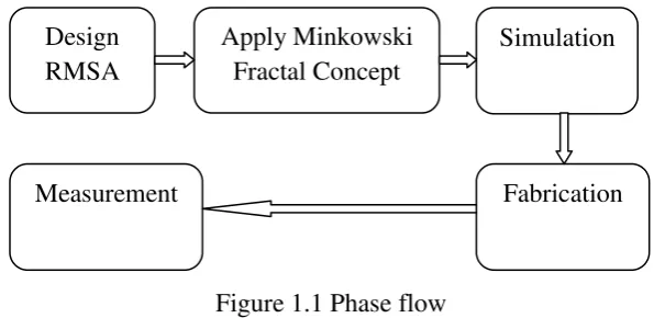
1.5 Methodology
[image:20.595.168.466.586.731.2]There are 5 important phases involved in order to achieve the objective of this project which are:
Figure 1.1 Phase flow
Further explanations of these phases will be discussed later on in chapter 3. Design
RMSA
Apply Minkowski Fractal Concept
Simulation
4
1.6 Report Structure
This thesis consists of five main chapters. The following are the outline of each chapter.
Chapter 1: This chapter is brief overviews of the project consist of introduction, background, project objective, problems statement, and scope of the project.
Chapter 2: This chapter discuss the research and information regarding the project. Facts and information gathered from journals and other resources is used to select the best methods for this project.
Chapter 3: This chapter is about the project methodology used for this project.
Chapter 4: This chapter discuss the project findings including results and discussions.
5
CHAPTER 2
LITERATURE REVIEW
This chapter will discuss precisely about the project, including the factors that should be considered before choosing a substrate, method for miniaturizing the antenna, configuration of an array antenna, and the antenna properties.
2.1 Microstrip Antenna
2.1.1 Basic Characteristic
6
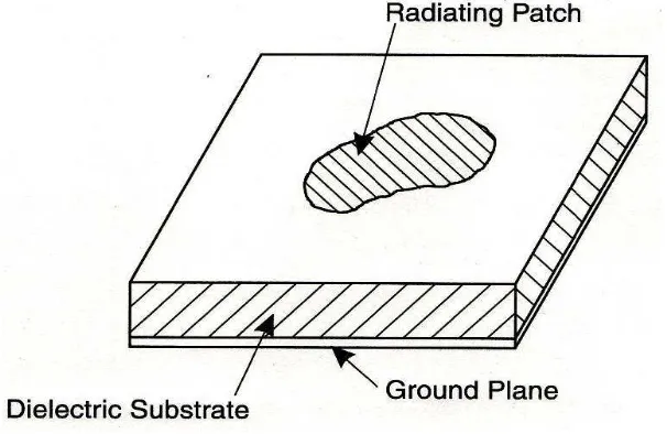
[image:23.595.114.417.299.496.2]are numerous substrates that can be used for the design of microstrip antennas, and their dielectric constants are usually in the range of 2.2 ≤ r ≤ 12. The ones that are most desirable for good antenna performance are thick substrates whose dielectric constant is in the lower end of the range because they provide better efficiency, larger bandwidth, loosely bound fields for radiation into space, but at the expense of larger element size. Thin substrates with higher dielectric constants are desirable for microwave circuitry because they require tightly bound fields to minimize undesired radiation and coupling, and lead to smaller element sizes; however, because of their greater losses, they are less efficient and have relatively smaller bandwidths [2].
Figure 2.1 Microstrip Antenna Configurations
The patch conductor is usually copper or gold. Microstrip patch antenna possibly can have various shapes, but regular shapes are commonly used to simplify analysis and to predict performance[1]. Below are the principle advantages of the microstrip antennas over conventional microwave antennas[1]:
Light weight, low volume, and thin profile configurations, which can be made conformal;
7
No cavity backing is required;
Can be easily integrated with microwave integrated circuits;
Feed lines and matching networks can be fabricated simultaneously with the antenna structure.
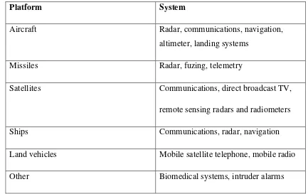
[image:24.595.100.533.277.550.2]The microstrip antenna is small in size, so it can be used in many area of application. Some of the applications are [4]:
Table 2.1 Application of Microstrip Antenna
Platform System
Aircraft Radar, communications, navigation,
altimeter, landing systems
Missiles Radar, fuzing, telemetry
Satellites Communications, direct broadcast TV,
remote sensing radars and radiometers
Ships Communications, radar, navigation
Land vehicles Mobile satellite telephone, mobile radio
Other Biomedical systems, intruder alarms