DESIGN OF PROXIMITY MICROSTRIP ANTENNA
NOR SUZYLIANA BINTI AHMAD
ii
DESIGN OF PROXIMITY MICROSTRIP ANTENNA
NOR SUZYLIANA BINTI AHMAD
This report is submitted in partial fulfillment of requirements for the award of Bachelor of Electronic Engineering (Telecommunication Electronics Engineering) With Honours.
Faculty of Electronic and Computer Engineering Universiti Teknikal Malaysia Melaka
iii
UNIVERSTI TEKNIKAL MALAYSIA MELAKA
FAKULTI KEJURUTERAAN ELEKTRONIK DAN KEJURUTERAAN KOMPUTER
BORANG PENGESAHAN STATUS LAPORAN PROJEK SARJANA MUDA II
Tajuk Projek : DESIGN A PROXIMITY MICROSTRIP ANTENNA
Sesi
Pengajian : 2007/2008
Saya NOR SUZYLIANA BINTI AHMAD
mengaku membenarkan laporan Sarjana Muda ini disimpan di Perpustakaan dengan syarat-syarat kegunaan seperti berikut:
1. Laporan adalah hakmilik Universiti Teknikal Malaysia Melaka.
2. Perpustakaan dibenarkan membuat salinan untuk tujuan pengajian sahaja.
3. Perpustakaan dibenarkan membuat salinan laporan ini sebagai bahan pertukaran antara institusi pengajian
tinggi.
4. Sila tandakan ( ) :
SULIT*
(Mengandungi maklumat yang berdarjah keselamatan atau kepentingan Malaysia seperti yang termaktub di dalam AKTA RAHSIA RASMI 1972)
TERHAD* (Mengandungi maklumat terhad yang telah ditentukan oleh
organisasi/badan di mana penyelidikan dijalankan)
TIDAK TERHAD
Disahkan oleh:
__________________________ ___________________________________
(TANDATANGAN PENULIS) (COP DAN TANDATANGAN PENYELIA)
Alamat Tetap: D/A PEGAWAI PENGANGKUTAN, BN 6 PGA, 84000 MUAR, JOHOR
iv
“I hereby declare that this report is the result of my own work except for quotes as cited in the references”.
v
“I hereby declare that I have read this report and in my opinion this report is sufficient in terms of the scope and quality for the award of Bachelor of Electronic Engineering
(Telecommunication Electronics Engineering) With Honours.”
Signature : ………
Supervisor’s Name : Mohamad Zoinol Abidin Bin Abd Aziz
vi
vii
ACKNOWLEDGEMENTS
My first thanks for my supervisor, Mr. Mohamad Zoinol Abidin Bin Abd. Aziz, whose constant support, patience and unbounded enthusiasm were of invaluable help. His devotion to the needs of the students and the encouragements have made working with him a true delight. Thanks for helping me to kick start this research by providing insights and his work as reference.
viii
ABSTRACT
ix
ABSTRAK
Komunikasi tanpa wayar beroperasi pada frekuensi 2.4GHZ. Kajian yang dijalankan adalah tentang Proximity Micro strip Antenna yang beroperasi pada frekuensi
WLAN. Projek ini merangkumi 2 jenis kaedah perambatan isyarat iaitu inset fed dan
proximity menggunakan antenna microstrip. Antara parameter yang dititikberatkan di dalam projek ini termasuk kehilangan kuasa, bentuk radiasi, lebar jalur, half power bandwidth (HPBW), first null bandwidth (FNBW), dan gandaan kuasa. Projek ini juga melibatkan proses simulasi, fabrikasi dan pengujian ke atas setiap rekabentuk antenna. Teknik inset fed dan Proximity Coupled Microstrip Antenna,PCMA direkabentuk menggunakan perisian microwave office. Rekabentuk inset fed menghasilkan kehilangan kuasa sebanyak -19dB dan teknik PCMA menghasilkan kehilangan kuasa paling minimum iaitu sebanyak -29dB. Ciri istimewa dalam antenna microstrip ialah melalui konsep array. Rekabentuk array untuk PCMA termasuk susunan 1x2, 1x4 and 2x4. Rekabentu 2x4 menghasilkan lebar jalur yang paling baik hingga mencapai 25%. Antena
x
CONTENT
CHAPTER TITLE PAGE
PROJECT TITLE ii
DECLARATION I iv
DECLARATION II v
DEDICATION vi
ACKNOWLEDGEMENT vii
ABSTRACT viii
ABSTRAK ix
CONTENT x
LIST OF TABLE xiv
LIST OF FIGURE xv
LIST OF ABBREVIATIONS xviii
LIST OF APPENDIX xx
I INTRODUCTION
1.1 Introduction 1
1.2 Scopes Of Work 2
1.3 Problem Statements 2
1.4 Project Objectives 3
1.5 Project Methodology 4
xi
II LITERATURE REVIEW
2.1 Introduction 6
2.2 Overview on Antenna 8
2.2.1 Radiation Pattern[3] 2.2.2 Return Loss
2.2.3 Gain 2.2.4 Directivity
2.2.5 Losses in Microstrip Antenna 2.2.6 Antenna Efficiency
8 10 10 11 12 12 2.2.7 Input Impedance
2.2.8 Polarization
2.3 The Proximity Coupled Rectangular Patch Microstrip Antenna,PCMA
2.4 Microstrip Patch Antenna
2.4.1 Advantages and Disadvantages Microstrip Patch Antenna,MPA
2.5 Feeding Techniques 2.5.1 Microstrip Line Feed 2.5.2 Proximity Coupled Feed 2.5.3 Coaxial Feed
2.5.4 Aperture Coupled Feed
xii III PROXIMITY MICROSTRIP ANTENNA
DESIGN
3.1 Introduction 3.2 Inset Fed Design
3.3 Proximity Coupled Design 3.4 Proximity Array Design
3.4.1 Design the Proximity 1x2 Array Antenna
3.4.2 Design the Proximity 1x4 Array Antenna
3.4.3 Design the Proximity 2x4 Array Antenna 28 28 31 34 36 39 41
3.5 Fabrication of The Designed Antenna 3.6 Antenna Measurement Tools
43 46
IV RESULTS & DISCUSSIONS 4.1 Inset Fed
4.2 Proximity
4.3 1x2 Proximity Array 4.4 1x4 Proximity Array 4.5 2x4 Proximity Array 4.6 Analysis and Discussion
xiii
V CONCLUSION
5.1 Conclusion
5.2 Future Work and Recommendations
69 70
REFERENCES 71
APPENDIX A 75
xiv
LIST OF TABLE
TABLE DESCRIPTION PAGE
2.1 Comparing the Different Feed Techniques 23
3.1 Calculated Dimensions of The Rectangular Patch 29
4.1 The value of antenna parameter 48
4.2 Simulation Results for Inset Fed 50
4.3 Measurement Results for Inset Fed 52
4.4 Reading for Inset Fed 53
4.5 Measurement Results for Single Proximity 56
4.6 Simulation Results for 1x2 Proximity Array 58
4.7 Measurement Results for 1x2 Proximity Array 59
4.8 Reading for 1x2 Proximity Array 61
4.9 Simulation Results for 1x4 Proximity Array 62
4.10 Simulation Results for 1x4 Proximity Array 62 4.11 Reading for 1x4 Proximity Array 63
4.12 Simulation Results for 2x4 Proximity Array 65
4.13 Reading for 2x4 Proximity Array 65 4.14 Simulation Analysis for Inset fed, Single
Proximity, ProximityArray(1x2),(1x4),(2x4)
66
4.15 Measurement Analysis for Inset fed, Single Proximity, ProximityArray(1x2),(1x4)
xv
LIST OF FIGURE
NO TITLE PAGE
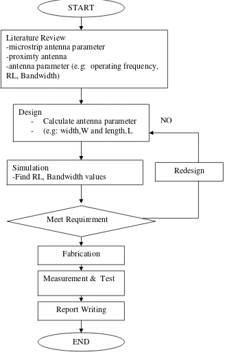
1.1 Project Methodology in a flowchart 4
2.1 Radiation Pattern for a Microstrip Antenna 9
2.2 Directivity of an Antenna 11
2.3 The Proximity-fed Rectangular Patch, MSA 14
2.4 Structure of a Microstrip Patch Antenna 15
2.5 Common Shapes of Microstrip Patch Elements 15
2.6 Microstrip Line Feed 18
2.7 Proximity-coupled Feed 19
2.8 Diagram of Proximity coupled antenna 20
2.9 Equivalent Circuit of a Proximity Coupled Antenna at the Patch Edge
20
2.10 Probe fed Rectangular Microstrip Patch Antenna 21
2.11 Aperture-Coupled Feed 22
2.12 Microstrip Line 24
2.13 Electric Field Lines 24
2.14 Microstrip Patch Antenna 25
2.15 Top View of Antenna 26
2.16 Side View of Antenna 26
3.1 Width and Length Calculation by using The TXLINE 29 3.2 Rectangular Inset Fed Designed at Frequency 2.4 GHz 30
3.3 Return Loss at -14.88 dB 31
3.4(a) Enclosure Set Up 32
xvi 3.4(c) Width and Length Calculation by using The TXLINE 32
3.4(d) 3D layout 33
3.5 Setting The Range of Frequencies 33
3.6 Setting The Graph Measurement 34
3.7 Wilkinson Power Divider 34
3.8 Example for 1 x 2 Microstrip Patch Antenna Array 35
3.9 Design Process for 1x2 Proximity Array 37
3.10 Design Process for 1x4 Proximity Array 40
3.11 Design Process for 2x4 Proximity Array 42
3.12 Fabrication Process 45
3.13 Fabrication Process 45
3.14 Antenna Measurement Tools 46
4.1 Layout of Inst Fed 48
4.2 EM Layout for Inset Fed 49
4.3 Impedance Locus for Inset Fed 49
4.4 Simulation Results for Inset Fed 50
4.5 Measurement Results for Inset Fed 52
4.6 Single Proximity 54
4.7 EM Layout for Layer 1 and Layer 2 55
4.8 Return Loss for Proximity at -19.3dB 55
4.9 Simulation Results for Single Proximity 56
4.10 Measurement Results for Single Proximity 56
4.11 Design of 1x2 Proximity Array Antenna 58
4.12 Return Loss for Proximity Array 1x2 at -22.16dB 58
4.13 Simulation Results for 1x2 Proximity Array 59
4.14 Simulation Results for 1x2 Proximity Array 59
4.15 Measurement Results for 1x2 Proximity Array 60
4.16 Design of 1x4 Proximity Array Antenna 61
4.17 Return Loss for 1x4 Proximity Array Antenna at -25.58dB 61 4.18 Measurement Results for 1x4 Proximity Array 63
xviii
LIST OF ABBREVIATIONS
w Width
h Dielectric Thickness
t Copper Thickness
L Length
Leff Effective Length of the Patch
fr Resonance Frequency
Yo Feed Line
Wavelength
εr Dielectric Constant
εo Permittivity of Free Space
o Permeability of Free Space
Zo Load Impedance
∆L Dimensions of the patch along its length
w/h Width-to-height ratio
a Radius
Inset Feed
Q Antenna Quality Factor
dB Decibel
dBi Decibel Isotropic
RL Return Loss
G Gain
Pr Radiated Power
Pi Input Power
Rin Real Part
xix
Cc Coupling Capacitance
S Distance
MPA Microstrip Patch Antenna
EM Electromagnetic
PCMA Proximity Coupled Microstrip Antenna
IEEE Institute of Electrical and Electronics Enginerring
WLAN Wireless Local Area Network
MW2004 Microwave Office 2004
FR4 Frame Resistance 4
ξ Tangent Loss
MMIC Monolithic Microwave Integrated Circuit
TEM Transverse Electric-Magnetic
TX line Transmission Line
UI User Interface
UV Ultra Violet
EM Electromagnetic
S11 Input Port 1 to Output Port 1
xx
LIST OF APPENDICES
APPENDIX DESCRIPTION PAGE
CHAPTER I
INTRODUCTION
1.1 Introduction
2 1.2 Scopes Of Work
This project consists of three major parts. The first scope of the project is to study the concept of proximity microstrip antenna for WLAN applications. The calculation of the parameter for rectangular patch antenna being studied. The simulation processed has been done by using microwave 2006. Then, the comparison between calculation and simulation were investigate. The calculation has been done at frequency 2.4 GHz. The array antenna are designed at 1x2, 1x4 and 2x4 configurations. The designed antenna are fabricated using the FR4 board with dielectric constant of 4.7. Finally, the characteristics of the antenna such as return loss, gain, bandwidth and radiation pattern were measured using appropriate equipments such network and spectrum analyzer.
1.3 Problem Statements
3 1.4 Project Objectives
4
Design
- Calculate antenna parameter - (e.g: width,W and length,L
Simulation
-Find RL, Bandwidth values Redesign
NO 1.5 Project Methodology
[image:24.612.220.548.163.675.2]There are four main methodology used in this project implementation. The methodology is as listed below:-
Figure 1.1: Project Methodology in a flowchart START
Meet Requirement
Fabrication
Report Writing Measurement & Test
END Literature Review
-microstrip antenna parameter -proximty antenna