TECHNICAL UNIVERSITY of MALAYSIA
MALACCA
Design and Development of Computer Program
to Determine 2D Robot Workspace and Safe
Working Area
Thesis submitted in accordance with the requirements of the Technical University of Malaysia, Melaka for the Bachelor Degree of Manufacturing
Engineering in Robotic and Automation
By
Nor Ismawati binti Natilan
UTeM Library (Pind.1/2005)
SULIT
TERHAD
TIDAK TERHAD
(Mengandungi maklumat yang berdarj ah keselamat an at au kepent ingan Malaysia yang t ermakt ub di dalam AKTA RAHSIA RASMI 1972)
(Mengandungi maklumat TERHAD yang t elah dit ent ukan oleh organisasi/ badan di mana penyelidikan dij alankan)
(TANDATANGAN PENULIS)
Alamat Tet ap:
No. 26, Jalan Kemuning 9,
Taman Kemuning, 42700 Bant ing, Selangor
* Tesis dimaksudkan sebagai t esis bagi Ij azah Dokt or Falsaf ah dan Sarj ana secara penyel idikan, at au disert asi bagi pengaj ian secara kerj a kursus dan penyel idikan, at au Laporan Proj ek Sarj ana Muda (PSM).
BORANG PENGESAHAN STATUS TESIS* UNIVERSITI TEKNIKAL MALAYSIA MELAKA
JUDUL: DESIGN AND DEVELOPMENT OF COMPUTER PROGRAM TO DETERMINE 2D ROBOT WORKSPACE AND SAFE WORKING AREA
SESI PENGAJIAN: 2/ 2006-2007
Saya _____________________________________________________________________
mengaku membenarkan t esis (PSM/ Sarj ana/ Dokt or Falsaf ah) ini disimpan di Perpust akaan Universit i Teknikal Malaysia Melaka (UTeM) dengan syarat -syarat kegunaan sepert i berikut :
1. Tesis adalah hak milik Universit i Teknikal Malaysia Melaka.
2. Perpust akaan Universit i Teknikal Malaysia Melaka dibenarkan membuat salinan unt uk t uj uan pengaj ian sahaj a.
3. Perpust akaan dibenarkan membuat salinan t esis ini sebagai bahan pert ukaran ant ara inst it usi pengaj ian t inggi.
4. **Sila t andakan (√)
NOR ISMAWATI BINTI NATILAN
DESIGN AND DEVELOPMENT OF COMPUTER PROGRAM
TO DETERMINE 2D ROBOT WORKSPACE AND SAFE
WORKING AREA
NOR ISMAWATI BINTI NATILAN
APPROVAL
This thesis submitted to the senate of UTeM and has been accepted as partial fulfillment of the requirement for the degree of Bachelor of Manufacturing Engineering
(Robotic and Automation). The members of the supervisory committee are as follows:
……… Main supervisor
Faculty of Manufacturing Engineering
DECLARATION
I hereby, declare this thesis entitled “ Design and Development of Computer Program to Determine 2D Robot Workspace and Safe Working Area" and submitted to Universiti Teknikal Malaysia, Melaka as fulfillment of the requirement for the degree of Bachelor
of Manufacturing Engineering .
ABSTRACT
Nowadays, industrial robots are widely used in manufacturing industries that is brought in a new challenge of safety aspects for workers and robots. Injury rates may increase without a proper safety system for industrial robot workspace. In addition, this project is design and develops with the purpose of decreasing the injury rates happened in the industries. The main objective of this project is to design and develop a computer program to determine 2D robot workspace and safe working area. In this project, the emphasis is safety and several aspects need to be considered during installation the industrial robot for ensure the safety in the future. The specific variables and dimensions are needed to be considered during installation the industrial robot and determine the robot work envelope.
ABSTRAK
Pada masa ini, robot industri telah digunakan secara meluas dalam industri pembuatan di mana ianya telah membawa cabaran atau impak baru dari segi aspek keselamatan untuk pekerja dan robot itu sendiri. Kadar kemalangan akan meningkat tanpa sistem keselamatan yang cukup untuk ruang kerja robot industri. Oleh itu, projek ini direka bertujuan untuk mengurangkan kadar kemalangan yang berlaku di dalam industri. Objektif utama projek ini adalah untuk merekabentuk dan memperkembangkan program komputer dalam menentukan ruang kerja robot dalam bentuk 2D dan kawasan kerja yang selamat. Dalam projek ini, keselamatan dan beberapa aspek yang perlu dipertimbangkan semasa memasang robot industri adalah amat dititikberatkan dalam menjamin keselamatan pada masa akan datang. Beberapa pembolehubah dan nilai-nilai ukuran yang tertentu adalah perlu dititikberatkan semasa memasang robot industri dan dalam menentukan ruang kerja robot industri itu sendiri.
DEDICATION
I dedicate this work:
To my caring father,
Tuan Natilan bin Samid
To my lovely mother,
Puan Mislinah binti Hj. Kassan
To my beloved brothers and sisters
To my supervisor,
En. Arfauz bin Abd Rahman
ACKNOWLEDGEMENTS
First and foremost, thanks to God because of His Willingness, I was complete my PSM report and had been representing this report titled ‘Design and Development of Computer Program to determine 2D Robot Workspace and Safe Working Area’ successfully. I also believe this report would not been completed and produced properly without the help from supervisor, lecturers, family and friends.
I would like to express my sincere grateful and appreciation to my supervisor, En. Arfauz bin Abd. Rahman for his support, intelligence in helping me to solve problems and share ideas related to my project, report revision and assessment.
I also would like to dedicate my gratefully acknowledge to all the FKP lecturer who had sharing ideas related to my project and giving useful guidance and some advice. Special thanks to my C++ lecturer from FTMK, En. Sanusi bin Azmi for his useful knowledge and ideas. All of their supports are greatly appreciated.
I also happy to present my gratefully acknowledge to my beloved family for their incessant love, support, continuous encouragement and understanding to made this project possible and success. Not forgetting special thanks to all friends for their support and understanding. They are always behind and with me along this project from start until end of this project.
TABLE OF CONTENTS
List of Abbreviations, Symbols, Specialized Nomenclature………..xii
1.0 GENERAL INTRODUCTION………...1
1.1 Introduction………1
1.2 Objectives of the project………4
1.3 Scopes of the project………...4
1.4 Layout of the thesis………5
2.0 LITERATURE REVIEW………6
2.1 Introduction………6
2.2 Robot and its Component………...8
2.2.1 Robot………...8
2.2.2 Robot Components………...…..…..11
2.2.2.1 Mechanical Unit………...11
2.2.2.2 Power Source………12
2.2.2.3 Control System………. …...12
2.2.2.4 Tooling………..13
2.3 Industrial Robot………...13
2.3.1 Classification of Industrial Robot………...14
2.3.1.1 Cartesian………....14
2.3.1.3 Spherical………....16
2.3.1.4 Articulated / Jointed Arm………...17
2.3.2 Brand of Industrial Robot………..18
2.3.2.1 ABB………...18
2.3.2.2 FANUC………...21
2.3.2.3 KAWASAKI………...23
2.3.2.4 MOTOMAN………...24
2.3.2.5 KUKA………27
2.3.3 Robot Working Envelope………...30
2.3.3.1 Example of Working Envelope for Articulated Arm Robot…….31
2.3.4 User Interface……….32
2.4 Computer Program Software……….33
2.4.1 Terms in OOP (Object Oriented Programming)………....33
2.4.2 Microsoft Visual Basic.NET………...34
2.4.2.1 Solving a Problem………...35
2.4.2.2 Planning an OOED Application………...36
2.4.2.3 Building a User Interface………...39
2.4.2.4 Coding an Application………...42
2.4.2.5 Testing, Debugging and Documenting………..42
2.4.3 Microsoft Visual C++.NET………...43
2.4.3.1 Structure of C++ Program………...46
2.4.3.2 Input, Processing, Output (IPO) Chart………..47
2.4.3.3 Coding the Algorithm into a Program………...49
2.4.3.4 Desk-Checking the Program………..49
2.4.3.5 Evaluating and Modifying the Program………50
2.5 Drawing Software………...51
2.5.1 AutoCAD………..51
2.5.2 Solidworks………52
3.0 METHODOLOGY………...55
3.1 Introduction………....55
3.2 Research Methodology………..58
3.3 Research Tool………...58
3.3.1 Books………..……...58
3.3.2 Thesis……….………58
3.3.3 Internet………...58
3.3.4 Journal………59
3.4 Research Planning………..59
3.4.1 PSM1 Gantt chart………...60
3.4.2 PSM2 Gantt chart………...61
4.0 DESIGN AND DEVELOPMENT………..62
4.1 Introduction………62
4.2 User Interface for This Project………...63
4.2.1 First Level User Interface………..65
4.2.2 Second Level User Interface………..66
4.2.3 Third Level or Result Level………...67
4.3 Coding for This Project………..69
4.3.1 Coding for First Level………69
4.3.2 Coding for Second Level……….………..70
4.3.2.1 Coding for BOIR1 (No. of Robot = 1)………..70
4.3.2.2 Coding for BOIR2 (No. of Robot = 2)………...71
4.3.2.3 Coding for BOIR3 (No. of Robot = 3)………..72
4.2.3.3 Coding for BOIR4 (No. of Robot = 4)………..73
4.3.3 Coding for Third Level or Result Level………74
4.3.3.1 Coding for FANUC Brand (No. of Robot = 1)………..74
4.3.3.2 Coding for FANUC Brand (No. of Robot = 2)………..77
4.3.3.3 Coding for FANUC Brand (No. of Robot = 3)………..78
4.3.3.5 Coding for ABB Brand (No. of Robot = 1)………..80
4.3.3.6 Coding for ABB Brand (No. of Robot = 2)………..83
4.3.3.7 Coding for ABB Brand (No. of Robot = 3)………..84
4.3.3.8 Coding for ABB Brand (No. of Robot = 4)………...85
4.3.3.9 Coding for KAWASAKI Brand (No. of Robot = 1)……….86
4.3.3.10 Coding for KAWASAKI Brand (No. of Robot = 2)…………...90
4.3.3.11 Coding for KAWASAKI Brand (No. of Robot = 3)…………...90
4.3.3.12 Coding for KAWASAKI Brand (No. of Robot = 4)………91
4.3.3.13 Coding for KUKA Brand (No. of Robot = 1)………..93
4.3.3.14 Coding for KUKA Brand (No. of Robot = 2)………..96
4.3.3.15 Coding for KUKA Brand (No. of Robot = 3)………..97
4.3.3.16 Coding for KUKA Brand (No. of Robot = 4)………..98
4.3.3.17 Coding for MOTOMAN Brand (No. of Robot = 1)………99
4.3.3.18 Coding for MOTOMAN Brand (No. of Robot = 2)…………..102
4.3.3.19 Coding for MOTOMAN Brand (No. of Robot = 3)…………..103
4.3.3.20 Coding for MOTOMAN Brand (No. of Robot = 4)…………..104
4.4 Conclusion………...105
5.0 DISCUSSION……….106
6.0 CONCLUSION AND RECOMMENDATION………...108
REFERENCES………...110
LIST OF FIGURES
2.2(f) Material Handling in the Semiconductor Industry 10
2.3 A Major Robot Components 11
2.4 A Cartesian Configuration 15
2.5 A Cylindrical Configuration 16
2.6 A Spherical Configuration 17
2.7 An Articulated / Jointed Arm Configuration 18
2.8 A Robot Work Envelope 31
2.9 Working Envelope for IRB1410 (Arc Pack) 32
2.10 Process the C++ Compiler 44
2.11 A Typical Program Development Environment 45
2.12 A Structure of C++ Program 46
2.13 IPO Chart with a Flowchart in the Processing Column 48
3.1 Research Methodology 56
3.2 Processes in Programming 57
4.1 First Level User Interface 65
4.2 Second Level User Interface show the List of Brand of Industrial Robot 66
LIST OF TABLES
1.1 Causes of Accidents in Robot Work Cells 3
2.1 Type of ABB Robot 19
2.2 Type of FANUC Robot 21
2.3 Type of KAWASAKI Robot 23
2.4 Type of YASKAWA Robot 26
2.5 Type of KUKA Robot 28
2.6 A Programmer Processes 37
2.7 An IPO Chart 47
LIST OF ABBREVIATIONS, SYMBOLS, SPECIALIZED
YEC - YASKAWA Electric Corporation OOP - Object-Oriented ProgrammingIDE - Integrated Development Environment OOED - Object-Oriented/Event-Driven
TOE - Task, Object, Event IPO - Input, Processing, Output CAD - Computer Aided Design
OLE - Object Linking and Embedding API - Application Programming Interface VBA - Visual Basic Appilication
CHAPTER 1
GENERAL INTRODUCTION
1.1 Introduction
There were about 750,000 robots working in industry worldwide. Modern industrial robot arms have increased in capability and performance through controller and language development, improved mechanisms, sensing and drive systems. In the early to mid 80's the robot industry grew very fast primarily due to large investments by the automotive industry. The robot industry has only recently recovered to mid-80's revenue levels [1].
Figure 1.1: Robotic Systems.
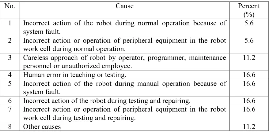
The statistics on occupational injuries compiled by Labor Department of Hong Kong in 1999, there were nearly 7000 injuries and 40 fatalities in manufacturing. These statistics also indicated that there were more than 1300 workers injured due to striking against or being struck by dynamic moving objects in the workplace [2]. In Sweden and Japan, some industrial accidents were related to robot operation including failure to stop, expected and unexpected pauses and starts of robot motion, high speed motion of the robot arm, entering the work envelope for troubleshooting repair and maintenance, unauthorized entry into general robot work envelope, intentional disabling of safety devices and robot work functions unknown to the operator [3]. There are eight causes for accidents in robot work cells identified in Japan as listed in Table 1.11[4, 5].
Table 1.1: Causes of Accident in Robot Work Cells
No. Cause Percent
(%) 1 Incorrect action of the robot during normal operation because of
system fault.
5.6 2 Incorrect action or operation of peripheral equipment in the robot
work cell during normal operation.
5.6 3 Careless approach of robot by operator, programmer, maintenance
personnel or unauthorized employee.
11.2
4 Human error in teaching or testing. 16.6
5 Incorrect action of the robot during manual operation because of system fault.
16.6 6 Incorrect action of the robot during testing and repairing. 16.6 7 Incorrect action or operation of peripheral equipment in the robot
work cell during testing and repairing.
16.6
8 Other causes 11.2
Virtual and real conditions can be compared. This software is expected can be used to help industry to establish realistic guidelines to improve facility design and reduce hazards in the workplace. The software could be used ultimately for risk reduction in the workplace.
1.2 Objectives of the project
The objectives of this project are as follow:
1. To create and determine 2D robot workspace and safe working area.
2. To evaluate current computer program to determine 2D robot workspace and safe working area.
3. To recommend for improvement of computer program to determine 2D robot workspace and safe working area.
4. To design and develop a new model of a computer program to determine 2D robot workspace and safe working area.
1.3 Scopes of the project
Scopes of this project include:
1. Collect necessary data on the current computer program to determine 2D robot workspace and safe working area.
2. Use any programming software and workspace software.
3. Create experimental documentation and user manual for Workspace software. 4. Design and develop a new model of a computer program and determine 2D robot
1.4 Layout of the thesis
The general introduction about this project is provides in Chapter 1 that discuss about the problem statement carried out for this project named “Design and Develop a computer program of 2D Robot Workspace and Safe Working Area”, objectives and scopes of this project briefly. Layout of this report is also presented in this chapter.
Chapter 2 provides a literature review or past studies in area relating to robot, industrial robot and work envelope for the robot in the industry, computer program and drawing software. This chapter is also as a reference to implement this project. List of brand and type of industrial robot is presented in this chapter that will be used and applied in this project. Computer program and drawing software will be choose and used to create, program and execute this project become success.
All of the method and analysis of the data used to implement this project is presented and described briefly in this chapter named Methodology chapter or Chapter 3. Flow chart of research methodology from start to end of this project is presented and explained briefly. Sources of the data and information are described in research tool. Project research planning for PSM1 and PSM2 that has been fixed in Gantt chart are outlined in this chapter.
The fourth chapter is Design and Development chapter. The emphasis of this chapter is the output of this project and it also including the analysis done during implements this project and presentation of the user interface.
CHAPTER 2
LITERATURE REVIEW
2.1 Introduction