SUPERVISOR DECLARATION
“I hereby declare that I have read this thesis and in my opinion this thesis is sufficient in term of scope and quality for the award of the degree of Bachelor of
Mechanical Engineering (Structure & Material).”
Signature : ………
Supervisor :DR. SITI HAJAR BINTI SHEIKH MD.FADZULLAH
THE EFFECT OF COUPLING AGENT ON THE MECHANICAL PROPERTIES OF PLA-BASED POLYMER COMPOSITES
NUR AMARINA BINTI MAHMOOD
This report is written as a partial fulfilment of terms in achieving the award for Bachelor of Mechanical Engineering (Structure & Material)(Hons.)
Faculty of Mechanical Engineering Universiti Teknikal Malaysia Melaka
ii
DECLARATION
“I hereby declare that the work in this thesis is my own except for summaries quotation which have been duly acknowledged”
iii
Thank you a lot to all of my family especially to my father and my mother for helping and support to finish this thesis.
iv
ACKNOWLEDGEMENT
Praise to Allah the Almighty, with His will I had finally completed preparing for this FYP thesis. I would like to take this opportunities to thank to my supervisor Dr Siti
Hajar Binti Sheikh Md Fadzullah for her never ending support, guidance, and advices during completion of this thesis.
My appreciation also goes to my parents for their support towards me to successfully done this project in order to graduate from UTeM. Last but not least, my appreciation
v
ABTRACT
vi
ABSTRAK
vii
TABLE OF CONTENT
CHAPTER TITLE PAGE
DECLARATION ii
DEDICATION iii
ACKNOWLEDGEMENT iv
ABSTRACT v
ABSTRAK vi
TABLE OF CONTENT vii
LIST OF TABLES x
LIST OF FIGURES xi
CHAPTER I INTRODUCTION 1
1.1 Background 1
1.2 Objectives 2
1.3 Scope of Research 3
1.4 Problem Statement 3
1.5 Planning And Execution 4
CHAPTER II LITERATURE REVIEW 6
2.1 Introduction to Composite Material 7 2.2 Polymer Matrix Composites 8
2.3 Biocomposites 10
viii
2.3.2 Matrix polymer matrix 12 2.3.3 Natural fibre reinforcement 13 2.4 Mechanical Properties if biocomposites 14
2.4.1 Tensile Properties of PALF reinforced PLA
composites 15
2.4.2 Flexural Properties of PALF reinforced PLA
composites 17
2.4.3 Impact properties 18
2.5 Chemical Treatment 20
2.5.1 Alkaline Treatment 20
2.5.2 Silane treatment 21
2.6 Summary 21
CHAPTER III METHODOLOGY 23
3.1 Introduction 23
3.2 Raw materials 25
3.2.1 Polylactid acid (PLA) 25
3.2.2 Pineapple leaf 26
3.3 Fabrication process 28
3.3.1 Preparation of PLAF 29 3.3.2 PALF-PLA Composite Preparation 30 3.3.3 Testing Sample Preparation 33
3.4 Testing Method 34
3.4.1 Tensile testing 34
3.4.2 Flexural testing 36
3.4.3 Impact Testing 38
ix
CHAPTER IV RESULTS AND DISCUSSION 42
4.1 Introduction 42
4.2 Tensile Properties 42
4.2.1 Failure mode on tensile sample 47
4.3 Flexural Properties 49
4.4 Impact Properties 52
4.4.1 Failure mode on impact testing 55
4.4 Morphological Study 56
CHAPTER V CONCLUSION AND RECOMMENDATION 60
5.1 Conclusion 60
5.2 Recommendation 61
x
LIST OF TABLES
NO TITLE PAGE
1.1 Gantt chart PSM I. 4
1.2 Gantt chart PSM II. 5
2.1 Advantages and disadvantages of composites. 8 2.2 Advantage and disadvantage of thermosets and 9
thermoplastic
2.3 Properties of PLA and PLAF 15
2.4 Average value of flexural strength and modulus of elastic 21 3.1 PLA Ingeo Biopolymer 6100D Technical Data Sheet 26 4.1 The results of tensile testing properties obtained from 44
the tensile test on the PLA sample.
4.2 The results of tensile properties from tensile test on 44 the composites samples.
4.3 Comparison data between experimental value, theoretical 45 and references.
4.4 Observation the failure mode of Plain PLA. 48 4.5 Observation the failure mode of composites. 49 4.6 The results of flexural properties obtained from flexural 50
test on pure PLA samples.
4.7 The results of flexural testing obtained on composites 50 samples.
xi
NO TITLE PAGE
4.10 The results of tensile testing obtained on composites 53 samples.
4.11 Comparison data between experimental value and 53 literature review.
4.12 Observation the failure mode of Pure PLA. 55 4.13 Observation the failure mode of composites. 56 5.1 Summary of main findings from the experimental 61
xii
LIST OF FIGURES
NO TITLE PAGE
2.1 Development of Biocomposites from Renewable Resource 10 2.2 Development process and value chain of biocomposites industry in
Malaysia 12
2.3 Polylactic acid (PLA) polymerization 12
2.4 Categories of Natural Fibres 14
2.5 Tensile properties of PLAF/PLA composites showing tensile
strength and tensile modulus 16
2.6 Elongation at break of PALF/PLA composites 16 2.7 Flexural properties of 40 wt% surface-treated PALF fibbers
compared to untreated PALF fibres reinforced composites 17 2.8 Stress–strain curves: (a) neat PLA (b) PLA/PALF (60/40), (c)
PLA/PALFNA(60 wt%/40 wt%) , (d) PLA/PALFSI (60 wt%/40
wt%) and (e) PLA/PALFNASI 18
2.9 Notched Izod impact strength of 40 wt% surface-treated PALF fibres compared to untreated PALF fibres reinforced composites 19 2.10 Dependence of impact strength on the content for PLA/PALF
composites: (i) PLA/PALF, (ii) PLA/PALFNA (iii) PLA/PALFSI
xiii
3.1 Flow chart of the project research 24
3.2 PLA pellet 25
3.3 Pineapple leaf as natural fibre 27
3.4 Fabrication process of the PALF reinforced PLA composites 28 3.5 PLAF immersed in 5% concentration of NaOH 29
3.6 PLAF was dried 30
3.7 Graph of temperature vs Time for hot press machine during
fabrication process. 31
3.8 Mould dimension 180mm x 180mm 31
3.9 Hot Isostatic Press Machine 32
3.10 Composite Plate 32
3.11 Shearing machine to cut sample inti size 33 3.12 Detail dimension on tensile specimen 34 3.13 Universal Testing Machine for Tensile and Flexural Testing 35 3.14 (a) Pure PLA test that have been failed (b) Composites that have
been failed 36
3.15 Allowable Range of Loading Nose and Support Radii in ASTM
D790 37
3.16 Charpy impact tester 40
3.17 Dimension of the charpy impact test 40
3.18 Mini sputter Coater machine 40
3.19 The samples that have been coated 41
3.20 Scanning Electron Microscope (SEM) 41
xiv
4.3 Graph of tensile strength versus type of samples 45 4.4 Graph of Young’s modulus versus type of samples 46 4.5 Graph of comparison on the tensile strength for composites treated
with NaOH, treated with silane coupling agent and theoretical 46 4.6 Graph of comparison on Young’s Modulus for composites treated
with NaOH and theoretical. 47
4.7 Graph of Flexural strength versus type of samples 51 4.8 Graph of flexural modulus versus type of samples 51 4.9 Graph of comparison on the flexural strength for composites treated
with NaOH and treated with silane coupling agent 51 4.10 Graph of comparison on the flexural modulus for composites treated
with NaOH and treated with silane coupling agent 52 4.11 Graph of energy absorbed versus type of sample 54 4.12 Graph of comparison on the energy absorbed for composites
1
CHAPTER I
INTRODUCTION
1.1 BACKGROUND
The growing environmental awareness, the concern for environmental sustainability and the growing wasted problem is increased year by year. The production of fuel-derived plastics is often harmful to the environment [1]. For example automotive applications based on natural fibres with polypropylene as matrix material are very common today [2]. Limited studies have been carried out on composites with matrices, which originate from renewable raw materials. There are many different polymers of renewable material. For example, polylactic acid, cellulose esters, poly hydroxyl butyrates, starch and lignin based plastics, are some of the renewable polymer materials or biopolymer [3].
2
However, the processes involved in using natural plant fibres as a reinforcement are different from those using industrial products such as glass and carbon fibres. The shape, size, and strength of the natural plant fibres may vary widely depending on cultivation environment, region of origin, and other characteristics. Besides, these features of the natural fibres are likely to influence the mechanical properties of the natural fibre-reinforced plastics [4].
Coupling agents are used to provide a stable bond between two otherwise non-bonding and incompatible surfaces. In reinforced and filled plastics, the improved bond between the fibrous or particulate inorganic component and the organic matrix polymer results in greater composite strength [5]. Coupling agent are commonly employed to treat fibre surfaces in order to improve interfacial adhesion within composites which can also in some cases improve their initial mechanical properties. Coupling agent investigated include, but are not limited to; conventional silanes, various phosphonic acids, poly-(HEMA), zirconate and titanate coupling agents [6].
1.2 OBJECTIVES
The objectives of this research are listed as below:
i. To develop PLA-based polymer composites using pineapple leaf fibre as reinforcement.
ii. To study the effect of using chemical coupling agent on the bonding mechanism present.
3
1.3 SCOPE OF RESEACRH
The scopes of this research are listed as below:
i. selection of materials and coupling agent for the composites. ii. fabrication of biodegradable polymer composites test panels. iii. mechanical testing.
iv. physical testing. v. surface morphology.
1.4 PROBLEM STATEMENT
The developing environmental awareness and new rules and regulations are forcing the industries to seek more ecologically friendly materials for their products [3]. There are many different polymers are renewable materials for example polylactic acid, starch, cellulose esters and lignin based plastics. The problems with these polymers have been poor commercial availability, poor processability, low toughness, high price and low moisture stability.
4
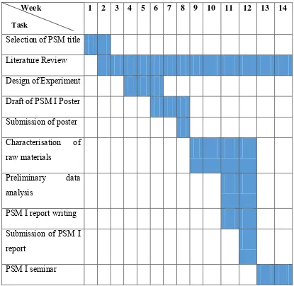
[image:19.595.111.526.182.586.2]1.5 PLANNING AND EXECUTION
Table 1.1: Gantt chart PSM I
Week 1 2 3 4 5 6 7 8 9 10 11 12 13 14
Selection of PSM title Literature Review Design of Experiment Draft of PSM I Poster Submission of poster Characterisation of raw materials
Preliminary data analysis
PSM I report writing Submission of PSM I report
5
[image:20.595.112.563.306.673.2]The Gantt chart shows project the planning for Final Year Project ( PSM I) which commences in September 2014. The research activities include selection of research title and approval by the respective lecturer, literature review that is continuous throughout the studies, design of experiment, as well as establishing the methodology. This is followed by poster preparation and submission. After that fabrication process. Once required results and analysis, report PSM I will be submitted and have PSM I seminar.
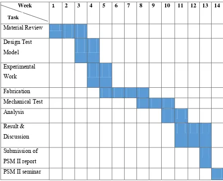
Table 1.2: Gantt chart PSM II
Week 1 2 3 4 5 6 7 8 9 10 11 12 13 14
Material Review Design Test Model Experimental Work
Fabrication Mechanical Test Analysis
Result & Discussion Submission of PSM II report PSM II seminar
6
CHAPTER II
LITERATURE REVIEW
2.1 INTRODUCTION TO COMPOSITE MATERIAL
7
Nature also has its own composites in the form of wood, teeth, bones, muscle tissue, etc. In general the composite materials consist of a matrix reinforced with fibres. The biggest advantage of modern composite materials is that they are light as well as strong. By choosing an appropriate combination of matrix and reinforcement material, a new material can be made that exactly meets the requirements of a particular application. Composites also provide design flexibility because many of them can be moulded into complex shapes. The downside is often the cost. Although the resulting product is more efficient, the raw materials are often expensive [11].
High performance fibre reinforced composite materials are comprised of high strength and modulus fibres, embedded in, or bonded to, a matrix, with a distinct interface between them. In a composite, the fibre, as well as the matrix, retain their physical and chemical identities, but still provide a combination of properties that cannot be achieved with either of the constituents alone. In general the fibres play the role of load bearer. The matrix, while keeping the fibres in the desired location and orientation, act as a load transfer agent and protects the fibres from external conditions such as chemicals, heat and moisture [12].
8
Table 2.1: Advantages and disadvantages of composites [11].
Advantages Disadvantages
Weight reduction Cost of raw materials and fabrication
High strength or stiffness to weight ratio
Transverse properties may be weak
Tailorable properties: can tailor strength or stiffness to be in the load direction
Matrix weakness, low toughness
Redundant load paths (fibre to fibre) Matrix subject to environmental degradation
Longer life (no corrosion), better fatigue life
Difficult to attach
Lower manufacturing costs Non-destructive testing tedious
2.2 POLYMER MATRIX COMPOSITES
9
Thermoset have cross-linked or network structures with covalent bonds with all molecules. They do not soften but decompose on heating. Once solidified by cross-linking process they cannot be reshaped. Common examples are epoxies, polyesters, phenolics, ureas, melamine, silicone, and polyimides [14].
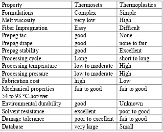
[image:24.595.154.487.378.647.2]The difference between thermoplastics and thermosets plastics is that thermoplastics become soft, remoldable and weldable when heat is added. Thermoets plastics however cannot be welded or remolded when heated, simply burning instead. On the other hand, once a thermosets is cured it tends to be stronger than a thermoplastic [14].
Table 2.2: Advantages and disadvantage of thermosets and thermoplastics [14].
Property Thermosets Thermoplastics
Formulations Complex Simple
Melt viscosity very low High Fiber Impregnation Easy Difficult
Prepeg tac good None
Prepag drape good none to fair
Prepag stability good Excellent Processing cycle Long short to long Processing temperature low to moderate High
Processing pressure low to moderate High
Fabrication cost high Low
Mechanical properties fair to good fair to good
54 to 93 °C.hot/wer
Environmental durability good Unknown Solvent resistance excellent poor to good Damage tolerance poor to excellent fair to good
![Table 2.1: Advantages and disadvantages of composites [11].](https://thumb-ap.123doks.com/thumbv2/123dok/498107.55695/23.595.115.570.98.431/table-advantages-disadvantages-composites.webp)