UNIVERSITI TEKNIKAL MALAYSIA MELAKA
DEVELOPMENT OF ALTERNATIVE POWER SUPPLY TO
CHARGE SMALL GADGETS
This report is submitted in accordance with requirement of the Universiti Teknikal Malaysia Melaka (UTeM) for the Bachelor of Electronics Engineering Technology
(Industrial Electronics) with Honours
by
MUHAMAD FAIZ BIN CHE PA @ MUSTAPA B071210300
900131-03-5339
UNIVERSITI TEKNIKAL MALAYSIA MELAKA
BORANG PENGESAHAN STATUS LAPORAN PROJEK SARJANA MUDA
TAJUK: DEVELOPMENT OF ALTERNATIVE POWER SUPPLY TO CHARGE SMALL GADGETS
SESI PENGAJIAN: 2014/15 Semester 2
Saya MUHAMAD FAIZ BIN CHE PA @ MUSTAPA
mengaku membenarkan Laporan PSM ini disimpan di Perpustakaan Universiti Teknikal Malaysia Melaka (UTeM) dengan syarat-syarat kegunaan seperti berikut:
1. Laporan PSM adalah hak milik Universiti Teknikal Malaysia Melaka dan penulis. 2. Perpustakaan Universiti Teknikal Malaysia Melaka dibenarkan membuat salinan
untuk tujuan pengajian sahaja dengan izin penulis.
3. Perpustakaan dibenarkan membuat salinan laporan PSM ini sebagai bahan pertukaran antara institusi pengajian tinggi.
SULIT
TERHAD
TIDAK TERHAD
(Mengandungi maklumat yang berdarjah keselamatan atau kepentingan Malaysia sebagaimana yang termaktub dalam AKTA RAHSIA RASMI 1972)
(Mengandungi maklumat TERHAD yang telah ditentukan oleh organisasi/badan di mana penyelidikan dijalankan)
_____________________
Alamat Tetap:
Lot 310 Jln Masjid Salor,
15100 Kota Bharu,
Kelantan.
Disahkan oleh:
_____________________
Cop Rasmi:
i
DECLARATION
I hereby, declare this report entitled “Development of Alternative Power Supply to Charge Small Gadgets” is the results of my own research except as cited in
references.
Signature : ………...
Author’s Name : MUHAMAD FAIZ BIN CHE PA @ MUSTAPA
ii
APPROVAL
This report is submitted to the Faculty of Engineering Technology of UTeM as a partial fulfillment of the requirements for the degree of Bachelor of Electronics Engineering Technology (Industrial Electronics) with Honours. The member of the supervisory is as follow:
Signature : ……….
Supervisor’s Name : SITI HALMA BINTI JOHARI
iii
ABSTRACT
iv
ABSTRAK
v
DEDICATION
I would like to dedicate this thesis to my beloved mother, Fatimah Bt Abu Bakar and my family members. There is no doubt in my mind that without their continued
vi
ACKNOWLEDGEMENT
vii
LIST OF ABBREVIATIONS, SYMBOLS AND NOMENCLATURE ... xi
CHAPTER 1 ... 1
viii
2.6 Thermoelectric Generator Modeling ... 12
2.7 Heat Flow Layout ... 14
2.8 Boost Converter ... 15
CHAPTER 3 ... 18
Methodology ... 18
3.1 Introduction ... 18
3.2 Overview of Flow chart ... 18
3.3 Flow of the Project ... 19
CHAPTER 4 ... 21
RESULTS AND ANALYSIS ... 21
4.1 Introduction ... 21
4.2 Simulation and Hardware ... 21
ix
LIST OF TABLES
Table 2. 1: Seebeck coefficients for some metal and alloys, compared to
platinum(Lasance, 2006) ... 7
Table 2. 2: Seebeck Coefficients for Standard Thermocouple(Lasance, 2006) ... 8
Table 2. 3: Seebeck coefficients for some semiconductors(Lasance, 2006) ... 9
Table 2. 4 : TEG1-199-104-0.5 module Specification ... 13
Table 4. 1 : TEG Module Output ... 24
Table 4. 2 : Boost Converter Output ... 28
Table 4. 3 : TEG Output Power (Input) ... 32
Table 4. 4 : Boost Converter Output Power (Output) ... 33
Table 4. 5 : Efficiency Table ... 34
x
LIST OF FIGURES
Figure 2. 1 : Thermoelectric Power Generation Concept... 4
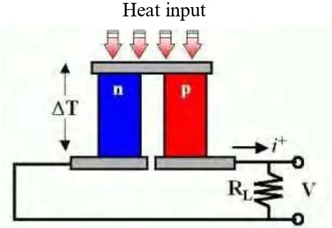
Figure 2. 2 : Seebeck Effect Concept ... 5
Figure 2. 3 : Thermoelectric Power Generation Concept... 10
Figure 2. 4 : Thermoelectric Generator Module ... 11
Figure 2. 5 : TEG Construction ... 11
Figure 2. 6 : Arrangement of Thermoelement in TEG Module ... 12
Figure 2. 7: Heat Flow... 14
Figure 2. 8 : Boost Converter ... 15
Figure 2. 9 : When Switched is closed ... 15
Figure 2. 11 : When Switch is opened ... 16
Figure 3. 1: Flow Chart of this Project ... 20
Figure 4. 1 : Temperature & Voltage Controller Circuit... 22
Figure 4. 2 : Hardware Connection During Testing ... 22
Figure 4. 3 : Charging Process ... 23
Figure 4. 4 : Heating Process ... 23
Figure 4. 5 : TEG Module Output (Current Vs Time) ... 25
Figure 4. 6 : TEG Module Output (Voltage Vs Time) ... 25
Figure 4. 7 : TEG Module Output (Current Vs Temperature) ... 26
Figure 4. 8 : TEG Module Output (Voltage Vs Temperature) ... 27
Figure 4. 9 : Boost Converter Output (Current Vs Time) ... 29
Figure 4. 10 : Boost Converter Output (Voltage Vs Time) ... 30
Figure 4. 11 : Boost Converter Output (Current Vs Temperature) ... 31
xi
LIST OF ABBREVIATIONS, SYMBOLS AND
NOMENCLATURE
TEG - Thermoelectric Generator
VS - Source Voltage
VO - Output Voltage
VL - Inductor Voltage IL - Inductor Current
1
CHAPTER 1
Introduction
This chapter will provide an overview about this project. It is divided into multiple sub-sections which is project background, problem statement, project objectives and scope.
1.2 Project Background
In present times, small electronic gadgets such as smartphone, camera, GPS device and others has become a norm nowadays. But one of the limitations of these gadgets is a power reserve. The battery of these gadgets can’t stand for a long time when it was used extensively. Example like, smartphone nowadays can only stand an averagely for one day and a half before it dies. So, this has become a major problem for a people that always went for a camping trip, hiking or backpacking because usually these people went for places that didn’t have an on-grid power supply to charging back their gadgets.
2 1.2 Problem Statement
This project will be implemented to overcome several problems that arising which is: Needs of an alternative power source to charge small electronic gadgets while
went for a camping trip, hiking or backpacking for a several days.
Problem of needs of an off grid power source to charge an important electronic gadgets like smartphone and etc. when a disaster happen. Example like flood, earthquake and others.
Need of a power supply when the main power source fails.
1.3 Project Objectives
The objective of this project is:
To study whether heat energy can be a reliable power source.
To develop an alternative power supply when the main power source can’t be reach or fails.
To analyze the electricity generated by thermal energy.
1.4 Scope
3
CHAPTER 2
Literature Review
2.1 Introduction
This chapter will provide an overview of what research that has been done in completing this project. In completing this project, there are several research that has been done to collect a suffice data that needed to develop this small power generator. The content of the research consist of thermoelectricity, Peltier and Seebeck effect and other important materials needed.
2.2 Thermoelectric
4
Figure 2. 1 : Thermoelectric Power Generation Concept
Thermoelectricity can be used for electric power generation (Seebeck effect) or for heating/cooling applications (Peltier effect). Electric power generation has not only been very successful for specialized applications such as satellites, but also to generate electricity at remote places using gas heaters and to make use of wasted-heat sources at low temperature. Cooling applications have only succeeded in low power applications such as camping coolers and small (hotel) refrigerators. For higher thermal power other cooling technologies overcome thermoelectricity by attaining better performance and lower prices.
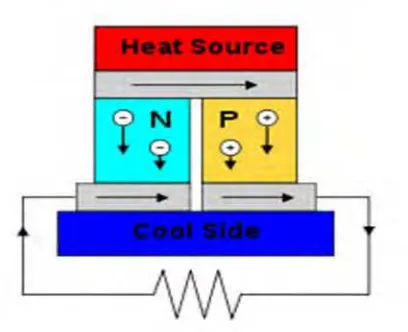
2.3 Peltier Effect
Peltier effect is the existence of cooling or heating at a junction of two different conductors. This effect is named after French physicist Jean Charles Athanase Peltier who discovered this effect in 1834(Effects, 2003). Peltier Effect is the reverse of Seebeck Effect. This term is used to develop a cooler for microelectronic devices like microcontrollers and computer CPU. Although Peltier cooler is not very efficient as some other types of cooler, they are accurate, easy to control and easy to adjust.
5 2.4 Seebeck Effect
Seebeck Effect is first discovered by German Physicist Thomas Johann Seebeck in 1821. In his observation, Seebeck reported for the first time on his observation that a magnetic compass needle is deflected when the junctions in a closed loop of two dissimilar metals or semiconductors are at different temperatures, at a session of the Berlin Academy of Sciences on December 14, 1820(Velmre, 2007). This due to a metal responded to temperature difference in a different ways thus creating current loop and magnetic field. He called it “Thermomagnetism”. Danish Physicist, Hans Christian Ørsted detects the mistake and change the term to “Thermoelectricity” due to electrical current involved. The temperature difference produces a voltage that can drive an electric current in a closed circuit afterward.
Figure 2.2 shows a thermoelectric that is composed of materials of different Seebeck coefficient (p-doped and n-doped semiconductors), configured as a thermoelectric generator. If the load resistor at the bottom is replaced with a Voltmeter, the circuit then functions as a temperature-sensing thermocouple.
6
The voltage produced is proportional with temperature difference between the junctions. This is proved by the equation 2.1 below.
V = ɑ (Th – Tc) (2. 1)
V = Voltage difference a = Seebeck coefficient
Th = Temperature at hot junction Tc = Temperature at cold junction
Seebeck Coefficient:
V = ɑ (Th – Tc) (2. 2)
Seebeck Coefficient =
7
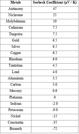
Table 2. 1: Seebeck coefficients for some metal and alloys, compared to platinum(Lasance, 2006)
Metals Seebeck Coefficient (µV / K)
8
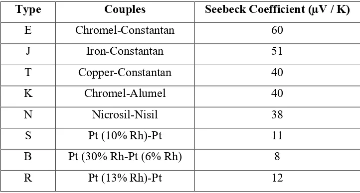
Table 2. 2: Seebeck Coefficients for Standard Thermocouple(Lasance, 2006)
Type Couples Seebeck Coefficient (µV / K)
E Chromel-Constantan 60
J Iron-Constantan 51
T Copper-Constantan 40
K Chromel-Alumel 40
N Nicrosil-Nisil 38
S Pt (10% Rh)-Pt 11
B Pt (30% Rh-Pt (6% Rh) 8
9
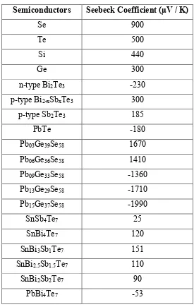
Table 2. 3: Seebeck coefficients for some semiconductors(Lasance, 2006)
Semiconductors Seebeck Coefficient (µV / K)
10
2.5 Thermoelectric Generator (TEG) Module
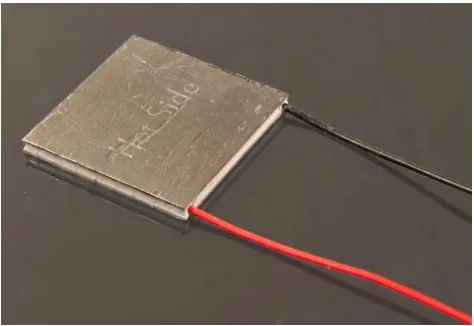
Solid state thermoelectric generators (TEGs) are devices that can convert thermal gradients to electrical power through the Seebeck effect(Annapragada, Salamon, Kolodner, Hodes, & Garimella, 2012). These devices are reliable, low noise and low cost, but suffer from low conversion efficiencies (Min & Rowe, 2002). Thermal energy is an energy that is wasted in the form of heat for a vast variety of everyday situations ranging from exhaust pipes in cars, to heat generated on a microprocessor to even heat generated by the human body. Any device that can transform that heat into electrical power could potentially be very useful, provided that the obtained power is sufficient for practical applications. But some changes need to be made to improve the output power of any thermoelectric generator. Figure 2.4 shows a real TEG module which has two sides, cool side and a hot side.
Figure 2. 3 : Thermoelectric Power Generation Concept
11
Figure 2. 4 : Thermoelectric Generator Module
Figure 2.5 shows a construction of TEG module. this TEG module consist of n-type semiconductor and p-type semiconductor. Other than semiconductor, TEG module also consist of metal conductors and ceramic insulator. Nowadays, TEG module are made from a highly doped semiconductors consisting of Bismuth Telluride(Bi2Te3), Lead Telluride(PbTe), Calcium Manganese Oxide(CMO) or a combination of all those. These depends on the temperature.