Abstract—In this paper, we present the doubly-fed induction generator (DFIG) control in wind energy conversion system using adaptive neuro-fuzzy approach. The wind turbine driven by doubly-fed induction machine is a part of distributed generation which feeds ac power to the distribution network. The system is modeled and simulated in the Matlab Simulink environment in such a way that it can be suited for modeling of all types of induction generator configurations. The model makes use of rotor reference frame using dynamic vector approach for machine model. Adaptive neuro-fuzzy controller is applied to rotor side converter for active power control and voltage regulation of wind turbine. Wind turbine and its control unit are described in details. All power system components and the adaptive neuro-fuzzy controller are simulated in Matlab Simulink software. For studying the performance of controller, different abnormal conditions are applied even the worst case. Simulation results prove the excellent performance of adaptive neuro-fuzzy control unit as improving power quality and stability of wind turbine.
Index Terms—Distributed Generation, Doubly-Fed Induction Machine, Wind Energy Conversion Systems, ANFIS.
I. INTRODUCTION
ind energy is the fastest growing and most promising renewable energy source among them due to economically viable [1-3]. Many applications of wind power can be found in a wide power range from a few kilowatts to several megawatts in small scale off-grid standalone systems or large scale grid-connected wind farms. Recently Enercon constructed a wind turbine of 4.5 MW with rotor diameter of 112.8 meters. Due to lack of control on active and reactive power, this type of distributed power generation causes problems in the electrical connected system. So this requires accurate modeling, control and selection of appropriate wind energy conversion system.
During last two decades, the high penetration of wind turbines in the power system has been closely related to the advancement of the wind turbine technology and the way of how to control. Doubly-fed induction machines are receiving increasing attention for wind energy conversion system during such situation. because the main advantage of such machines is that, if the rotor current is governed applying field orientation control-carried out using commercial double sided PWM inverters, decoupled control of stator side active and reactive power results and the power processed by the power converter is only a small fraction of the total system power. So, doubly-fed induction machine with vector control is
very attractive to the high performance variable speed drive and generating applications [4-5]. With increasing penetration of wind-derived power in interconnected power systems, it has become necessary to model the complete wind energy systems in order to study their impact and also to study wind power plant control.
Doubly fed induction generator (DFIG) is one of the most popular wind turbines which includes an induction generator with slip ring, a partial scale power electronic converter and a common DC-link capacitor. Power electronic converter which encompasses a back to back AC-DC-AC voltage source converter has two main parts; grid side converter (GSC) that rectifies grid voltage and rotor side converter (RSC) which feeds rotor circuit. Power converter only processes slip power therefore it’s designed in partial scale and just about 30% of generator rated power [6] which makes it attractive from economical point of view. Many different structure and control algorithm can be used for control of power converter. One of the most common control techniques is decouple PI control of output active and reactive power to improve dynamic behavior of wind turbine. But due to uncertainty about the exact model and behavior of some parameters such as wind, wind turbine, etc., and also parameters values differences during operation because of temperature, events or unpredictable wind speed, tuning of PI parameters is one of the main problems in this control method.
Control of Doubly-Fed Induction Generator in Distributed
Generation Units Using Adaptive Neuro-Fuzzy Approach
RAMADONI SYAHPUTRA1,2,IMAM ROBANDI1,MOCHAMAD ASHARI1
1Department of Electrical Engineering
Faculty of Industrial Technology, Institut Teknologi Sepuluh Nopember, Surabaya, Indonesia
2
Department of Electrical Engineering
Faculty of Engineering, Universitas Muhammadiyah Yogyakarta, Yogyakarta, 55183, Indonesia Email: ramadoni11@ mhs.ee.its.ac.id, [email protected], [email protected]
This paper investigates dynamic modeling of a variable speed DFIG wind turbine using adaptive neuro-fuzzy controller in Matlab Simulink software. Different parameters in normal and abnormal conditions based on adaptive neuro-fuzzy control are studied. A main grid with a 9MW DFIG wind turbine is used and focuses turned to fuzzy control unit and its effects on the power quality and system response of operation using MATLAB Simulink environment.
II. FUNDAMENTAL THEORY
A. Distributed Generation
Distributed generations (DGs) sometimes provide the most economical solution to load growth. Low voltages or overloads that are created by load growth may only exist on a circuit for a small number of hours per year. There are many locations within the troubled circuit, or even in neighboring circuits, where a DG may be located to provide control needed to eliminate the low voltage or overload. We assume that it has already been justified that a DG provides the lowest cost solution to a circuit problem and is to be installed to provide the needed control. Placing DGs further out on the circuit can lead to improvements in losses, reliability, or both.
B. Wind Energy Conversion System
There were several attempts to build large scale wind powered system to generate electrical energy. The first production of electrical energy with wind power was done in 1887 by Charles brush in Cleveland, Ohio. DC generator was used for power production and was designed to charge the batteries. The induction machine was used at the first time in 1951.
Wind turbines convert the kinetic energy present in the wind into mechanical energy by means of producing torque. Since the energy contained by the wind is in the form of kinetic energy, its magnitude depends on the air density and the wind velocity. The wind power developed by the turbine is given by the equation (1) [7]:
(1)
where Cp is the Power Co-efficient, ρ is the air density in kg/m3, A is the area of the turbine blades in m2 and V
is the wind velocity in m/sec. The power coefficient Cp gives the fraction of the kinetic energy that is converted into mechanical energy by the wind turbine. It is a function of the tip speed ratio λ and depends on the blade pitch angle for pitch-controlled turbines. The tip speed ratio may be defined as the ratio of turbine blade linear speed and the wind speed
(2)
Substituting (2) in (1), we have:
(3)
The output torque of the wind turbine Tturbine is calculated by the following equation (4):
(4) where R is the radius of the wind turbine rotor (m) There is a value of the tip speed ratio at which the power coefficient is maximum. Variable speed turbines can be made to capture this maximum energy in the wind by operating them at a blade speed that gives the optimum tip speed ratio. This may be done by changing the speed of the turbine in proportion to the change in wind speed. Fig.1 shows how variable speed operation will allow a wind turbine to capture more energy from the wind [8]. As one can see, the maximum power follows a cubic relationship. For variable speed generation, an induction generator is considered attractive due to its flexible rotor speed characteristic in contrast to the constant speed characteristic of synchronous generator.
Fig.1. Wind turbine characteristics [8].
In this study, the rotor is running at subsynchronous speed for wind speeds lower than 10 m/s and it is running at a super-synchronous speed for higher wind speeds. The turbine mechanical power as function of turbine speed is displayed in for wind speeds ranging from 5 m/s to 16.2 m/s.
C. Doubly-Fed Induction Machine
This is mainly due to the defined relationship between the export of P and absorption of Q. However, induction generators have the benefits of providing large damping torque in the prime mover, which makes it suitable for the application in fixed speed wind turbines. The fixed speed wind turbine uses a squirrel cage induction generator that is coupled to the power system through a connecting transformer. Due to different operating speeds of the wind turbine rotor and generator, a gearbox is used to match these speeds. The generator slip slightly varies with the amount of generated power and is therefore not entirely constant.
General concept of the doubly-fed induction machine is shown in Fig.2. [8]. The mechanical power generated by the wind turbine is transformed into electrical power by an induction generator and is fed into the main grid through the stator and the rotor windings. The rotor winding is connected to the main grid by self-commutated AC/DC converters allowing controlling the slip ring voltage of the induction machine in magnitude and phase angle [10]. In contrast to a conventional, singly-fed induction generator, the electrical power of a doubly-fed induction machine is independent from the speed. Therefore, it is possible to realize a variable speed wind generator allowing adjusting the mechanical speed to the wind speed and hence operating the turbine at the aerodynamically optimal point for a certain wind speed range.
Fig.2. Typical of doubly-fed induction machine [8].
Half of the world’s leading wind turbine manufacturers use the doubly fed induction generator systems [11]. This is due to the fact that the power electronic converter only has to handle a fraction (20% – 30%) of the total power, i.e., the slip power. This means that if the speed is in the range ±30% around the synchronous speed, the converter has a rating of 30% of the rated turbine power, reducing the losses in the power electronic converter, compared to a system where the converter has to handle the total power. In addition, the cost of the converter becomes lower. The doubly fed induction machine has been used in wind turbines for a long time. In the past, the ACAC converter connected to the rotor consisted of a rectifier
and inverter based on thyristor bridges. Nowadays, AC-AC converters are equipped with bidirectional IGBT's, connecting the rotor of the variable speed doubly fed induction generator to the electrical grid.
III. ADAPTIVE NEURO-FUZZY METHOD
of least squares estimation and back propagation for membership function parameter estimation.
The suggested ANFIS has several properties: 1. The output is zeroth order Sugeno-type system. 2. It has a single output, obtained using weighted
average defuzzification. All output membership functions are constant.
3. It has no rule sharing. Different rules do not share the same output membership function, namely the number of output membership functions must be equal to the number of rules.
4. It has unity weight for each rule.
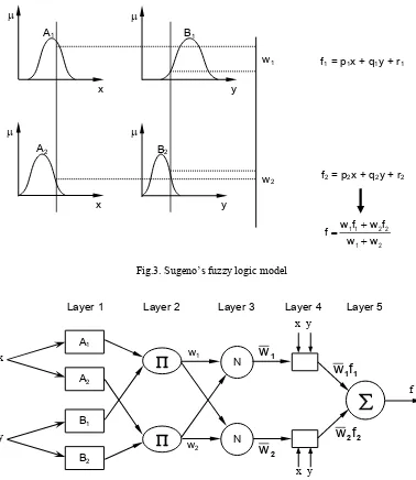
Fig.3 shows Sugeno’s fuzzy logic model, while Fig.4 shows the architecture of the ANFIS, comprising by input, fuzzification, inference and defuzzification
layers. The network can be visualized as consisting of inputs, with N neurons in the input layer and F input membership functions for each input, with F*N neurons in the fuzzification layer. There are FN rules with FN neurons in the inference and defuzzification layers and one neuron in the output layer. For simplicity, it is assumed that the fuzzy inference system under consideration has two inputs x and y and one output z as shown in Fig. 2. For a zero-order Sugeno fuzzy model, a common rule set with two fuzzy if-then rules is the following:
Rule 1: If x is A1 and y is B1, Then f1 = r1 (5)
Rule 2: If x is A2 and y is B2, Then f2 = r2 (6)
Fig.3. Sugeno’s fuzzy logic model
Fig.4. The architecture of the ANFIS with two inputs and one output.
A1
A2
B1
B2
A1
A2
B1x
B2
y
x
N x
N y
yf
w1
x y
w2
x y
f1 = p1x + q1y + r1
2
w
f2 = p2x + q2y + r2
1
w
2 1
2 2 1 1
w w
f w f w f
w1
w2
1 1
f
w
2 2
f
w
Here the output of the ith node in layer n is denoted as On,i:
Layer 1. Every node i in this layer is a square node with a node function:
1 i
O
= Ai(x), for i = 1, 2, (7)or,
1 i
O
= Bi-2(y), for i = 3, 4 (8)where x is the input to node-i, and Ai is the linguistic label (small , large, etc.) associated with this node function. In other words,
O
1i is the membershipfunction of Ai and it specifies the degree to which the
given x satisfies the quantifier Ai. Usually Ai(x) is
chosen to be bell-shaped with maximum equal to 1 and minimum equal to 0, such as the generalized bell function:
i
i i
A
2b
a
c
x
1
1
(x)
μ
(9)Parameters in this layer are referred to as premise parameters.
Layer 2. Every node in this layer is a circle node labeled Π which multiplies the incoming signals and sends the product out. For instance,
2 i
O
= wi = Ai(x) x B(y), i = 1, 2. (10)Each node output represents the firing strength of a rule. (In fact, other T-norm operators that performs generalized AND can be used as the node function in this layer.)
Layer 3. Every node in this layer is a circle node labeled N. The i-th node calculates the ratio of the i-th rule’s firing strength to the sum of all rules firing strengths:
2 1
i 3
i
w
w
w
w
O
, i = 1, 2. (11)For convenience, outputs of this layer will be called
normalized firing strengths.
Layer 4. Every node i in this layer is a square node with a node function:
)
i i i i i i 4
i
w
f
w
(p
x
q
y
r
O
(12)where
w
i is the output of layer 3, and {pi, qi, ri} is theparameter set. Parameters in this layer will be referred to as consequent parameters.
Layer 5. The single node in this layer is a circle node labeled Σ that computes the overall output as the summation of all incoming signals, i.e.,
i i5
i
w
f
O
(13)IV. EXPERIMENTAL RESULTS
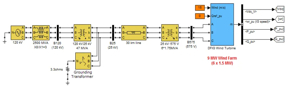
In order to analyze the advantage of adaptive neuro-fuzzy method to control the doubly-fed induction generator in wind energy conversion system, the overall system is simulated using Matlab Simulink software. The example described in this section illustrates the steady-state and dynamic performance of a 9 MW wind farm connected to a distribution system. The wind farm consists of six 1.5 MW wind turbines connected to a 25 kV distribution system exporting power to a 120 kV grid through a 30 km 25 kV feeder. A 2300V, 2 MVA plant consisting of a motor load (1.68 MW induction motor at 0.93 PF) and of a 200 kW resistive load is connected on the same feeder at bus B25. A 500 kW load is also connected on the 575 V bus of the wind farm. The diagram of this system in Matlab Simulink model is illustrated in Fig.5.
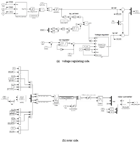
(a) voltage regulating side.
(b) rotor side.
Fig.6. DFIG control in wind energy conversion system.
Wind turbines use a doubly-fed induction machine consisting of a wound rotor induction generator and an AC/DC/AC IGBT-based PWM converter. The stator winding is connected directly to the 60 Hz grid while the rotor is fed at variable frequency through the AC/DC/AC converter. The doubly-fed induction machine technology allows extracting maximum energy from the wind for low wind speeds by optimizing the turbine speed, while minimizing mechanical stresses on the turbine during gusts of wind. The optimum turbine speed producing maximum mechanical energy for a given wind speed is proportional to the wind speed. Another advantage of
the doubly-fed induction machine technology is the ability for power electronic converters to generate or Turbine Data Menu and the Turbine Power Characteristics absorb reactive power, thus eliminating the need for installing capacitor banks as in the case of squirrel-cage induction generators. The terminal voltage will be controlled to a value imposed by the reference voltage (Vref = 1 pu) and the voltage droop
(Xs = 0.02 pu).
are active power control and voltage regulation of DFIG wind turbine using output reactive power control. As illustrated in Fig. 6 rotor side converter manages to follow reference active (Pref) power and voltage (Vref) separately using fuzzy controllers, hysteresis current controller converter and vector control algorithm. Inputs of fuzzy controller are error in active and reactive power or voltage and the rate of changes in errors in any time interval. After the production of reference d- and q-axis rotor currents, they converted to a-b-c reference frame using flux angle, rotor angle and finally slip angle calculation and Concordia and Park transformation matrix. Then they applied to a hysteresis current controller to be compared with actual currents and produce switching time intervals of converter.
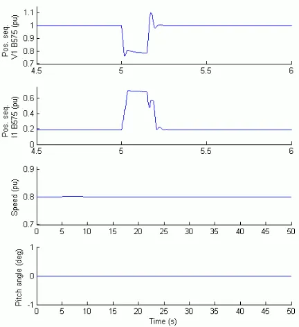
In this simulation, we observe the impact of a single phase-to-ground fault occurring on the 25 kV line. At t=5 s a 9 cycle (0.15 s) phase-to-ground fault is applied on phase A at B25 bus. When the wind turbine is in Voltage regulation mode, the positive sequence voltage at wind turbine terminals (V1_B575) drops to 0.8 pu during the fault, which is above the undervoltage protection threshold (0.75 pu for a t>0.1 s). The wind farm therefore stays in service, as shown in Fig.7. However, if the Var regulation mode is used with Qref=0, the voltage drops under 0.7 pu and the undervoltage protection trips the wind farm. We can now observe that the turbine speed increases. At t=40 s the pitch angle starts to increase to limit the speed, as shown in Fig.8.
Fig. 7. Waveforms of DFIG wind energy during fault at Bus B25 (Voltage Regulation Mode).
Fig. 8. Waveforms of DFIG wind energy during fault at Bus B25 (Var Regulation Mode).
V. CONCLUSIONS
This paper has described the doubly-fed induction generator (DFIG) control in wind energy conversion system using adaptive neuro-fuzzy approach. The wind turbine driven by doubly-fed induction machine is a part of distributed generation which feeds ac power to the distribution network. The system is modeled and simulated in the Matlab Simulink environment in such a way that it can be suited for modeling of all types of induction generator configurations. The model makes use of rotor reference frame using dynamic vector approach for machine model. All power system components and the adaptive neuro-fuzzy controller are simulated in Matlab Simulink software. For studying the performance of controller, different abnormal conditions are applied even the worst case. Simulation results prove the excellent performance of adaptive neuro-fuzzy control unit as improving power quality and stability of wind turbine
VI. REFERENCES
[1] A. Tapia, G. Tapia, J. X. Ostolaza, and J. R. Saenz, ―Modeling and control of a wind turbine driven doubly fed induction
generator,‖ IEEE Transactions on Energy Conversion, Vol.18,
pp. 194-204, 2003.
[2] Y. Lei, A.Mullane, G.Lightbody, and R.Yacamini, ―Modeling of the Wind Turbine With a Doubly Fed Induction Generator
for Grid Integration Studies,‖ IEEE Transactions on Energy
[3] H.Li and Z. Chen, ―Overview of generator topologies for wind
turbines,‖ IET Proc. Renewable Power Generation, vol. 2, no.
2, pp. 123–138, Jun.2008.
[4] L. Mihet-Popa and F. Blaabrierg, ―Wind Turbine Generator Modeling and Simulation Where Rotational Speed is the
Controlled Variable‖, IEEE Transactions on Industry
Applications, Vol. 40, No.1, Jan./Feb. 2004.
[5] S. Kim and E. Kim, ―PSCAD/EMTDC-based modeling and
analysis of a gearless variable speed wind turbine‖, IEEE Trans
Energy Conversion, Vol. 22, No. 2, pp. 421-430, 2007. [6] B.H. Chowary and S. Chellapilla, ―Doubly-fed induction
generator for variable speed wind power generation‖
Transactions on Electric Power System Research, Vol.76,pp. 786-800, Jan . 2006.
[7] B.C. Babu and K.B. Mohanty, ―Doubly-Fed Induction
Generator for Variable Speed Wind Energy Conversion Systems - Modeling & Simulation‖, International Journal of Computer and Electrical Engineering, Vol. 2, No. 1, pp. 1793-8163, February, 2010.
[8] S. Müller, M. Deicke, and R. W. De Doncker, ―Doubly-fed induction generator system for wind turbines‖, IEEE Industry Applications Magazine, May/June 2002.
[9] T. T. Chuong, ―Voltage Stability Investigation of Grid
Connected Wind Farm‖, World Academy of Science,
Engineering and Technology, Vol. 42, pp. 532-536, 2008. [10] M.A. Poller, ―Doubly-Fed Induction Machine Models for
Stability Assessment of Wind Farms”, Power Tech Conference Proceedings of 2003 IEEE Bologna, Vol.3, 6 pp. 23-26 June 2003.
[11] J.G. Slootweg, S. W. H. Haan, H. Polinder, and W.L. Kling.
―General Model for Representing Variable Speed Wind
Turbines in Power System Dynamics Simulations‖. IEEE Trans. on Power Systems, Vol. 18, No. 1, February, 2003. [12] Jang, J.S.R., "ANFIS: Adaptive-Network-based Fuzzy
![Fig.1. Wind turbine characteristics [8].](https://thumb-ap.123doks.com/thumbv2/123dok/413910.525794/2.595.312.533.404.570/fig-wind-turbine-characteristics.webp)
![Fig.2. Typical of doubly-fed induction machine [8].](https://thumb-ap.123doks.com/thumbv2/123dok/413910.525794/3.595.69.293.413.554/fig-typical-of-doubly-fed-induction-machine.webp)