UNIVERSITI TEKNIKAL MALAYSIA MELAKA
THE EFFECT OF SEMI-VERTEX ANGLE ON THE BUCKLING
OF CYLINDER AND CONES
This report submitted in accordance with requirement of the Universiti Teknikal Malaysia Melaka (UTeM) for the Bachelor Degree of Engineering Technology
(Automotive Technology) (Hons.)
by
LOUIS TEO CHEAH HONG B071210492
910707-12-5281
UNIVERSITI TEKNIKAL MALAYSIA MELAKA
BORANG PENGESAHAN STATUS LAPORAN PROJEK SARJANA MUDA
TAJUK: The effect of semi-vertex angle on the buckling of cylinder and cones
SESI PENGAJIAN: 2015/16 Semester 1
Saya LOUIS TEO CHEAH HONG
mengaku membenarkan Laporan PSM ini disimpan di Perpustakaan Universiti Teknikal Malaysia Melaka (UTeM) dengan syarat-syarat kegunaan seperti berikut:
1. Laporan PSM adalah hak milik Universiti Teknikal Malaysia Melaka dan penulis. 2. Perpustakaan Universiti Teknikal Malaysia Melaka dibenarkan membuat salinan
untuk tujuan pengajian sahaja dengan izin penulis.
3. Perpustakaan dibenarkan membuat salinan laporan PSM ini sebagai bahan pertukaran antara institusi pengajian tinggi.
4. **Sila tandakan ( )
SULIT
TERHAD
TIDAK TERHAD
(Mengandungi maklumat yang berdarjah keselamatan atau kepentingan Malaysia sebagaimana yang termaktub dalam AKTA RAHSIA RASMI 1972)
(Mengandungi maklumat TERHAD yang telah ditentukan oleh organisasi/badan di mana penyelidikan dijalankan)
(TANDATANGAN PENULIS)
Alamat Tetap:
Lot 18, Taman Somerset, Phase 2
89500, Penampang, Kota Kinabalu
Sabah
Disahkan oleh:
(TANDATANGAN PENYELIA)
Cop Rasmi:
FAKULTI TEKNOLOGI KEJURUTERAAN
PENGKELASAN LAPORAN PSM SEBAGAI SULIT/TERHAD LAPORAN PROJEK SARJANA MUDA TEKNOLOGI KEJURUTERAAN AUTOMOTIVE (AUTOMOTIVE TECHNOLOGY): LOUIS TEO CHEAH HONG
Sukacita dimaklumkan bahawa Laporan PSM yang tersebut di atas bertajuk “The Effect of Semi-vertex Angle on the Buckling of Cylinder and Cones” mohon dikelaskan sebagai *SULIT / TERHAD untuk tempoh LIMA (5) tahun dari tarikh surat ini.
2. Hal ini adalah kerana ianya merupakan projek yang ditaja oleh syarikat luar dan hasil kajiannya adalah sulit.
Sekian dimaklumkan. Terima kasih.
Yang benar,
________________
Tandatangan dan Cop Penyelia
* Potong yang tidak berkenaan
NOTA: BORANG INI HANYA DIISI JIKA DIKLASIFIKASIKAN SEBAGAI
SULIT DAN TERHAD. JIKA LAPORAN DIKELASKAN SEBAGAI TIDAK
TERHAD, MAKA BORANG INI TIDAK PERLU DISERTAKAN DALAM
iv
DECLARATION
I hereby, declared that this report entitled “The Effect of Semi-vertex Angle on the Buckling of Cylinder and Cones” is the results of my own research except as cited in references.
Signature : ………
Name : ………
v APPROVAL
This report is submitted to the Faculty of Engineering Technology of UTeM as a partial fulfillment of the requirements for the degree of Bachelor of Engineering Technology (Automotive Technology) (Hons.). The member of the supervisory is as follow:
vi ABSTRACT
vii ABSTRAK
viii
DEDICATIONS
ix
ACKNOWLEDGMENTS
First of all, I would like to take this opportunity to express my sincere gratitude to my supervisor Dr. Olawale Ifayefunmi from the Faculty of Engineering Technology, Universiti Teknikal Malaysia Melaka (UTeM) for his guidance, supervision and support towards the process of this final year project report.
I would also like to thank Mr. Shafiq, Mr. Fauzi, Mr. Basri, Mr. Ghazalan and Mr. Azimin, the technicians from Faculty of Engineering Technology and Faculty of Manufacturing Engineering for giving us priority with our project work. Special thanks for the short funding support From UTeM for this project.
x
TABLE OF CONTENTS
DECLARATION... iv
APPROVAL ... v
ABSTRACT ... vi
ABSTRAK ... vii
DEDICATIONS ... viii
ACKNOWLEDGMENTS ... ix
TABLE OF CONTENTS... x
LIST OF FIGURES... xiv
LIST OF TABLE... xvi
LIST OF SYMBOLS AND ABBREVIATIONS ... xvii
CHAPTER 1 ... 1
1.0 Background... 1
1.1 Problem Statement ... 2
1.2 Objectives ... 3
1.3 Scope ... 3
CHAPTER 2 ... 4
2.0 Introduction ... 4
2.1 Background into Buckling of Conical Shells ... 5
2.1.1 Buckling ... 5
xi
2.1.4 Plastic Buckling ... 7
2.2 Buckling of Cone under Axial Compression ... 8
2.2.1 Theoretical Background into Elastic and Plastic Deformation... 8
2.2.1.1 Elastic Critical Load Solution ... 9
2.2.1.2 Plastic Mechanism Solution ... 9
2.2.2 Numerical Analysis on Elastic and Plastic Buckling of Cones under Axial Compression... 10
2.2.3 Experimental Work on Cones under Axial Compression ... 10
2.3 Effect of Semi-vertex Angle on Cones under Axial Compression ... 11
CHAPTER 3 ... 13
3.0 Research Design ... 13
3.1 Preliminary Design ... 14
3.2 Material Selection ... 15
3.3 Manufacturing Process ... 16
3.3.1 Design Sketching ... 16
3.3.2 Specimen Cutting Process... 17
3.3.3 Polishing of Specimens ... 20
3.3.4 Tag Removal ... 21
3.3.5 Gridding of Specimens ... 22
3.3.6 Thickness Measurement Specimens... 23
3.3.7 Specimens Rolling Process ... 24
xii
3.3.9 Further Measurement on Specimens ... 27
3.3.10 Fabrication Process of Test Coupons ... 28
3.3.11 Axial Compression Test ... 30
3.4 Analysis ... 31
3.4.1 Numerical Method ... 31
CHAPTER 4 ... 33
4.0 Introduction ... 33
4.1 Pre-test Measurement ... 33
4.1.1 Thickness Measurement on Shell Structures ... 33
4.1.2 Height Measurement on Shell Structures... 35
4.1.3 Slant Length Measurement on Shell Structures ... 37
4.1.4 Inner Diameter Measurement on Shell Structures... 39
4.1.5 Outer Diameter Measurement on Shell Structures ... 41
xiii
APPENDIX F ... 70
APPENDIX G... 71
xiv
LIST OF FIGURES
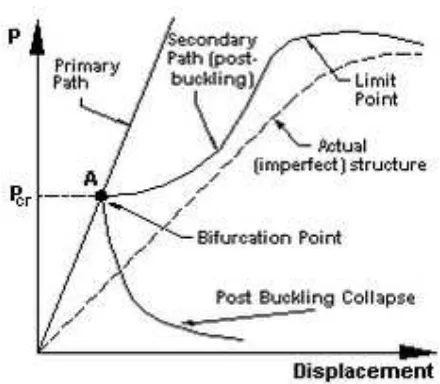
Figure 2.1: Characteristics of Bifurcation Buckling ... 6
Figure 2.2: Characteristics of Snap-through Buckling... 7
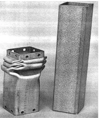
Figure 2.3: Characteristics of Plastic Buckling ... 7
Figure 2.4: Characteristics of Elastic and Plastic Deformation ... 8
Figure 2.5: Typical Collapse Mode of Axially Compressed Cone, ... 11
Figure 2.6: Variation of Critical and Limit Loads with Semi-vertex Angle. Note, (SS-r) = Radially Fixed, (FF-(SS-r) = Radially Free. (Chryssanthopoulos and Spagnoli, 1997) ... 12
Figure 3.1: Project Flow Chart ... 13
Figure 3.2: Sample Templates ... 14
Figure 3.3: Sketched Drawing of Specimens ... 16
Figure 3.4: 1mm Mild Steel Sheet ... 17
Figure 3.5: Hydraulic Shear ... 17
Figure 3.6: The Cutting Sequence on FlowCut Software ... 18
Figure 3.7: The Cutting Process ... 19
Figure 3.8: The Cut Specimens ... 19
Figure 3.9: WD-40 used for Polishing the Cut Out Specimens to Prevent Rusting .. 20
Figure 3.10: Removing of the Tag ... 21
Figure 3.11: Floor-mounted Utility Grinding Machine ... 22
Figure 3.12: Griding of the Specimens ... 23
Figure 3.13: Griding of the Specimens ... 23
Figure 3.14: Thickness Measurement ... 24
Figure 3.15: Rolling Process of Cylindrical Specimens ... 25
Figure 3.16: Rolling Process of Angled Specimens... 25
Figure 3.17: Welded Specimen ... 26
Figure 3.18: Outer Diameter Measurement ... 27
Figure 3.19: Height Measurement ... 28
Figure 3.20: Test Coupons Cutting Process ... 29
Figure 3.21: Test Coupons ... 29
Figure 3.22: Cyllindrical Shell on Instron Machine... 30
Figure 3.23: Equivalent Cylinder (left) and Cone (right) Created using ABAQUS FE Software ... 32
Figure 4.1: Intersection Point of Thickness Measurement ... 34
Figure 4.2: Thickness Measurement Points ... 34
Figure 4.3: Height Measurement Points in Vertical Direction for Cylindrical Shell. 35 Figure 4.4: Top View of the Shell with Measurement Points Labelled on the Circumference (Height) ... 36
xv
Circumference (Slant Length) ... 38 Figure 4.7: Inner Diameter Measurement using Vernier Caliper ... 39 Figure 4.8: Top View of the Shell with Measurement Points Labelled on the
Circumference (Inner Diameter) ... 40 Figure 4.9: Outer Diameter Measurement using Vernier Caliper ... 41 Figure 4.10: Top View of the Shell with Measurement Points Labelled on the
xvi
LIST OF TABLE
Table 2.1: Comparisons of Buckling Loads for Conical Shells (Chung, 2001) ... 12
Table 3.1: Properties of Mild Steel ... 15
Table 3.2: Advantages of Mild Steel... 15
Table 3.3: Types of Analysis ... 31
Table 3.4: Boundary Condition ... 31
Table 3.5: Geometry of Specimens (Analysis 1) ... 32
Table 3.6: Geometry of Specimens (Analysis 2) ... 32
Table 4.1: Summary of Thickness Measurements for All Specimens ... 35
Table 4.2: Summary of Height Measurements for All Specimens ... 36
Table 4.3: Summary of Slant Length Measurement for Specimens 5⁰to 20⁰ ... 38
Table 4.4: Summary of Inner Diameter Measurements for All Specimens ... 40
Table 4.5: Summary of Outer Diameter Measurements for All Specimens ... 42
Table 4.6: Collapse Load of Specimens ... 43
Table 4.7: Collapse Load of Specimens (Analysis 1) ... 47
Table 4.8: Collapse Load of Specimens (Analysis 2) ... 47
Table 4.9: Comparison of Collapse Load between Numerical and Experimental Results ... 47
xvii
SBM = Shape-Based Matching
= Critical buckling load
E = Young’s Modulus
t = Shell wall thickness = Semi-vertex angle = Poisson’s ratio
= Squash load
= Top radius of the cone
= Yield stress
= Limit load
MPa = Mega pascal
GPa = Giga pascal
1
CHAPTER 1
INTRODUCTION
1.0 Background
Conical shells are often used as transition elements joining cylinders of different diameters. They find applications in pressure vessels, offshore platforms, pipelines and transition elements between cylinders of different diameters (Blachut and Ifayefunmi, 2009). For such application, their failure by buckling is of great importance to the structural engineer (Rotter, 2002). Fundamentally, they are subjected to a variety of loading conditions including axial compression, external pressure, and torsion. Under these loads, the buckling strength of cones becomes one of the crucial design considerations (Blachut, 2010). This technical challenge has made significant research in the areas of mechanical behaviour and failure of thin shell structure, under the applied load (Rotter, 2002). For thin-walled structures, such as small deviations of the structure from its formal unloaded shape, may also have quite important effects on the load at which buckling will occur (National Aeronautics and Space Administration, 1968). Thus, it is essential that the buckling behaviour of shells is properly understood so that suitable design methods can be achieved (Teng and Rotter, 2003). Shell analysis and design often relies on linear or non-linear numerical stability calculations for predicting the response of thin shells subjected to loads that may lead to buckling failure. Although physical experimentation remains vital in order to display phenomena that cannot be reproduced numerically, to acknowledge unforeseen patterns of behaviour and to verify methods of analysis, the use of numerical models in analysing shell buckling response is widespread (Chryssanthopoulos and Spagnoli, 1997).
2 axial compression.
1.1 Problem Statement
Buckling is one of the complicated phenomena in solid mechanics. This aspect is dangerous for shells that are thin and subjected to compressive force (Boorboor, et al., 2012). For the specific case of cylindrical panels, the buckling and post buckling behaviour has been researched in detail, whereas limited studies is available for the more general case of conical panels (Spagnoli and Chryssanthopoulos, 1998). As a result, conical shells have received much less interest regardless of their use in areas where static stability can be one of the main design constraints (Blachut, 2012). Instability of structural element is one of the factors that limit the amount to which the structures can be loaded or deform (Ifayefunmi, 2014). Due to relatively low slenderness of the specimens, the failure was in all cases greatly affected by plasticity effects (Chryssanthopoulos and Poggi, 2000). Besides, as the cone angle increases, the failure load reduces under the influence of boundary condition (Ifayefunmi and Blachut, 2011). Different parameters change the buckling behaviour of the shell, making it difficult to achieve a general depiction (Golzan and Showkati, 2008).
3 1.2 Objectives
Based on the background and problem statement listed, the objectives of this research study are as follows:
1. To manufacture cylinder and cones with different semi-vertex angles.
2. To investigate the effect of semi-vertex angle on the buckling behaviour of axially compressed conical shells.
3. To compare results between experimental, numerical and theoretical approach.
1.3 Scope
4
CHAPTER 2
LITERATURE REVIEW
2.0 Introduction
5
successfully carry out buckling analysis of conical shells, it is important to carefully study and understand the behaviour of the shell structure (Ifayefunmi, 2014).
2.1 Background into Buckling of Conical Shells
2.1.1 Buckling
6
As shown in Figure 2.1, the linear buckling analysis assumes the existence of a bifurcation point where the primary and secondary loading paths intersect. At this point, more than one equilibrium position is possible. The primary path is not usually followed after loading exceeds this point and the structure is in the post-buckling state. The slope of the secondary path at the bifurcation point determines the nature of the post-buckling. A positive slope indicates that the structure will have post buckling strength whilst a negative slope means that the structure will simply collapse.
Figure 2.1: Characteristics of Bifurcation Buckling
2.1.3 Snap-through Buckling
7
Figure 2.2: Characteristics of Snap-through Buckling
2.1.4 Plastic Buckling
When a material is loaded in compression it may buckle when a critical load is applied. If loading is performed at constant strain-rate, this initial buckling will be elastic and will be recoverable when the applied compressive stress is removed. As the applied load increases on the material, it will eventually become large enough to cause the material to become unstable and buckle. This deformation is permanent and cannot be recovered when the load is removed. Plastic deformation of thin-walled sections is demonstrated clearly on the left specimen in Figure 2.3 (Wright, 2005). Generally, a more significant load is the ultimate load of the structure, which may be reached when the material fails plastically or when the structure collapses (National Aeronautics and Space Administration, 1968).