UNIVERSITI TEKNIKAL MALAYSIA MELAKA
MONITORING AND EVALUATION OF THE EFFECT OF
CRACK ON THE BUCKLING BEHAVIOUR OF WELDED
CYLINDRICAL STRUCTURES
This report submitted in accordance with requirement of the Universiti Teknikal Malaysia Melaka (UTeM) for the Bachelor Degree of Engineering Technology
(Maintenance Technology)(Hons.)
by
NOREHAN BINTI KASIMAN B071110292
920523035766
UNIVERSITI TEKNIKAL MALAYSIA
BORANG PENGESAHAN STATUS LAPORAN PROJEK SARJANA MUDA
( )
(Mengandungi maklumat TERHAD yang telah ditentukan oleh organisasi/badan di mana penyelidikan dijalankan) TAJUK: Monitoring and Evaluation of the Effect of Crack on the Buckling Behaviour of Welded Cylindrical Structures
SESI PENGAJIAN: 2014/15 Semester 1
Saya Norehan Binti Kasiman
mengaku membenarkan Laporan PSM ini disimpan di Perpustakaan Universiti Teknikal Malaysia Melaka (UTeM) dengan syarat-syarat kegunaan seperti berikut:
1. Laporan PSM adalah hak milik Universiti Teknikal Malaysia Melaka dan penulis. 2. Perpustakaan Universiti Teknikal Malaysia Melaka dibenarkan membuat salinan
untuk tujuan pengajian sahaja dengan izin penulis.
3. Perpustakaan dibenarkan membuat salinan laporan PSM ini sebagai bahan pertukaran antara institusi pengajian tinggi.
4. **Sila tandakan ( )
(Mengandungi maklumat yang berdarjah keselamatan atau kepentingan Malaysia sebagaimana yang termaktub dalam AKTA RAHSIA RASMI 1972)
TERHAD
TIDAK TERHAD
DECLARATION
I hereby, declared that this report entitled “Monitoring and Evaluation of the Effect of Crack on the Buckling Behaviour of Welded Cylindrical Structures” is the
results of my own research except as cited in references.
Signature : ……….
Author’s Name : ………
APPROVAL
This report is submitted to the Faculty of Engineering Technology of UTeM as a partial fulfillment of the requirements for the degree of Bachelor of Engineering Technology (Maintenance Technology) (Hons.). The member of the supervisory is as follow:
i
ABSTRAK
ii
ABSTRACT
iii
DEDICATION
iv
ACKNOWLEDGEMENT
First and foremost, I would like to take this opportunity to express my sincere acknowledgement to my supervisor Dr. Olawale Ifayefunmi from the Faculty of Engineering Technology, Universiti Teknikal Malaysia Melaka (UTeM) for his essential supervision, support and encouragement towards the completion of this final year project report.
Special thanks to UTeM short term grant funding for the financial support throughout this project. Particularly, I would also like to express my deepest gratitude to Mr. Fauzi Ibrahim and Mr. Fakhrulnaim, the technicians from fabrication laboratory, Faculty of Engineering Technology.
v
2.0 Introduction of buckling in thin-walled shell of cylindrical structure 4
2.1 Cracks 5
2.2 Buckling of perfect cylinder under axial compression 6
2.3 Buckling of imperfect cylinder under axial compression 7
vi
CHAPTER 3: METHODOLOGY 12
3.0 Research design 12
3.1 Conceptual design 13
3.1.1 Design of welded cylindrical structure using CAD 14
3.2 Material selection 15
3.3 Design and manufacturing process of test specimen 16 3.3.1 Cutting process of mild steel plate for manufacturing of hollow 16
cylinder
3.3.2 Polishing process of mild steel plate 18 3.3.3 Grid line process on mild steel plate for pre-test measurement 18
process
3.3.4 Rolling process of mild steel plate 19
3.3.5 Welding process of hollow cylinder 21
3.4 Axial compression test 22
CHAPTER 4: RESULTS AND DISCUSSION 24
4.0 Introduction 24
4.1 Pre-test measurement 24
4.1.1 Thickness measurement for steel plate of shell structure 24 4.1.2 Diameter measurement of steel shell structure 26 4.1.3 Axial length measurement of steel shell structure 28
4.1.4 Crack area measurement 29
4.2 Summary of data obtained from the pre-test measurement 31
vii
LIST OF TABLES
3.1 Advantages of mild steel grade A36 in engineering applications 15
3.2 Properties of mild steel grade A36 15
4.1 Average thickness of steel plate for each steel shell cylindrical model 25
4.2 Diameter measurement of steel shell structure 27
4.3 Axial length measurement of steel shell structures 29 4.4 Crack length introduced for each cylindrical model 30 4.5 Data obtained for calculated crack area and crack width measurement 31
using inverted microscope
4.6 Pre-test measurements data obtained from all cylindrical shells 32 introduced
viii
LIST OF FIGURES
2.1 Typical buckling modes for axially compressed perfect cylinders 5 (Rotter, 2002)
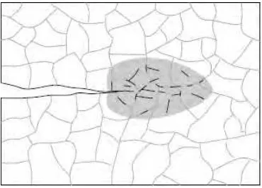
2.2 Micro separations of nucleation in a small area around an existing 6 dominant crack (Deshpande et al., 2006)
2.3 Load-end shortening relationship (Rotter, 2002) 7
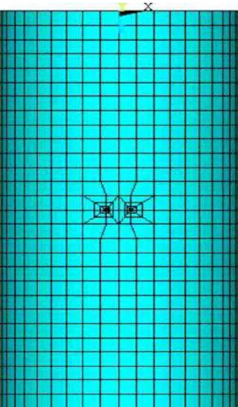
2.4 Computation model of cylindrical shells with a circumferential crack 8 (Vaziri & Estekanchi, 2006)
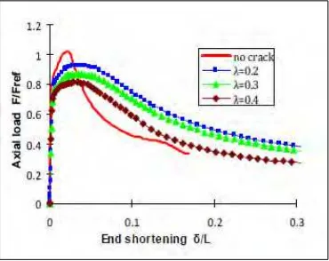
2.5 Load-end shortening behavior of cylindrical shells with and without 9 crack at various crack length (Shariati et al., 2010)
3.1 Project work flow chart 12
3.2 Concept design of cylindrical shell structure 13
3.3 3D drawing of specimen model 14
3.4 Illustrations of the design and manufacturing process 16
3.5 Water jet cutting machine 17
3.6 Mild steel plate with specified geometrical dimension 17
3.7 Grid line drawn on mild steel plate 18
3.8 Equipment needed to draw grid line on mild steel plate 19 3.9 Rolling process of mild steel plate by using conventional roller 20
machine
3.10 Hollow cylinder of mild steel 21
3.11 Percentage of axial crack length to the cylinder axial length (2a/L) 22 3.12 Specimen models welded using MIG welding process 22 3.13 Axial compression test on cylindrical structural model using Instron 23
ix
LIST OF FIGURES
4.1 Grid line of the steel plate for thickness measurement 25 4.2 End point at the circumference of the cylindrical steel structure 26
for diameter measurement
4.3 Top view of the shell structure shows the end point labeled for diameter 27 measurement
4.4 Measurement of axial length from top point to bottom point of 28 specimen
4.5 Image of crack width measurement by using inverted microscope 30 4.6 Compression test of cylindrical shell with compression force applied 33
from the bottom
4.7 Overview of experimental test procedure 34
4.8 Graph of experimental load against axial shortening (C1) 35 4.9 Graph of experimental load against axial shortening (C2) 36 4.10 Graph of experimental load against axial shortening (C3) 36 4.11 Graph of experimental load against axial shortening (C4) 37 4.12 Graph of experimental load against axial shortening (C5) 37 4.13 Graph of experimental load against axial shortening (C6) 38 4.14 Graph of experimental load against axial shortening 39
4.15 Collapsed mode with D/t≈100 39
x
LIST OF ABBREVIATIONS, SYMBOLS AND
NOMENCLATURE
ASTM - American Society for Testing and Materials CAD - Computer Aided Design Software
3D - 3-Dimensional drawing
A - Crack area
D - Diameter
L - Axial length
xi
LIST OF ABBREVIATIONS, SYMBOLS AND
NOMENCLATURE
N - Newton
t - Wall thickness of cylinder
Z - Width of crack
1 CHAPTER 1
INTRODUCTION
1.0 Background
Cylindrical structures is one of the most common and popular structural geometry used in industrial application such as pipelines, marine structures, aerospaces, large dams, cooling towers, and liquid-retaining structures (Allahbakhsh & Shariati, 2014; Blachut, 2011). When in use, cylindrical shell structures are subjected to different loading conditions such as axial compression, external pressure, internal pressure, torsion etc (Blachut, 2014). For such application, their failure by buckling is of great importance to the structural designer. This technical challenge has sprawned up significant research in the areas of the mechanical behavior and failure of thin shell structure, under the applied load. To successfully carry out buckling analysis of cylindrical shell structure, it is important to understand the factors responsible for the buckling problem. According to (Rotter, 2002) cylindrical shells structures are often subjected to compressive stresses in the direction of the cylinder axis, which can be either uniform or varying throughout the cylinder. The buckling strength of a thin cylindrical shell under axial compression is particularly sensitive to imperfections such as crack in the shell.
2 1.1 Problem statement
It is a known fact that the presence of crack will affect the buckling behavior of structural components resulting in failure of the structures especially cylindrical shell structures (Deshpande, et al., 2006). Small deviations from the theoretical geometry and loading can result in a considerable reduction in limit load for shells (Farshad, 1994). According to (Vafai & Estekanchi, 1996) the presence of cracks in a shell structure can play the role of geometrical imperfection and thus reduce the load carrying capacity of a shell structure. Referring to (Jahromi & Vaziri, 2012), cylindrical structures subjected to axial compression are very sensitive to defect in the structural member. From the structural point of view, the biggest impact of crack is the excessive stress, which could result in overall structure failure. Crack could also lead to large localized deformation (e.g. local buckling or plastic deformation), which can alter the structure’s load carrying capacity (Alinia, et al., 2007). Thus, there is a driving need to better understand the effect of crack on the mechanical behavior and structural performance of shells.
3 1.2 Objectives
Based on the background and problem statement stated above, the objectives of this experimental research are as follow:
i. To manufacture steel cylindrical shell models with axial crack length introduced.
ii. To investigate the effect of axial crack length introduced on the load carrying capacity of the steel cylindrical shell structure under axial compression.
1.3 Scope
The scope of this project work is purely experimental work to investigate the effect of axial crack length on the load carrying capacity of welded mild steel cylindrical shell structure subjected to axial compression. The material used for the cylindrical structures is mild steel. All cylindrical specimens are manufactured to have a nominal thickness of 1mm.
4 CHAPTER 2
LITERATURE REVIEW
5 Figure 2.1: Typical buckling modes for axially compressed perfect cylinders
(Rotter, 2002)
2.1 Cracks
6 Figure 2.2: Micro separations of nucleation in a small area around an existing
dominant crack (Deshpande, et al., 2006)
2.2 Buckling of perfect cylinder under axial compression
Better understanding of buckling for thin-walled cylindrical shells under axial compression is an important factor for structural designer especially in aerospace structure area because the cylindrical structural components mainly in used. Since then the phenomena of shell buckling became the main important design constraint for aerospace structures (Hoff, 1967).
7 Figure 2.3: Load-end shortening relationship (Rotter, 2002)
Linear pre-buckling path is suddenly terminated as the shell bifurcates into a non-symmetric mode (see Figure 2.1), with several full waves of buckling around the circumference, and usually several waves up the height. During buckling process, the load falls very rapidly, and the cylinder actually increases in length (Figure 2.3) as the displacements normal to the surface grow. When the maximum load of cylindrical structure reached at its point, bifurcation after bifurcation occurs on the shell structures (Rotter, 2002).
2.3 Buckling of imperfect cylinder under axial compression
8 According to this research paper, they emphasize that when the cylindrical structures being exposed to the internal pressure, it gives the stabilizing effect against the local buckling for circumferential cracked cylindrical shell. Figure 2.4 shows the computation model of cylindrical shells with circumferential cracked shell structured.
Figure 2.4: Computation model of cylindrical shells with a circumferential crack (Vaziri & Estekanchi, 2006)
9 Figure 2.5: Load-end shortening behavior of cylindrical shells with and without
crack at various crack length (Shariati, et al., 2010)
The existence of longitudinal crack with the ratio of λ = 0.4 on the cylindrical shell reduces the shell buckling load to 76% of the buckling load of perfect cylinder. In longitudinal crack, the change in crack length and increasing λ has major effect on the buckling load. Followed by λ = 0.2 and 0.3 the results depicted the same pattern with λ = 0.4 on the cylindrical shell buckling load.