First published 2016
Copyright © 2016 by Centre for Advanced Research on Energy (CARe)
All rights reserved. No part of this publication may be reproduced, stored in a retrieval system, or transmitted, electronic, mechanical photocopying, recording or otherwise, without the prior permission of the Publisher.
ISBN: 978-967-0257-70-9 (online) Published and Printed in Malaysia by: Centre for Advanced Research on Energy,
Faculty of Mechanical Engineering, Universiti Teknikal Malaysia Melaka, Hang Tuah Jaya, 76100 Durian Tunggal, Melaka, MALAYSI A.
Proceedings of Mechanical Engineering Research Day 2016
ii
FOREWORD BY THE EDITORS-IN-CHIEF
This Open Access e-Proceeding contains a compilation of 105 selected papers from the Mechanical Engineering Research Day 2016 (MERD’16) event, which is held in Kampus Teknologi, Universiti Teknikal Malaysia Melaka (UTeM) - Melaka, Malaysia, on 31 March 2016. The theme chosen for this event is ‘I DEA. I NSPI RE. I NNOVATE’.
I t was gratifying to all of us when the response for MERD’16 is overwhelming as the technical committees received more than 200 submissions from various areas of mechanical engineering. After a peer-review process, the editors have accepted 105 papers for the e-proceeding that cover 7 main themes. This open access e-Proceeding can be viewed or downloaded at www3.utem.edu.my/ care/ proceedings. We hope that these proceeding will serve as a valuable reference for researchers.
With the large number of submissions from the researchers in other faculties, the event has achieved its main objective which is to bring together educators, researchers and practitioners to share their findings and perhaps sustaining the research culture in the university. The topics of MERD’16 are based on a combination of fundamental researches, advanced research methodologies and application technologies.
As the editor-in-chief, we would like to express our gratitude to the editorial board and fellow review members for their tireless effort in compiling and reviewing the selected papers for this proceeding. We would also like to extend our great appreciation to the members of the Publication Committee and Secretariat for their excellent cooperation in preparing the proceeding of MERD’16.
Thank you
iii
EDITORIAL BOARD
Editors-in-Chief
Mohd Fadzli Bin Abdollah – FKM, UTeM, Malaysia Mohd Azli Bin Salim – FKM, UTeM, Malaysia Tee Boon Tuan – FKM, UTeM, Malaysia
Editors
Abd Rahman Bin Dullah – FKM, UTeM, Malaysia
Fatimah Al-Zahrah Binti Mohd Sa'at – FKM, UTeM, Malaysia Ghazali Bin Omar – FKM, UTeM, Malaysia
Mohd Azman Bin Abdullah – FKM, UTeM, Malaysia Mohd Khairi Bin Mohamed Nor – FKM, UTeM, Malaysia Mohd Zulkefli Bin Selamat – FKM, UTeM, Malaysia Muhd Ridzuan Bin Mansor – FKM, UTeM, Malaysia Noreffendy Bin Tamaldin – FKM, UTeM, Malaysia Rafidah Binti Hasan – FKM, UTeM, Malaysia Rainah Binti I smail – FKM, UTeM, Malaysia Reduan Bin Mat Dan – FKM, UTeM, Malaysia
Shamsul Anuar Bin Shamsudin – FKM, UTeM, Malaysia Siti Hajar Binti Sheikh Md Fadzullah – FKM, UTeM, Malaysia Sivakumar A/ L Dhar Malingam – FKM, UTeM, Malaysia Suhaila Binti Salleh – FKM, UTeM, Malaysia
Proceedings of Mechanical Engineering Research Day 2016
iv
REVIEWERS
Abd Salam Bin Md Tahir – FKM, UTeM, Malaysia Abdul Munir Hidayat Syah Lubis – FTK, UTeM, Malaysia Ahmad Rivai – FKM, UTeM, Malaysia
Amrik Singh A/ L Phuman Singh – FKM, UTeM, Malaysia Azma Putra – FKM, UTeM, Malaysia
Faiz Redza Bin Ramli – FKM, UTeM, Malaysia
Fatimah Al-Zahrah Binti Mohd Sa'at – FKM, UTeM, Malaysia Ghazali Bin Omar – FKM, UTeM, Malaysia
Hidayat Bin Zainuddin – FKE, UTeM, Malaysia I mran Syakir Mohamad – FKM, UTeM, Malaysia Jaharah Binti A. Ghani – UKM, Malaysia
Kamarul Ariffin Bin Zakaria – FKM, UTeM, Malaysia Mariam Binti Md Ghazaly – FKE, UTeM, Malaysia Md. Fahmi Bin Abd. Samad – FKM, UTeM, Malaysia Mohd Ahadlin Bin Mohd Daud – FKM, UTeM, Malaysia Mohd Asyadi 'Azam Bin Mohd Abid – FKP, UTeM, Malaysia Mohd Azli Bin Salim – FKM, UTeM, Malaysia
Mohd Azman Bin Abdullah – FKM, UTeM, Malaysia Mohd Basri Bin Ali – FKM, UTeM, Malaysia
Mohd Fadzli Bin Abdollah – FKM, UTeM, Malaysia Mohd Haizal Bin Mohd Husin – FKM, UTeM, Malaysia Mohd Khairi Bin Mohamed Nor – FKM, UTeM, Malaysia Mohd Nizam Bin Sudin – FKM, UTeM, Malaysia
Mohd Warikh Bin Abd Rashid – FKP, UTeM, Malaysia Mohd Zaid Bin Akop – FKM, UTeM, Malaysia
Mohd Zulkefli Bin Selamat – FKM, UTeM, Malaysia
Muhammad I lman Hakimi Chua Bin Abdullah – FTK, UTeM, Malaysia Noraiham Binti Mohamad – FKP, UTeM, Malaysia
Norfariza Binti Ab Wahab – FTK, UTeM, Malaysia Nurin Wahidah Binti Mohd Zulkifli – UM, Malaysia Olawale I faye Funmi – FTK, UTeM, Malaysia Omar Bin Bapokutty – FKM, UTeM, Malaysia Rafidah Binti Hasan – FKM, UTeM, Malaysia Rainah Binti I smail – FKM, UTeM, Malaysia Reduan Bin Mat Dan – FKM, UTeM, Malaysia Roszaidi Bin Ramlan – FKM, UTeM, Malaysia
Siti Hajar Binti Sheikh Md Fadzullah – FKM, UTeM, Malaysia Sivakumar A/ L Dhar Malingam – FKM, UTeM, Malaysia Suhaila Binti Salleh – FKM, UTeM, Malaysia
v
TABLE OF CONTENTS
FOREWORD BY THE EDI TORS-I N-CHI EF ……… ii
EDI TORI AL BOARD ……… iii
REVI EWERS ……… iv
TABLE OF CONTENTS ……… v
Theme 1 : Aut omot ive 01. The effect of temperatures and extraction time on bio oil extracted from banana peel wastes. H.A. Hamid, N.A.B. Masripan, M.F.B. Abdollah, R. Hasan, G. Omar ……….…… 1
02. Field test of regenerative suspension system on an actual vehicle. J.F. Jamil, M.A. Abdullah, A.E. Mohan ………...……….…… 3
03. The improvement and laboratory testing of regenerative suspension system . A.E. Mohan, M.A. Abdullah, J.F. Jamil ……….…….……… 5
04. Performance of compressed natural gas (CNG) engine with pre chamber. M.S. Ali, M.T. Musthafah, A.M. Mohd Shafei, A.M.T. Khairil, N.F.M. Nor, R.A. Bakar ... 7
05. Validation of automotive passive engine mount system. M. Hafiz Harun, M.Z. Sariman, A.K. Mat Yamin, R. Yunos, M.A. Azhari, F. Ahmad ……….…. 9
06. Optimization of friction coefficient of kenaf/ epoxy composites as an alternative friction material using Taguchi method. A. Mustafa, M.F.B. Abdollah, H. Amiruddin, F.F. Shuhimi, N.A.M. Tahir, N. Muhammad, S.E. Mat Kamal, N. I smail ………....…… 11
07. Application of waste chicken fat in base catalyzed (potassium hydroxide) biodiesel production. N.H. Razak, M.I .A.K.M. Safari, H.A. Merican, F. Ghafar, N.I . Zulkafli …….……….…… 13
08. Brake insulator analysis in reducing internal brake squeal noise. M.A. Abdullah, A.R. Efariani ……….……….…….… 15
09. I nfluence of tire stiffness and sprung mass on ride quality. A. Md Saad, M.A. Salim, M.H. Harun, M.R. Mansor, M.Z. Akop, M.T. Musthafah ………..…… 17
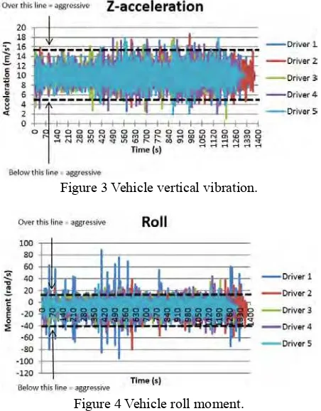
10. Driving behaviour analysis of young vehicle drivers. M.A. Abdullah, M.A.H. Abdul Rahim ………..……….……… 19
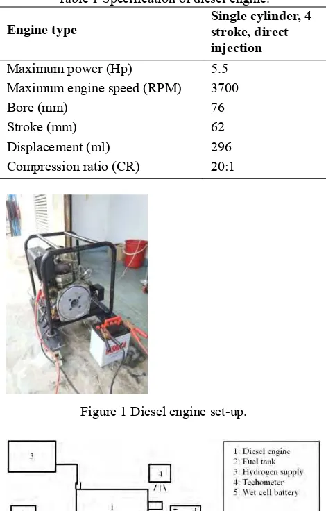
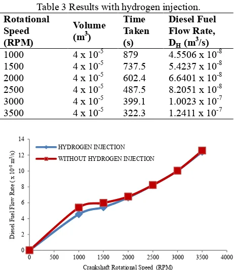
11. Effect of hydrogen injection on diesel engine performance intake: Preliminary result . M.N.M. Norani, B.T. Tee, M.Z. Zulfattah, M.N.A. Saadun, A. Hussain, M.N. Mansor …………..…… 21
Proceedings of Mechanical Engineering Research Day 2016
vi
13. Experimental I nvestigation of engine performance and emission for biodiesel at various storage conditions.
N. Tamaldin, A.S. Mohamad, Y. Humairak , M.H.M. Husin, M.F.B. Abdollah …………..……..…….... 25
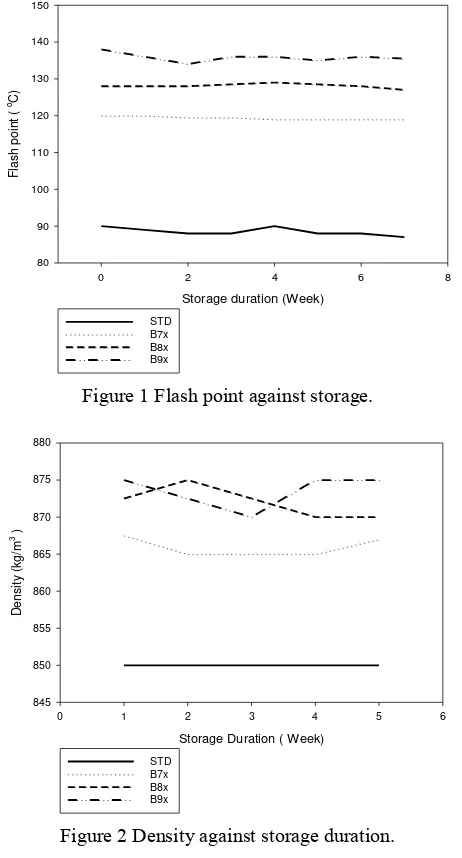
14. Effect of storage duration on the fuel properties of different biodiesel blends.
N. Tamaldin, F. Harun, Y. Humairak, M.H.M. Husin, M.F.B. Abdollah ………..…… 27
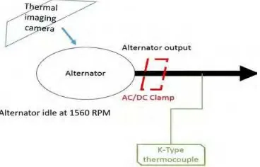
15. The effect of increasing current to temperature of alternator.
R.K. Mazlan, R.M. Dan, M.Z. Zulfattah, A.H.A. Hamid ……….………….…….. 29
16. Experimental study of noise level for car engines.
M.R. Rizainal, M.A. Salim, A. Md Saad, M.R. Mansor, M.Z. Akop, M.T. Musthafah,
I .R.A. Rosszainily ………..……….…..… 31
Theme 2: Computer Modelling and Simulation
17. I nfluence of halo and source/ drain implant variations on the drive current in p-channel vertical double gate MOSFET.
K.E. Kaharudin, F. Salehuddin, A.S.M. Zain, M.N.I A. Aziz……….. 33
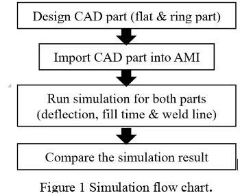
18. Comparison of flow analysis between flat and ring plastic parts using moldflow software.
Mohd Amran Md Ali, Mohd Faizal Khalik, Mariam Md Ghazaly, Zulkeflee Abdullah ………..… 35
19. Study of thinning effect from deep drawing process on crash analysis.
R.M. Amman, M.F. Halim, D. Sivakumar, I . Abu-Shah, M.S. Sulaiman, H. Samekto …………...…… 37
20. Design, simulation and analysis of disc rotor using anycasting software.
N.F.B.W. Anuar, N. Jani, M.R.M. Kamal ……….……….. 39
21. Linear and nonlinear dynamic model of a gantry crane system.
H.I . Jaafar, Z. Mohamed, M.A. Ahmad, R. Ghazali, A.M. Kassim ……….……….. 41
22. Finite Element Modelling of microscale and macroscale on deformation of composite material.
Ab Ghani Ahmad Fuad, Reduan Mat Dan, M.I . Shariff, Tan Joon Tak ………..……….. 43
23. Performance analysis of neural network models for sustainable manufacturing practices (SMP) and economy performances.
N.H. Abu, A.S.M. Jaya, M.R. Muhamad ……….……… 46
Theme 3: Design and Optimization
24. Multiobjective optimization of injection moulding process parameters using Grey Fuzzy method. Mohd Amran Md Ali, Noorfa I dayu Mohd Ali, Mariam Md Ghazaly, Zulkeflee Abdullah,
Suhaila Yacob ………..……….. 48
25. Force optimization of the permanent magnet switching flux (PMSF) and switching reluctance (SR) actuators using Finite Element Analysis.
vii
26. Force optimizations of a tubular linear reluctance actuator (TLRA) and tubular linear permanent magnet actuator with Halbach array (TLPM).
A.H. Jamaludin, M.M. Ghazaly, T.A. Yahya, A.C. Amran, Z. Abdullah, M.A.M. Ali, N.M. Ali ….…… 52
27. Development of a RFI D inter-office document’s delivery system via mobile robot.
M.M. Ghazaly, K.Y. Soo, Z. Abdullah, M.R. Yaacob, C.C. Ho, C.Y. Ng ……….……… 54
28. Optimization using L9 Taguchi method toward threshold voltage of 18nm gate length SOI p-channel MOSFET.
M.N.I .A. Aziz, F. Salehuddin, A.S.M. Zain, K.E. Kaharuddin, A.R. Hanim, H. Hazura,
S.K. I dris …….……….. 56
29. Structural design and analysis of autonomous guided vehicle (AGV) for parts supply.
Mohd Suffian Ab Razak, Khairul Hazwan Mohd Rasit, Nur Rashid Mat Nuri, M.Z.A Rashid ……..… 58
30. Design strategy for concept design of hybrid bio-composite automotive anti-roll bar using TRI Z. M.T. Mastura, S.M. Sapuan, M.R. Mansor, A.A. Nuraini ……….………. 60
31. Development of a rotary axis mechanism for wire EDM turning (WEDT)
M. Akmal, R. I zamshah, M.S. Kasim, M. Hadzley, M. Amran, A. Ramli ……… 62
32. Optimal PI D sliding surface for sliding mode control based on particle swarm optimization algorithm for an electro-hydraulic actuator system.
C.C. Soon, R. Ghazali, H.I . Jaafar, S.Y.S Hussien ……….………..……… 64
33. Experimental analysis of 3D gantry crane system via optimal PI D and PD controller by PSO.
S.Y.S. Hussien, R. Ghazali, H.I . Jaafar, C.C. Soon ……….………. 66
34. Strength and porosity of additively manufactured PLA using a low cost 3D printing.
H.A. Habeeb, M.R. Alkahari, F.R. Ramli, R. Hasan, S. Maidin ……….……… 69
35. Optimization of warping deformation in open source 3d printer using response surface method. M.A. Nazan, F.R. Ramli, M.R. Alkahari, M.N. Sudin, M.A. Abdullah ……….. 71
36. Dimensional inspection of 3D laser scanner, coordinate measuring machine and image processing.
M.K. Sued, M.Z. Mohd Noh, M.F. Dimin ……….…..……… 73
Theme 4: Energy Conversion and Management
37. Studying air flow distribution in a tray dryer through CFD simulation.
S. Misha, S. Mat, M.H. Ruslan, E. Salleh, K. Sopian ………..… 75
38. Evaluation of impact based energy harvesting using a piezoelectric ceramic disc.
Ali Mohammed abdal-Kadhim, Kok Swee Leong ………..……….. 77
39. Performance analysis of portable power generator by using TEG module.
Siti Halma Johari, Mohd Faiz Che Pa, Khalil Azha Mohd Annuar, Suziana Ahmad,
Proceedings of Mechanical Engineering Research Day 2016
viii
40. Peltier and seebeck efficacy of hot and cold air system for portable O-REF (oven & refrigerator) application.
M.H. Harun, K.A.M. Annuar, M.F.M.A. Halim, M.H.C. Hasan, M.S.M. Aras, M.F. Yaakub ………..… 81
41. Potential co-processing of coconut shell and sugarcane residue as a solid biofuel.
Nona Merry M. Mitan, Mohd Nur Shafiq Ahmad Razimi ……….………. 83
42. Application of limestone as based catalyst in transesterification of rubber seed oil in biodiesel production.
M.M.Zamberi, I .A.K.M. Safari, N.H. Razak, F.N. Ani, M.F.B. Abdollah ………..….. 85
43. Energy audit and analysis in UTeM: Library.
A.N. Nasaruddin, M.Z. Akop, M.A. Salim, M.R. Mansor, M.T. Musthafah, M. Adrinata ………... 87
44. Separate analysis of wind speed and direction for Mersing, Malaysia.
N. Sanusi, A. Zaharim, S. Mat ………..…………..……….. 90
45. Study of breakdown behaviour of ester oil with suspended cellulose particles under direct current voltage.
M.H.S. Zainoddin, H. Zainuddin, A. Aman ………….………....……… 92
46. Optimized guiding vane for propeller turbine.
J. Ab Razak, M. Musa, M.F. Abdul Razak ………. 94
47. A study on the potential of Peltier in generating electricity using heat loss at engine system. N.M.H. Shalsam, M.H. Harun, M.S. Yahaya, K.A.M. Annuar, M.F.M.A. Halim, M.H.C. Hasan,
M.F. Yaakub ……….……… 96
Theme 5: Structure and Materials
48. Flexible piezoelectric micro-power generator based on P(VDF-TrFE).
Khoon Keat Chow, Swee Leong Kok, Kok-Tee Lau ……….……….. 98
49. Effect of samarium concentration on the structural and electrical properties of (K, Na) NbO3 thin films.
Nurul Azuwa Azmi, Umar Al-Amani Azlan, Mohd Asyadi ‘Azam Mohd Abid, Mohd Warikh Abd
Rashid, Maziati Akmal Mohd Hatta ………..……… 100
50. Failure analysis of two serial holes bolted joint hybrid composite.
D. Sivakumar, N.S. Salmi, M.Z. Selamat, M.A. Daud, C.F. Tan ……… 102
51. Failure analysis on hybrid fiber reinforced plastics for bolted joint under geometric parameters effect.
D. Sivakumar , R.M. Chew, M.Z. Selamat, M.A. Daud, C.F. Tan ……….……… 104
52. Thermoplastic matrix selection based on entropy method for importance weight of criteria.
N.M. I shak, D. Sivakumar, M.R. Mansor ……….………. 106
53. Surface durability of oil palm fiber/ epoxy composite at various temperatures.
ix
54. Estimation of corrugated cardboard strength using tensile test.
N.B. Ab Wahab, Ainul Arafah, Y. Fukuzawa, S. Nagasawa ……….……… 110
55. I nfluence of size particles of SLS glass on properties of sintered SBE reinforced glass waste composite.
Z. Shamsudin, N. Salleh, Z. Mustafa, M.A.A. Bakar, R. Hasan ………..……….. 112
56. Comparative study of polypropylene composites reinforced with pineapple leaf fiber from Josapine and Sarawak cultivar.
M.Z. Selamat, A.N. Kasim, M.A.M. Daud, M.Y. Yaakob, A. Putra, D. Sivakumar ………..………. 114
57. Failure analysis on domestic pipeline.
N. Adzme, N.H. Razak, N.S. Muhammad ……… 117
58. Variations in diameter of struts for micro-lattice structure manufactured using selective laser melting.
R. Hasan, R.A.W. Mines ………..……..……..……..…….……..……..……..……..……..……..…………. 119
59. Tensile performance of palm oil fiber metal laminate.
F. Hussain, D. Sivakumar, M.A. Daud, M.Z. Selamat ……….……… 121
60. The effect of fiber length on the mechanical properties of pineapple leaf (PALF) fiber reinforced PLA biocomposites.
S.H. Sheikh Md. Fadzullah, Z. Mustafa, S.N.R. Ramli ……….… 123
61. Kinetic study of boron diffusion in powder-pack boronizing.
N.H. Omar, R. Hasan, N.A.B. Masripan ………..……….. 125
62. Characterization of nanocarbon particles using nitrogen adsorption analysis: I sotherm, pore type, pore size and BET surface area.
S. Zainal Abidin, I .S. Mohamad, A.Y. Bani Hashim, N. Abdullah, A. Abdullah ………..…….. 127
63. Fabrication of polymer lattice structure using additive manufacturing for lightweight material.
R. Hasan, M.K. Baharudin, M.M. Nasarud’din, M.R. Alkahari……….………….. 129
64. Mechanical performance of pineapple leaf fiber reinforced poly lactic acid (PLA) biocomposites. S.N.R. Ramli, S.H.S.M. Fadzullah, Z. Mustafa ……… 131
65. The effect of coconut fiber towards impact characteristics.
A.R.B.A. Fizal, M.A. Shamsudin, M.I .H.C. Abdullah ……….……….. 133 66. Effect of sintering on the physical properties of porous β-TCP scaffolds.
N.F. I shak, Z. Mustafa, R. Othman, S.H. Sheikh Md. Fadzullah, A.R. Mahamad Sahab ………. 135
67. Optimization of compression moulding parameters for multi filler polymer composite using Taguchi method.
N.A. Jamil, M.Z. Selamat, R. Hasan, J. Sahari, M.A.M. Daud, M.M. Tahir ………..……… 137
68. Experimental investigation on empty aluminium honeycomb under quasi-static lateral compression.
Proceedings of Mechanical Engineering Research Day 2016
x
69. Study of wheel rim impact test using finite element analysis.
H.B. Zainuddin, M.B. Ali ……….……… 141
70. Characterization of grayscale of the MRI I mages for articular cartilage.
W.S. Yew, M.J. Abd. Latif, N.H. Mohd.Saad ………..………..……….……… 143
71. Determination of dimple distribution for laser texturing process on cast iron surface.
N.A.M. Lazim, R. Hasan, S.E.M. Kamal ……….………… 145
72. The effect of PCB surface roughness on the reliability of the SAC405 lead free solder.
R.M. Dan, A.H.A. Hamid, J. Mclaren, N.I . Zulkafli, R.K. Mazlan ……….………. 147
73. Corrosion analysis of the cold work 316L stainless steel in simulated body fluids.
SW.M.F.W. Mohamad, M.Z. Selamat, B. Bundjali, M. Musa, H.M. Dom ……….……. 149
74. Effect of agitation mechanism on the anodization process of titanium dioxide nanotube arrays.
K.A. Khairul, S. I smail ………. 151
75. Experimental investigation of buckling behavior of cracked cylindrical shells subjected to axial compression.
O. I fayefunmi, Norehan Kasiman, Hazrin I brahim Khan ………. 153
76. The influence of boundary condition on the deformed shape of axially compressed cones.
O. I fayefunmi, K.L. Chang ……….……….………. 155
77. Effect of polypropylene type on G/ CB/ CNTs/ PP composites properties as bipolar plate for PEM fuel cell.
A. Bairan, M.Z. Selamat, S.N. Sahadan, S.D. Malingam, N. Mohamad ……… 157
78. Effect of molding temperature on properties of graphite/ stannum/ polypropylene composites.
F. Masron, M.Z. Selamat, M.M. Tahir, M.A.M. Daud, J. Sahari ……….……… 159
79. Analysis of impact duration from Charpy impact signal.
N.B. Muhammad Said, M.B. Ali ………. 161
80. Cure characteristics and tensile properties of natural rubber vulcanizates modified by tapioca starch.
M. Mazliah, N. Mohamad, A.R. Jeefferie, A.M. Hairul Effendy ………..… 163
81. A preliminary study of greyscale intensity and deposited electrospun fibres using image analysis technique.
F.C. Long, A.H. Nurfaizey, M.A.M. Daud ……….…. 165
Theme 6: Thermal and Fluids
82. Effect of load on friction and wear of banana peel as an additive.
J. Basiron, N.A.B. Masripan, M.F.B. Abdollah, A.H. Husna ………..………..… 167
83. Friction and wear characteristic of different natural oil-based lubricants with carbon nanotubes as additive.
xi
84. Effect of duration time of homogenization and sonication on stability of MWCNT-OH in ethylene glycol and deionized water.
A. Abdullah, I .S. Mohamad, A.Y. Bani Hashim, N. Abdullah, S. Zainal Abidin ……….… 171
85. Thermal conductivity enhancement of functionalized multiwalled carbon nanotube and carbon nanofiber based nano-coolant.
N.S.N. Abdul Manap, S.S. Mohd Yunus, I .S. Mohamad, M.H. Mohd Husin ………...… 173
86. Comparison for humidity absorption using various silica gel in experimental chamber.
A.A.M. Damanhuri, Q.F. Zahmani, A. I brahim, S.N. Mokhtar, S.N. Sulaiman, M.R.A. Majid …..…. 175
87. Preparation and characterization of form-stabilized paraffin/ polycaprolactone (PCL) composites as phase change materials.
M.S. Aludin, S. Saidatul Akmal, Y. Rosiyah ………..….. 177
88. I nvestigation of surface breakdown on various solid insulation immersed in ester and mineral oils under ac stress.
H. Zainuddin, S.N. Norhan, N.A. Othman ……….…………..…... 179
89. Turbulence kinetic energy analysis of a single cylinder engine.
A.M.T. Khairil, M.T. Musthafah, M.A. Salim, M.R. Mansor, M.Z. Akop, A.M. Saad,
A.M. Mohd Shafei ………..….. 181
90. Friction curve analysis of steel lubricated with jatropha oil.
A.M.H.S. Lubis, M.B. Sudin, B. Ariwahjoedi ………..….……… 183
91. Simulation on comparison of pressure medium in hydraulic hybrid system.
Saiful Akmal Sabaruddin, Ahmad Anas Yusof, Mohd Noor Asril Saadun ………. 185
Theme 7: Vibration and Control
92. An experimental study on relation of nonlinearity and transduction coefficient of an electromagnetic energy harvester.
P.S. Low, R. Ramlan, N.S. Muhammad ……….……… 188
93. Simulation study of high-rise structure model on earthquake movement.
M.N. Mustaffa Kamal, M.A. Salim, A. Md Saad, M.R. Mansor, M.Z. Akop, M.T. Musthafah,
I .R.A. Rosszainily ………..……… 190
94. Enhancement on acoustical performance of reed 'I mperata Cylindrica'.
F.A. Khair, A. Putra, M.J.M. Nor, M.Z. Selamat ………. 192
95. A simulation study on the modal analysis of perforated plates.
A.Y. I smail, A. Ahmad ………. 194
96. Nonlinear behavior of a plate with an arbitrarily orientated crack.
Proceedings of Mechanical Engineering Research Day 2016
xii
97. Practical controller for positioning control of X-Y ballscrew mechanism.
W.K. Hee, S.H. Chong, J.E. Foo, A. Che Amran ……….. 198
98. Radiation efficiency of single beam-stiffened plate.
K.H. Lim, A. Putra, R. Ramlan ………..…. 200
99. Natural coir fiber and kenaf fiber as multilayer sound absorber.
Z.Y. Lim, A. Putra, M.J.M. Nor, M.Y. Yaakob ………. 202
100. Positioning control of ball screw mechanism with disturbance observer.
J.E. Foo, S.H. Chong, W.K. Hee, S.L. Loh ……… 204
101. PI D control of vertical pneumatic artificial muscle system.
M.H. Tan, S.H. Chong, T.F. Tang, A.Z. Shukor ………. 206
102. I dentification of noise in room due to HVAC system.
Y.M. Cheah, A. Putra, R. Ramlan, N. Muhammad ……….………. 208
103. Dynamic analysis of laminated rubber-metal spring using finite element method.
S. Norfarizan, A. Putra, M.A. Salim, R. Ramlan ……….………… 210
104. Experimental investigation of surface roughness using ultrasonic assisted machining of hardened steel.
R. Azlan, R. I zamshah, M. Hadzley, M.S. Kasim, M. Arfauz, M. Akmal ……… 212
105. Mathematical modeling on sound absorption of oil palm empty fruit bunch fibers.
__________
© Centre for Advanced Research on Energy
The effect of temperatures and extraction time on bio oil extracted from
banana peel wastes
H.A. Hamid1, N.A.B. Masripan1,2,*, M.F.B. Abdollah1,2
, R. Hasan1,2, G. Omar1,2 1) Faculty of Mechanical Engineering, Universiti Teknikal Malaysia Melaka,
Hang Tuah Jaya, 76100 Durian Tunggal, Melaka, Malaysia
2) Centre for Advanced Research on Energy, Universiti Teknikal Malaysia Melaka, Hang Tuah Jaya, 76100 Durian Tunggal, Melaka, Malaysia
*Corresponding e-mail: [email protected]
Keywords: Oil; extraction; banana peel
ABSTRACT – Bio oil extracted from various part of
edible and non-edible plants offer several potential applications such as a biodegradable lubricant. In this study, banana peels which known as waste and often ignored was subjected to solven extraction via soxhlet
method. Moreover, the extraction of oil from banana peels wastes of Musa aluminata balbisiana (MBS) was performed and optimized. The effects of temperatures and extraction time were investigated in order to optimize the extraction conditions for achieving maximum oil obtained. The optimum conditions using n-hexane as a solvent of extractor was found at the temperatures of 68°C and 7 hours of reaction times whereby the extraction recovery was 62.42% with 3.6 mL of oil obtained.
1. INTRODUCTION
Banana, which is scientifically known as Musa
sapientum is a herbaceous plant of the family
Musaceae. It is known to have originated from the
tropical regions of Southern Asia. The Musa sapientum
grows up to height of about 2-8 metre with leaves of about 3.5 metre in length. The stem which also known as pseudostem produces a single bunch of banana before dying and replace by new pseudo stem. The fruits is grows in hanging cluster, which 20 fruits to a tier and 3-20 tiers to a bunch. The fruit is protected by its peel, which is discarded as a waste after the inner fleshy portion is eaten [1].
Solvent extraction is the preferred method as it is cost- effective and requires no further purification of the product [2, 3, 4]. Solvent extraction is the ability of a solute to distribute itself between an aqueous solution and an immiscible organic solvent. The organic solvent separates and purifies the solutes by extracting into the organic phase, leaving undesirable substances in the aqueous phase [5]. Hexane is the most extensively used solvent for oil extraction because of its high stability, high ability to dissolve oil, low greasy residual effects as well as low boiling point and corrosiveness [6, 7]. The properties of the organic solvent require that the dissolved species be electrically neutral. Species that prefer the organic phase particularly organic compounds are lipophilic.
The objective of this study was to evaluate the oil recovery through solvent extraction process. The influence of various extraction parameters were investigated and optimized. These parameters includes extractions temperatures from temperatures of 40 to 80°C and extraction time ranges from 3-13 hours. The results provides basis for solvent extraction process from non-edible of banana peel waste.
2. METHODOLOGY
2.1 Chemical and instrumentations
Analytical grade hexane was purchased from Polyscientific Enterprise Sdn.Bhd (Melaka, Malaysia) and was used as solvent. An electrical grinder was used at its fine grind setting to grind the dried banana peel wastes. An electrical oven (Memmert, UM200, Germany) was used to dry the samples and measure the moisture content. A universal soxhlet extraction system (B-811 / B-811 LSV, Buchi, Switzerland) was used extract the oil from the banana peel wastes. Rotary vacuum evaporator (N - 10004 - W, Eyela, USA) was used to dry the samples.
2.2 Raw material preparation
A banana peel waste of MBS was collected at the pisang goreng stall in Klebang Area, Melaka Malaysia. Botanist from Pejabat Pertanian Cawangan Melaka Tengah, Melaka Malaysia, then identified the sample. The peel was cleaned and cut into a smaller size before subjected to dryness using universal oven. The dried peel was grinded prior to extraction process.
2.3 Oil extraction from banana peel waste of MBS.
Hamid et al., 2016
2
2.4 Effect of temperatures
The experiments were conducted to determine the optimum temperatures for oil extraction from waste of banana peel. The temperatures were varied from 40 to 80 °C.
2.5 Effect of extraction time
Extraction was performed at various times ranging from 3 to 13 hours.
2.6 Determination of oil extraction yield
The oil from the solvent extraction was determined with respect to time fro various test. The oil extraction yields, Oy (% w/w) was calculated using equation 1 below:
Oy = 100(Mo / Mp) (1)
Where Mo is mass of oil in grams, Mp is mass of banana peel wastes in grams.
3. RESULTS AND DISCUSSION
The effect of the extraction temperatures was investigated at different temperatures which were 40, 68 and 80 °C. The experiments were conducted in order to determine the optimum temperatures for oil from MBS. In this study, higher temperatures were not tested. It is obviously due to the solvent vaporization at high temperatures. Besides, the temperatures, which lower than atmospheric temperatures, were also not investigated as it was observed at ambient temperatures no oil is recovered [8]. The result obtained from the process is depicted in Figure 1.
Figure 1 The Effect of Temperature on extraction recovery in soxhlet extraction method.
The Figure 2 shows that increasing the time for reaction do exhibit a signifcant increament in oil extraction from 3 to 7 hours at all the temperatures. However, there are no increament or decrement of oil yield after 10 to 13 hours of reaction time.
Figure 2 The effect of extraction time on oil extraction from peel waste of MBS by solvent extraction
Operations
4. CONCLUSION
The results obtained in this study shows that an extraction time and extraction temperature affects the extraction recovery and oil obtained. The temperature of 68 °C and 7 hours of extraction was found to be an optimum condition for oil extraction process with 42.38% of extraction recovery and 3.6 mL of oil obtained.
REFERENCES
[1] Anhwange, B.A., 2008. Chemical Composition of
Musa sapientum (Banana) Peels. Journal of Food
Technology 6(6): 263-266.
[2] Coulson, J.M. and Richardson, J.F., 2002.
Chemical Engineering. 5th Edition
[3] Forson, F.K., Oduro, E.K., and
Hammond-Donkoh, E., 2004. Performance of jatropha oil blends in a diesel engine. Renew. Energ., 29: 1135-1145. DOI: 10.1016/j.renene.2003.11.002
[4] Sugunya, T. and Renganathan, S., 2012.
Optimization and Kinetic Studies on Algal Oil Extraction from Marine Macroalgae Ulvalactuca. Bioresource Technology vol.107, 319-329.
[5] Rincon, J., Canizares, P., and Garcia, M.T., 2005. “Regeneration of Used Lubricant Oil by Polar Solvent Extraction,” Ind. Eng. Chem. Res., vol. 44, pp. 4373 – 4379.
[6] Amin, S. K., Hawash, S., El Diwani, G. and El Rafei, S., 2010. “Kinetics and thermodynamics of oil extraction from Jatrophacurcas in aqueous acidic hexane solutions,” J. Am.Sci. vol. 6, pp. 293–300.
[7] Sayyar, S. Zainal Abidin, Z., Ynunus, R. and Muhammad, A., 2009. Extraction of Oil from Jatropha Seeds-Optimization and Kinetics. American Journal of Applied Science 6(7), 1390-1395.
[8] Diphare, M. and Muzenda, E., 2014. The Effect of Extraction Conditions on Oil Yield from Waste Lubricating Grease. International Journal of Research in Chemical, Metallurgical and Civil Engg. (IJRCME) vol 1(1), 75-78.
32 34 36 38 40 42 44
0 5 10 15
%
R
ec
ov
er
y
Extraction Time (h )
40 °C 68 °C 80 °C
2.1 2.3
1.5 1.5 3.2
3.6
2.9 2.9
1.6
2.2
1.2 1.2
0.0 0.5 1.0 1.5 2.0 2.5 3.0 3.5 4.0
3 7 10 13
A
m
ou
nt
o
f o
il
(m
L
)
Extraction Time (Hours)
__________
© Centre for Advanced Research on Energy
Field test of regenerative suspension system on an actual vehicle
J.F. Jamil1,*, M.A. Abdullah1,2,*, A.E. Mohan1,3
1) Faculty of Mechanical Engineering, Universiti Teknikal Malaysia Melaka,
Hang Tuah Jaya, 76100 Durian Tunggal, Melaka, Malaysia
2) Centre for Advanced Research on Energy, Universiti Teknikal Malaysia Melaka,
Hang Tuah Jaya, 76100 Durian Tunggal, Melaka, Malaysia
3) Middle Euphrates University, Al-Mussaib Technical College, Al-Mussaib, Babil, Iraq
*Corresponding e-mail: [email protected], [email protected]
Keywords: Regenerative; hybrid; electric vehicle
ABSTRACT – The technology of hybrid and electric
vehicle are rapidly developed in the past few years because the main resource of vehicle energy is not renewable which is known as fossil fuel. It will be depleted in the future. This research emphasizes the test of the energy regenerative suspension system (EReSS) that uses as the alternative energy resource for the vehicle. It can be used on the vehicle as it can produce voltage output for charging the vehicle battery or other electronic components. The EReSS is attached to the stock vehicle suspension system and the test is done on a road with low traffic situation with various conditions. The voltage produced by the EReSS is maximized by optimizing the resistor in the circuit of half bridge which converts the alternate current (AC) to direct current (DC). The maximum voltage produced by the EReSS during the test is recorded and discussed.
1. INTRODUCTION
All vehicles have suspension system installed that uses to isolate the car from road disturbance and balance the contact between the tyre and the road. This system used on vehicle to achieve comfort driving and road holding [1,2]. Most of the mechanical energy on the suspension system is converted to heat and it is believe that the energy can be harvested and uses for other usage. The research on harvesting energy from suspension system is getting popular and taken much interest by many researchers [3,4].
They introduce several types of regenerative system that can be use on the vehicle suspension system as a harvesting device. There are several types of system introduced such as piezoelectric, electromagnetic and hydraulic. From all the research, mostly their regenerative system can harvest energy but different in results which some is small value and some is high value of voltage produces [5,6]. The energy harvested from the suspension can be used for the vehicle itself for electronics usage and charging the battery. This will reduce the workload of the alternator which is the main resource of charging the vehicle battery [7,8].
In this paper, an electromagnetic regenerative suspension system [9] that is self operates is tested on an actual vehicle. This is to predict the function and voltage generated by the regenerative system.
2. METHODOLOGY
The electromagnetic regenerative suspension system is designed and the system does not disturb the vehicle original suspension system where the regenerative system is only attached to suspension system as shown in Figure 1.
Figure 1 Regenerative system is attached to the vehicle.
The diameter of the coil is changed when each type of diameter of coil test is completed. The diameter of the coil for test is 0.29 mm, 0.4 mm and 0.8 mm using copper. The magnet uses for the test remain the same which is permanent magnet (NdFeb) grade N35 with Ni coating. The length, width and thickness of the magnet is 30 mm, 15 mm and 5 mm respectively which six (6) pieces used in the regenerative system. The regenerative system is attached to the rear left vehicle suspension system. The test is made in a low traffic road with various road conditions such as corner, slope and bump. The test goes through the road for three (3) times to see the reading different of voltage produces by the regenerative system for a long driving maneuver.
3. RESULTS AND DISCUSSION
Jamil et al., 2016
4 The maximum voltage generated by the regenerative system by using the electromagnetic principle is shown in Table 1 with different value of resistor in the bridge and different diameter of the coil used for the each test.
Table 1 Voltage generated by the regenerative system. Diameter of coil (mm)/ Voltage (V)
Resistor value (Ohm) 1 M 2 M 3 M 700 k
0.8 8.6 9 8.7 8.4
0.4 7.9 11.3 13.1 9.8
0.29 17.2 17.2 14.7 13
The maximum voltage produced by the regenerative system is 17.2 Volts by using the 0.29 mm diameter of the coil and 2 M Ohm resistor. Thus, the resistor that is suitable to be used on the car test is 2 M Ohm where most of the voltage produced is the highest. Highest voltage generated will be more useful for the vehicle. From the results, it is get that the diameter of the coil also plays important role for the regenerative system where the smaller the diameter of the coil the higher the voltage generated. This is because smaller diameter can maximize the number of windings of the copper coil in the regenerative system. The highest value shown is when the car is taking a corner in an upward slope followed by downward slope. During this time, the vehicle suspension system movement maximized the regenerative system displacement thus highest voltage is generated. The other value that is higher is when the vehicle is in braking and moving through a bump but the voltage is not as high as taking the corner with a slope. In a normal cornering, the voltage higher than only moves in a straight road. A slalom type of driving maneuver will give out more voltage where the frequency of the suspension system is higher.
In a constant driving in a straight road, the voltage reading is slightly lower but with a constant charge. This voltage generated by the regenerative system can be used for vehicle electronics system such as lighting and electronic control unit (ECU). Other than that, the voltage can be uses as alternative source of energy for charging the vehicle battery. Thus, the main source of power supply unit which is the alternator usage can be reduced. As the alternator usage is reduced, the workload on the vehicle engine is also reduced and the fuel consumption will be also reduced.
As a result, the natural fuel fossil used can be reduced. Moreover, the fuel can be used efficiently to give more power to the vehicle engine and achieved the energy efficient vehicle (EEV).
4. CONCLUSION
The test of the regenerative suspension system on the vehicle proved that the system can harvest the vertical energy on the vehicle suspension system where voltage is generated. The electromagnetic system is a system that is simple and save the cost better than other systems. Moreover, the regenerative system can be used
in the hybrid and electric vehicle as an additional feature for alternative source of energy different than the current features used in the vehicle. This regenerative suspension system has a bright future usage on the vehicle to achieve the world requirement on automotive industry where fuel consumption of a vehicle should be reduced and maximized the vehicle power with optimized fuel fossil usage.
ACKNOWLEDGEMENT
The authors gratefully acknowledged the Advanced Vehicle Technology (AcTiVe) research group of Centre for Advanced Research on Energy (CARe), the financial support from Universiti Teknikal Malaysia Melaka and The ministry of Education, Malaysia under Short Term Research Grant, Grant no. PJP/2014/FKM(10A)/S01330 and Fundamental Research Grant Scheme (FRGS), grant no.: FRGS/2013/FKM/TK06/02/2/F00165.
REFERENCES
[1] M. Jonasson. Wang and F. Roos, “Design and evaluation of an active electromechanical wheel suspension system,” Elsevier Journal of Mechatronics, vol. 18, pp. 218–230, 2008.
[2] M. A. Abdullah, J. F. Jamil, N. Basrah, A. Putra and M. A. Salim, “Noise analysis in Malaysian passenger car cabin,” Proceedings of Mechanical Engineering Research Day 2015, pp. 105-106, 2015.
[3] S. Zhu, W. Shen and Y Xu, “ Linear electromagnetic for vibration damping and energy harvesting : modeling and testing,” Elsevier Journal of Engineering Structures, vol. 34, pp. 198-212, 2012.
[4] K. Nakano, Y. Suda and S. Nakadai, “Self-powered active vibration control using a single electric actuator,” Academic Press Journal of Sound and Vibration, vol. 260, pp. 213-235, 2003. [5] J. F. Jamil, M. A. Abdullah, N. Tamaldin and A. E.
Mohan, “Fabrication and testing of electromagnetic energy regenerative suspension system,” Jurnal Teknologi (Sciences and Engineering), vol. 77:21 pp. 97-102, 2015.
[6] X. Tang and L. Zuo, “Enhanced vibration energy harvesting using dual-mass system,” Elsevier Journal of Sound and Vibration, vol. 330, pp. 5199-5209, 2011.
[7] M. A. Abdullah, J. F. Jamil, M. A. Mohamad, R. S. Rosdi and M. N. I. Ramlan, “Design selection and analysis of energy regenerative suspension,” Jurnal Teknologi (Sciences and Engineering), vol. 76:10, pp. 27-31, 2015.
[8] D. Corona, A. Giua and C. Seatzu, “Optimal control of hybrid automata: design a semiactive suspension,” Elsevier Journal of Control Engineering Practice, vol. 12, 2004.
__________
© Centre for Advanced Research on Energy
The improvement and laboratory testing of regenerative suspension
system
A.E. Mohan1,3, M.A. Abdullah1,2,*,J.F. Jamil1
1) Faculty of Mechanical Engineering, Universiti Teknikal Malaysia Melaka,
Hang Tuah Jaya, 76100 Durian Tunggal, Melaka, Malaysia
2) Centre for Advanced Research on Energy, Universiti Teknikal Malaysia Melaka,
Hang Tuah Jaya, 76100 Durian Tunggal, Melaka, Malaysia
3) Middle Euphrates University, Al-Mussaib Technical College, Al-Mussaib, Babil, Iraq
*Corresponding e-mail: [email protected]
Keywords: Regenerative, suspension; energy harvesting; energy efficient vehicle
ABSTRACT – Nowadays, the requirement for more
efficient vehicle is essential in the field of alternative energy and very crucial for automation industry. The aim of this paper is to ensure the enhancement of regenerative suspension system (EReSS) in order to obtain energy efficient vehicle (EEV). Accomplishment of laboratory testing was to ensure the improvement in the suspension system. Consequently, the output voltage can be increased if an improvement in the materials has been occurred. The results indicated that the proposed system can minimize the vibration’s energy wastage and result in an effective vehicle in terms of electrical and electronic utilization.
1. INTRODUCTION
A vehicle suspension system can be defined as a system that connect the vehicle tires and springs to vehicle wheels to enable vehicle motion. The main function of suspension system is to act as a mechanical system which enhnces the sprung and communicate with un-sprung masses of the vehicle and offer a conveninent vehicle stabilty, where the sprung mass refered to the vehicle body ,while the un-sprung mass refered to the vehicle wheel [1]. The vehicle suspension system comprises of damper and spring, the damper utilized to absorb the vibration generated and distributes the energy to the encirclement. This type of energy can be gained with assistance of a modified suspension system called as energy regenerative suspension system. In addition, the fuel consumption can be minimized by utilizing the regenerative shock absorber [2], since the gained energy is utilized to charge the battery of the vehicle as well as enable the battery to start up instead powering up the vehicle battery using alternator [3]. Various researches have been conducted in the field regenerative suspension system where the main focus of all the studies is to produce noticeable improvement in the suspension system [4]. However, the improvement has been accomplished still not suffice the requirements of the commercial applications [5]. Hence, the requirement for producing an improved and sufficient regenerative suspension system is very important in order to fit the power demand and produce an enhanced final output demanding.
2. METHODOLOGY
The flow of this research begins by opting the EReSS [6]. This opted system considered as the best system that can produce the highest voltage reading in terms of theoretical. Apart from that, the opted EReSS system is very easy to be fabricated, where it utilizes a single barrel housing that consists all the necessary part for the electromagnetic regenerative suspension system [7]. The EReSS opted system is verified via testing on the laboratory by utilizing parameters variations, such as the number of windings which were (100, 250, 400), also the diameter of the coil (0.29, 0.4, 0.8) mm, and the magnetic utilized is NdFeb (grade N35). The system implementation is achieved by conducting an experiment on the laboratory utilizing a testing rig which moves in vertical orientation similar to the suspension system of a vehicle as presented in Figure 1.
During testing in the laboratory, the frequency was varied to fall in the range from 10 Hz to 50 Hz. As well as the rectifier bridge is installed as a simple power electronic circuit in order to convert AC to DC Current. The produced output voltage of the EReSS is measured by utilizing multi meter in which the measurement is conducted and recorded for each part in the system with respects to parameters variation as mentioned earlier.
Figure 1 Test rig for the EReSS testing on laboratory.
Mohan et al., 2016
6
3. RESULTS AND DISCUSSION
The regenerative energy suspension has been designed and tested in the laboratory and the result of the testing was recorded and analyzed .As shown in Figure 2 and presented in Table 1 the results of the testing is demonstrated in a graphical manner. As the aim of this research indicates the testing was done with respect to parameters variation in which the number of winding and diameter of the coil result in impacts on the voltage reading of the EReSS. As can be seen from the tabulated results show in table 1 the power reading is decreasing when the number of windings is increased where ,the highest reading of the test is 30.5W at 30Hz for 0.8mm diameter, 2.8W at 10Hz for 0.4 mm diameter and 1.4W at 10Hz for 0.29 mm diameter. As well as an obvious observation can be seen that 30Hz frequency produces higher power output from the test. Therefore, large amount of power utilized in order to reduce the engine loading produced by usage also minimizes of the alternator, increase fuel efficiency, reduce vehicle emissions and fuel consumption.
Table 1 Power reading for the EReSS with different number of windings and coil wire diameter. Power (W) No of windings/ 400 250 100 coil wire diameter (mm)/
0.29 0.4 0.8 Frequency (Hz)
10 1.41 2.08 18.61 20 0.91 1.82 22.87 30 1.04 1.18 30.51 40 1.35 1.6 12.38 50 1.35 1.65 21.3
4. CONCLUSIONS
In conclusion this study, concern in developing a harvest device for suspension system. The proposed suspension system utilizes the EReSS and tested on the laboratory test rig. According to the test results, it is observed that the maximum power reading for parameters variation for the system testing is 30.51W. In addition, the output power could be enhanced by improving the materials utilized in the electromagnetic system of the EReSS. Measuring instruments must be utilized in order to read the value of frequency of the
test rig so that the produced output power can be recorded with respect to frequency variation Moreover, from the obtained results, it is noticed that, the output power of the EReSS is affected by varying the number of windings and coil wire diameter. Apart from that, varying the frequency during the test is also plays important role in producing better performance of the system. Lastly the proposed system utilizes the regenerative shock absorber to act as reduction tool of the fuel consumption in which the gained energy can charge the battery of the vehicle and help to start up the battery instead of using the alternator on the vehicle.
ACKNOWLEDGEMENT
The authors gratefully acknowledged the Advanced Vehicle Technology (AcTiVe) research group of Centre for Advanced Research on Energy (CARe), the financial support from Universiti Teknikal Malaysia Melaka and The ministry of Education, Malaysia under Short Term Research Grant, Grant no. PJP/2014/FKM(10A)/S01330 and Fundamental Research Grant Scheme (FRGS), grant no.: FRGS/2013/FKM/TK06/02/2/F00165.
REFERENCES
[1] M.A. Abdullah, N. Tamaldin, M.A. Mohamad, R.S. Rosdi and M.N.I. Ramlan, “Energy Harvesting and Regeneration from the Vibration of Suspension System,” Applied Mechanics and Materials, Vol. 699, pp. 800-805, 2015
[2] X. Tang and L. Zuo, “Enhanced vibration energy harvesting using dual-mass system,” Elsevier Journal of Sound and Vibration, vol. 330, pp. 5199-5209, 2011.
[3] R.H. Patil and S.S. Gawade, “Design and Static Magnetic Analysis of Electromagnetic Regenerative Shock Absorber,” International Journal of Advanced Engineering Technology, vol. III, April-June, 2012, 54-59.
[4] B.L.J. Gysen, P.J. Tom and J.J.H. Paulides, “Efficiency of a Regenerative Direct-Drive Electromagnetic Active Suspension,” IEEE Transaction on Vehicle Technology, vol. 60, no. 4, pp. 1384-139, 2011.
[5] X. Lin, Y. Bo, G. Xuexun, and Y. Jun, “Simulation and Performance Evaluation of Hydraulic Transmission Electromagnetic Energy-Regenerative Active Suspension,” in Second WRI Global Congress on Intelligent System, 2010: p. 58-61.
[6] M. A. Abdullah, J. F. Jamil, M. A. Mohamad, R. S. Rosdi and M. N. I. Ramlan, “Design selection and analysis of energy regenerative suspension,” Jurnal Teknologi (Sciences and Engineering), vol. 76, no. 10, pp. 27-31, 2015.
[7] J. F. Jamil, M. A. Abdullah, N. Tamaldin and A. E. Mohan, “Fabrication and testing of electromagnetic energy regenerative suspension system,” Jurnal Teknologi (Sciences and Engineering), vol. 77, no. 21, pp. 97-102, 2015. Frequency (Hz)
Po we r (W
)
__________
© Centre for Advanced Research on Energy
Performance of compressed natural gas (CNG) engine with pre chamber
M.S. Ali1,*, M.T. Musthafah1, A.M. Mohd Shafei1, A.M.T. Khairil1, N.F.M. Nor1, R.A. Bakar2
1) Faculty of Mechanical Engineering, Universiti Teknikal Malaysia Melaka,
Hang Tuah Jaya, 76100 Durian Tunggal, Melaka, Malaysia
2) Faculty of Mechanical Engineering, Universiti Malaysia Pahang,
26600, Pekan, Pahang, Malaysia
*Corresponding e-mail: [email protected]
Keywords: Pre chamber; CNG; performance
ABSTRACT – Pre chamber is use to extend lean limit of mixture and improve combustion efficiency. Pre chamber used in this study was pre chamber without auxiliary fuel. Then, this pre chamber was applied to single cylinder compressed natural gas engine. The effects of pre chamber on CNG performance are increase in power and torque starting at engine speed 3000 rpm. However, disadvantage by the pre chamber had been discovered on the brake specific fuel consumption (BSFC). It caused the BSFC by CNG was higher than a CNG without pre chamber.
1. INTRODUCTION
Original design of pre chamber was found on 2- stroke Ricardo Dolphin engine [1]. Based on this original design, many studies were carried out with different design of pre chamber. The pre chambers are divided by two types which are pre chamber with auxiliary fuel and pre chamber without auxiliary fuel. Pre chamber with auxiliary fuel is the pre chamber equip with injector inside pre chamber volume [2,3]. Pre chamber without auxiliary fuel is the pre chamber does not have any injector inside pre chamber volume[4,5]. In this study, pre chamber without auxiliary fuel was selected because it easy to fabricate and install to the engine. Then, the single cylinder spark ignition engine fuel with CNG is tested with the pre chamber. The effects of pre chamber to the CNG engine are focus on power, torque, and BSFC.
2. METHODOLOGY
The engine was tested using hydraulic dynamometer and data acquisition. The engine used in this study is single cylinder spark ignition engine. Fuel types used is CNG fuel. The complete setup for all these equipments are shown in Figure 1.
Figure 1 Complete experiment setup.
The experiment was conducted based on SAE International standard (J1349). The pre chamber was installed in front of spark plug. This pre chamber located at top of engine head. Figure 2 shows the location of pre chamber and spark plug on the engine.
Figure 2 Location for pre chamber installed.
This methodology was illustrated by using flow chart in Figure 3.
Figure 3 Flow chart for methodology.
2.1 Mathematical equation
The performance effects by the pre chamber were observer on power, torque, and BSFC. Mathematical equation for the power and torque is described based on the Equation (1):
N
260 Power
Torque (1)
Spark Plug
Pre Chamber
Start
Pre Chamber testing on CNG fuel
Analysis
End
Ali et al., 2016
8 Equation (1) represents the relation between the power and torque. When the powers increase, theoretically the torque should be increase. The equation for BSFC is shown in Equation (2):
Power
BSFC m (2)
Based on Equation (2), main parameter for the BSFC in mass flow rate (
m
). The power in the Equation (2) is relate with Equation (1).3. RESULT AND DISSCUSSION
The results for this study are power, torque, and BSFC. The effect of pre chamber on the power by CNG fuel is shown in Figure 3.
Figure 3 Effect of pre chamber on the power by CNG at various engine speeds.
Based on Figure 3, below engine speed 2000 rpm, the pre chamber caused power decrease. However, start at engine speed 2500 rpm until 4000 rpm, the pre chamber increased power by CNG fuel. The improvement by pre chamber on the power by CNG fuel is about 16%-20% improvement. This improvement also founded in torque as shown in Figure 4.
Figure 4 Effect of pre chamber on torque by CNG fuel at various engine speeds.
The pre chamber also improve the torque by CNG fuel same as power. This improvement occurred start at engine speed 2500 rpm. This improvement occurs at
same engine speed for both results are support by Equation (1). Final result is BSFC as shown in Figure 5.
Figure 5: Effect of pre chamber on the BSFC by CNG at various engine speeds.
The pre chamber somehow increases the BSFC by CNG fuel. This is because of increase in mass flow rate and power by CNG fuel with pre chamber.
4. CONCLUSION
Application of pre chamber on CNG engine caused CNG performance increase in power and torque. However, it only starts to increase at engine speed 2500 rpm for both. Besides that, this pre chamber also gives disadvantage on the BSFC by CNG fuel. It caused BSFC increase at all engine speeds.
ACKNOWLEDGEMENT
This article had been successfully complete with research activities under UTeM’s short terms grant (PJP/2014/FKM (6A)/S01323).
REFERENCES
[1] E. Toulson, H. J. Schock, and W. P. Attard, “A Review of Pre-Chamber Initiated Jet Ignition Combustion Systems,” SAE International, 2010-01-2263, 2010.
[2] C. Zuo and K. Zhao, “A Study on the Combustion System of a Spark Ignition Natural Gas Engine,” SAE Technical Paper Series, 981386, 1998. [3] W. P. Attard and P. Parsons, “Flame Kernel
Development for a Spark Initiated Pre-Chamber Combustion System Capable of High Load, High Efficiency and Near Zero NOx Emissions,” SAE International, 2010-01-2260, 2010.
[4] R. M. Kettner M., Velji A., Spicher U., Kuhnert D., and Latsch R., “A New Flame Jet Concept to Improve the Inflammation of Lean Burn Mixture in SI Engine.,” SAE Technical Paper, 2005-01-3688, 2005.
[5] K. Yamanaka, Y. Shiraga, and S. Nakai, “Development of Pre-chamber Sparkplug for Gas Engine,” SAE International, 2011-01-1870, 2011. 0
0.5 1 1.5 2 2.5 3 3.5
1000 1500 2000 2500 3000 3500 4000 4500
Engine Speed (rpm)
Pow
er (kW
)
CNG
CNG Pre Chamber
6 6.5 7 7.5 8 8.5 9
1500 2000 2500 3000 3500 4000 CNG
CNG Pre Chamber
Torque
(N.m
)
__________
© Centre for Advanced Research on Energy
Validation of automotive passive engine mount system
M. Hafiz Harun1,3,*, M.Z. Sariman2,3, A.K. Mat Yamin2,3, R. Yunos1,3, M.A. Azhari1,3, F. Ahmad2,3
1) Faculty of Engineering Technology, Universiti Teknikal Malaysia Melaka,
Hang Tuah Jaya, 76100 Durian Tunggal, Melaka, Malaysia
2) Faculty of Mechanical Engineering, Universiti Teknikal Malaysia Melaka,
Hang Tuah Jaya, 76100 Durian Tunggal, Melaka, Malaysia
3) Centre for Advanced Research on Energy, Universiti Teknikal Malaysia Melaka,
Hang Tuah Jaya, 76100 Durian Tunggal, Melaka, Malaysia
*Corresponding e-mail: [email protected]
Keywords: Engine mount; passive system; frame structure
ABSTRACT – Engine mount has been designed to
improve the engine vibration by providing unwanted vibration isolation from engine to the driver. There are three types of engine mount systems which consist of passive, semi-active and active engine mount system. This study emphasizes on the validation of mathematical equation derived from Newton Second Law of Motion with real time experiment. The engine mount characteristic generated using a 3-degree of freedom (DOF) mathematical modelling simulated in Matlab Simulink software. Finally, the mathematical model was verified by using experimental approach. The result from the experiment and simulation shows that the model is enables to generate the similar response as in the experimental result.
1. INTRODUCTION
In automotive industry, noise, vibration and harshness (NVH) have become the critical issues concerned. Unwanted vibration generated from several sources that cause uncomfortable situation to the driver while manoeuvres the vehicle. These unwanted vibrations are caused by the road condition and the engine itself. The engine vibrations generated from the unbalance mass in the engine components. Engine mounts system was discovered to minimize the vibration transfer to the driver. There are three types of engine mounting system that had been discovered, namely passive, semi-active and active engine mount [1].
Rubber engine mount is a passive engine mounting where it usually affects by the single frequency. The passive system depends on the damping coefficient of the rubber materials used. However, rubber mount are still being used for passenger cars due to the simplicity of the design and low maintenance cost. On the other hand, Hydraulic Engine Mount (HEM) has become the main focus for bigger engine such as diesel engine vehicle. However, modern cars and trucks have become lighter from time to time whereas the performance of engine increases, thus the vibration produced is much higher [2].
In order to study the characteristic of the engine mount, the mathematical equation of frame structure system has been derived by using Newton Second Law of Motion. The frame structure proposed in this work is
considered as a small-scaled intermediate structure which has the dominant elastic modes in the frequency range of 20 Hz. The method used was referred from previous researcher in his publication [3].The main contribution of this work is to validate the mathematical model to be used before developing the control structure of semi active engine mount. In order to achieve this, the appropriate experiment on the frame structure was designed and fabricated. The vibration characteristic is filtered after the experiment to eliminate the noise and other disturbance. The passive system is used to the frame structure and subjected to vibration source which is up to 15 Hz. After establishing the sensors on the right position, the body acceleration and force transmitted was formulated. The control response such as acceleration and transmitted force at each mount are presented.
2. METHODOLOGY
The model validation experiment is illustrated in Figure 1 contains two parts where it represents the engine and passenger compartment of passenger car while the steel frame structure represents the vehicle chassis. The electrical motor is fixed on the test rig generates the engine motion where it provides the vibration source. The frequency setting on the electrical motor will be alternately changed to generate the unbalance motion. There are two types of sensors embedded with the data acquisition device which is accelerometer and gyro sensor. Gyro sensor used to obtain the pitch and roll moment data while the accelerometer is used to collect the vertical acceleration data. The data acquisition device used in this experiment was LEGO Mindstorm EV-3. It converts the data from analog to digital data before restore in the computer.
3. RESULTS AND DISCUSSION
Hafiz Harun et al., 2016
10 Figure 1 Experimental setup descriptions.
Figure 2 Comparison between the simulation results with the experiment results for the vertical acceleration
with frequency input 9 Hz.
Meanwhile, Figure 3 shows the value of pitch moment acceleration for experiment is slightly higher compared to simulation results. Likewise, Figure 4 illustrates the value of roll moment acceleration for experiment is higher compared to simulation result. It is because the effect of mass and length of the frame structure. When the length of frame structure increases, the moment inertia of the structure also increases. Thus the pitch moment acceleration value also increases.
Figure 3 Comparison between the simulation results with the experimental results for the pitch moment
acceleration with frequency input 9 Hz.
Figure 4 Comparison between the simulation results with the experimental results for the roll moment
acceleration with frequency input 9 Hz.
4. CONCLUSION
As summary, the three engine mounts located on the designed test rig are able to represent the passenger vehicle engine’s compartment. The engine was represented by the Direct Current (DC) motor while the chassis of the vehicle represent by the structural steel frame. The simulink model created from 3-DOF mathematical equation had been performed by using Newton Second Law of motion. The actual values of the engine mount such as damping (Cs) and the stiffness (Ks) have been used in the Simulink model. The 3-DOF passive engine mount was validated by experimental using a passive engine mount test rig and it shows that similarity trend in vertical acceleration, pitch moment acceleration and roll moment acceleration.
ACKNOWLEDGEMENT
The author would like to acknowledge the Ministry of Science Technology and Innovation and Universiti Teknikal Malaysia Melaka for the support and funding throughout this study.
REFERENCES
[1] M. Elahinia, C. Ciocanel, T.M. Nguyen, and S. Wang, "MR-and ER-based Semiactive Engine Mounts: A Review," Smart Materials Research, p. 21, 2013.
[2] G.J. Stelzer , M.J. Schulz, J. Kim, and R.J. Allemang, "A Magnetorheological Semi-Active Isolator to Reduce Noise and Vibration Transmissibility in Automobiles," Journal of Intelligent Materials Systems and Structures, vol. 14, pp. 743-765, 2003
__________
© Centre for Advanced Research on Energy
Optimization of friction coefficient of kenaf/epoxy composites as an
alternative friction material using Taguchi method
A. Mustafa1, M.F.B. Abdollah1,2,*, H. Amiruddin1,2, F.F. Shuhimi1, N.A.M. Tahir1, N. Muhammad1,2, S.E. Mat Kamal1,2,
N. Ismail1,2,3
1) Faculty of Mechanical Engineering, Universiti Teknikal Malaysia Melaka,
Hang Tuah Jaya, 76100 Durian Tunggal, Melaka, Malaysia
2) Center for Advanced Research on Energy, Universiti Teknikal Malaysia Melaka,
Hang Tuah Jaya, 76100 Durian Tunggal, Melaka, Malaysia
3) Department of Surface Technology and Tribology, Faculty of Engineering Technology, University of Twente,
P.O. box 217, 7500 AE Enschede, The Netherlands
*Corresponding e-mail: [email protected]
Keywords: Kenaf; polymer composite; friction coefficient
ABSTRACT – This paper introduces the application of Taguchi optimization methodology in optimizing the design factors for obtaining high friction coefficient of kenaf/epoxy composites under dry sliding condition. An orthogonal array of the Taguchi method was set-up and used to analyse the effect of the design parameters on the friction coefficient. Tribological testing was conducted using a pin-on-disc tribometer. For the highest friction coefficient, 45wt.% non-treated kenaf fiber sliding at 19.62N, 500rpm and 100oC is found to
be the optimized combination of levels of all the six control factors. The confirmation test proves that the optimized friction coefficient is within the range of friction coefficient of conventional friction material.
1. INTRODUCTION
Recently, the interest in using natural fibers as a reinforcement for polymeric composites is increased due to their properties such as less weight, renewability, low density, high specific strength, non abrasivity, combustibility, non-toxic, low cost and biodegradability [1,2].
Kenaf fibers have a long history of cultivation in Asia and southeast Europe. The fiber has been mainly used in rope, twine, coarse cloth and paper. However, nowadays, there is demand for the fibers to be used as reinforcement for polymers.
However, the potential of using high interfacial adhesion kenaf fibers as reinforcement for tribo-composites based polymer has not been explored yet. This motivates the current work in determining the optimal design parameters for high friction coefficient of kenaf/epoxy composites under dry sliding condition using Taguchi method.
2. METHODOLOGY
2.1 Design of experiment
In this study, Taguchi method consists of L18 orthogonal array was selected using Minitab statistical software. The 18 total runs with 6 factors and 2-3 mixed levels are shown in Table 1 and 2. The response in this study is friction coefficient, where larger value is better.
A confirmation test was carried out to verify the quality characteristic using optimal levels of each factor.
2.2 Sample preparation and tribological test
The kenaf polymer composite was prepared by mixing several weight percentages of kenaf with epoxy, as a resin, where the ratio of epoxy to hardener is 4:1. The sample was fabricated as a pin with 10mm diameter using hot-cold compression machine.
Table 1 Design parameters at 2-3 mixed levels.
Level
Factors
Types Tr wt.% Load (N) Speed (rpm) Temp (°C)
1 P NT 30 19.62 200 24
2 F T 45 49.05 500 100
3 - B 60 98.1 1000 150
P:Powder; F:Fibers; Tr:Treatment; NT:Non-treated; T:Treated; B:Bleached; wt:Kenaf weight composition
Table 2 Taguchi L18 orthogonal arrays.
Run Types Tr wt.% Load Speed Temp
1 1 1 1 1 1 1
2 1 2 1 2 2 2
3 1 3 1 3 3 3
4 1 1 2 1 2 2
5 1 2 2 2 3 3
6 1 3 2 3 1 1
7 1 1 3 2 1 3
8 1 2 3 3 2 1
9 1 3 3 1 3 2
10 2 1 1 3 3 2
11 2 2 1 1 1 3
12 2 3 1 2 2 1
13 2 1 2 2 3 1
14 2 2 2 3 1 2
15 2 3 2 1 2 3
16 2 1 3 3 2 3
17 2 2 3 1 3 1
Mustafa et al., 2016
12 Eighteen run (L18) of tribological tests, as shown in
Table 2, were carried out using a pin-on-disc tribometer according to the ASTM G99-10 standard. The sample was slided against polished JIS-SKD 11 steel disc. The friction coefficient, µ was calculated using Equation (1):
n f F F
(1)
Where Ff is the frictional force and Fn is the normal
load. Both loads are in unit N.
3. RESULTS AND DISCUSSION
Friction coefficient obtained range from 0.21-0.52. The response was analysed using combination methods of signal-to-noise (S/N) ratio, means and Analysis of Variance (ANOVA) in order to identify the optimal design parameters. Table 3 shows the percentage of contribution, obtained from ANOVA, for S/N ratio and means of each factor. A higher contribution is required in determining the optimal design parameters either using S/N ratio or means value.
From Fi