DOI: 10.12928/TELKOMNIKA.v14i3A.4433 98
Short-frame Prior Scheduling with WRR Transmission
Strategy in AFDX Terminal System
Yuanyuan Xu*1, Hongjuan Ge2, Shuang Wu3, Jingzhong Yang4 1,2
College of Automation, Nanjing University of Aeronautics and Astronautics, China 3,4College of Civil Aviation, Nanjing University of Aeronautics and Astronautics China
*Corresponding author, e-mail: [email protected]; [email protected]; [email protected]; [email protected]
Abstract
A new scheduling strategy of terminal system virtual link (VL) is put forward, which is based on the short-frame prior scheduling and integrated with weighted round robin (WRR).The new approach, ensured the priority of the important short-frame and balanced the delay upper bound of other different priority signals. Based on the theory of network calculus, the paper derived the delay upper bound of different virtual links through the new combinatorial scheduling strategy and researched the relation among the maximum delay upper bound, weight ratio and frame length. The AFDX network model based on OPNET is established, the terminal system data transmission delay under the three scheduling strategy is simulated and compared. The results show that, the new scheduling strategy can reduce the maximum delay time of short-frame virtual link, and improve the processing bandwidth of relatively important task in long-frame data transmission. Above all, it is feasible and applicable to airborne network with more short-frame and different priority data flows.
Keywords: AFDX; short-frame prior scheduling; WRR; the maximum delay upper bound; airborne network Copyright © 2016 Universitas Ahmad Dahlan. All rights reserved.
1. Introduction
The current communication architecture of a new generation of civil aircraft is a network structure based on high-speed AFDX backbone network and low-speed peripheral data bus interconnection. For AFDX terminal system, in order to meet the requirement for the instantaneity of data flow processing and the accuracy of transmission, the virtual link scheduling strategy is especially important.
The processing sequence of FIFO scheduling algorithm introduced in literature [1] depends on the arrival sequence of data frames, in the result, it is difficult to process data package with different priorities, security and real-time requirements classifiably, thus this scheduling algorithm can’t transmit emergency data flows preferentially. SP scheduling algorithm introduced in literature [2] classifies all data flows according to their priorities, and adopt FIFO scheduling algorithm to process data flows with the same priority. The shortcoming of the method is that if there are lots of data flows in the high priority queues racing to control transmit channel of the terminal system, the delay time for low priority queues will be too long. Short-frame prior scheduling algorithm introduced in literature [3] considers that during the transmission of data in airborne electrical system, the transport of short-frame data is large and the requirement for its instantaneity is high, so short-frame data are transmitted preferentially to reduce their delay time. But when transport of short-frame data is relatively large, the links of long-frame data will wait for too long and the processing bandwidth will be unreasonable. Weighted round robin scheduling algorithm introduced in literature [4-6] determines the priorities according to the frame sizes of data frames, and polling schedules the data flows in the different priority queues by means of weighted round robin, in this way, the bandwidths of data flows in different queues are reasonable. However, this method is inefficient, and the transmission of short-frame data may be delayed because of waiting for transmission of long-frame data.
prior scheduling algorithm. It reduces bandwidth of data flows for general task to ensure that the transmission of data for relatively important task is timely. The new scheduling strategy can improve use efficiency of bandwidth of AFDX terminal system in airborne network, and reduce the maximum delay upper bound of short-frame virtual links. It is especially feasible and applicable to airborne network with more short-frame data flows.
2. Data Interaction of AFDX Network with Distribution System
AFDX network is used to interconnect the airborne equipment, subsystems and each module, information transmission and data interaction between systems.
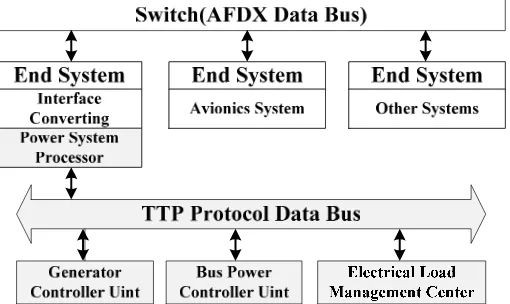
Figure 1 shows the AFDX network and distribution system data exchange diagram, in which the distribution system TTP protocol bus signal and AFDX network through the data conversion interface for message transmission. PSP achieved system control task, received state data from GCU, ELMC and BPCU and received control instruction from avionics systems, comprehensive management of power distribution system [7-10]. The information interaction of system, load power request signal, bus-bar transformation control and relay control instruction etc and so on for important short-frame data; Generator state, battery state and load state of power supply etc and so on for relatively important tasks data; Bus-bar transition state of contactor, relay status, and data backup etc and so on for general tasks data. The important instructions are usually short-frame and require real-time high and low delay. Thus, the network environment is based on the signal of the AFDX network and aircraft distribution system, a new scheduling strategy of terminal system is put forward, which is based on the short-frame prior scheduling and integrated with WRR. The new approach, reduce the delay upper bound of terminal system and improve the system transmission efficiency [11-14].
Figure 1. Data interaction of AFDX network with distribution system
3. Short-Frame Prior with WRR Combined Scheduling
1
BAG 1
max
l
3
BAG 3
max
l
2
BAG 2
max
l
2
3
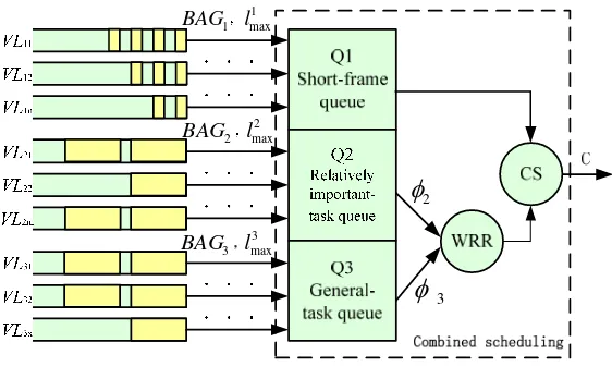
Figure 2. The combined scheduling strategy structure
Combined scheduling structure parameter description:
i
BAG(ms): The parameters of the virtual link, which indicates the bandwidth allocation interval [3, 4];
max i
l (bit): the maximum frame length of the virtual link [3, 4];
1
Q: The highest priority queue, aggregate short-frame data stream -- frame length is less than 100 bytes;
2
Q : The relatively important task, aggregate long-frame data stream -- frame length is longer than 100 bytes;
3
Q : The general task, aggregate long-frame data stream -- frame length is longer than 100 bytes;
2
: The weight ofQ2, show the number of packets inQ2queue is processed in a roundof WRR [4];
3
: The weight ofQ3, show the number of packets inQ3queue is processed in a roundof WRR [4];
2
k , k3: The numbers of packets inQ2,Q3queue transmitted in a round robin of
scheduling [4];
C(Bps): The bandwidth of physical link [3,4];
At a certain time, virtual link come into the combined scheduling server, according to the maximum frame length, arrived VL respectively into the corresponding priority queue (see Figure 1), initialize thatk2=k3=0 , set the value of C.
Step 1: First judge whether the Q1 queue has a data frame to arrive, if so, send the first
packet in the Q1 team, continue to step 1; otherwise jump to the steps 2;
Step 2: Judge whether k2is great than or equal to
2, if so, go to step 3; otherwise sentthe first packet in the Q2 team, k2 k21, continue with step 1;
Step 3: Judge whether k3is great than or equal to
3, if so, k2 k30and go to step 1;otherwise sent the first packet in the Q3 team, k3k31, continue with step 1;
3.1. Service Curve of Short-Frame Queue
schedule and process the short-frame packet, but it will be blocked at more once with the being processed data packets. Therefore, the service curve of short-frame queue is:
2 3
max max
1
8 ( )
( )t C (t max l l )
C
, (1)Where, lmax2 , lmax3 is the maximum frame length of the Q2, Q3queue.
When the highest priority Q1 queue has multiple virtual link data flows, according to the analysis of the FIFO scheduling algorithm, without considering the end system scheduler generates a delay jitter, the service curve for the jth VL data flow in the Q1 queue:
2 3 1
1
max max max max
1
1
( )
8
( ) ( ) ( 8 )
i i
i j
j i j
i
max l l l
l
t C t
BAG C
,
(2)Where, 1 max
i
l is the maximum frame length of the ith VL in Q1 queue, BAG1i is the
bandwidth allocation interval of the ith VL in Q1 queue.
3.2. Service Curves of Relatively Important Task and General Task
According to the combination scheduling strategy, the data flow in the Q2/Q3queue can be processed just when the data stream of the high priority queue has been processed. The first delay corresponding to the situation is the frame is being blocked with the high priority queue, so the sum of the service curves obtained by the important task and the general task queue is:
1
1 max
max 1
2 3 1
1 1 max
1 1 8 8 ( ) ( ) ( ) 8 n i i n i
Q Q n i
i i
i i
l l
t C t
l BAG C BAG
(3)Where, n is the number of virtual link aggregation for the high priority queue.
According to the combined scheduling strategy, the important task and the general task was scheduled by WRR, so the service curves of the Q2, Q3 queue are:
1 3
1 2 max 3 max
max 2 max 1
2 3 1
1 1 max
max
2 1 1
8
( ) ( ) ( 8 )
8 ( ) n i i n i i n m i i m
m i i
l l
l l
t C t
l BAG l C BAG
(4)1 2
1 3 max 2 max
max 3 max 1
3 3 1
1 1 max
max
2 1 1
8
( ) ( ) ( 8 )
8 ( ) n i i n i i n m i i m
m i i
l l
l l
t C t
l BAG l C BAG
(5)When the important task Q2 queue and the general task Q3 queue have multiple virtual
link data flows, the service curves for the jth VL data flow in the Q2, Q3 queue can be get by
1 2 2
max 2 max max
2 3
1 1 2
max 2
2
1 3
max
max 3 max
1
1 1 2
max max 2 max
3
1 1 1 1
max 2
8 8
( ) (( ) )
( )
8 ( )
8 ( )
( ) 8 8 ( ) ( ) i m n j m
i i m j m
m m n m i m j i i i n n m
i i i i
m m
l l l
t C BAG BAG l l l l t
l l l
C C BAG BAG l
1 3 3
max 3 max max
3 3
1 1 3
max 2
3
1 2
max
max 2 max
1
1 1 3
max max 3 max
3
1 1 1 1
max 2
8 8
( ) (( ) )
( )
8 ( )
8 ( )
( ) 8 8 ( ) ( ) i m n j m
i i m j m
m m n m i m j i i i n n m
i i i i
m m
l l l
t C BAG BAG l l l l t
l l l
C C BAG BAG l
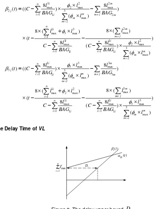
3.3 The Delay Time of VL
( ) i t max 1 n i i l ( ) Qit i D
Figure 3. The delay upper bound Dij
As shown in Figure 2, the arrival curve of all virtual links in different priority queueQican be expressed as:
max max 1
( )
(
)
i n i Qi i il
t
l
t
BAG
(6)From the Figure 3, we know that in order to ensure the real-time and validity when data transmission, the setting of the parameters such as bandwidth and weight ratio guarantees that the service rate of the virtual link is greater than the rate of its arrival.
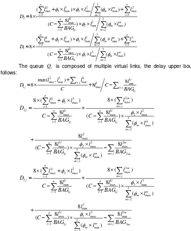
Then, we will calculate the delay upper bound Diof Qiqueue under the combined scheduling algorithm:
2 3 1
1 max max max
1
8 ( ( ) )
n
i
D max l l l C
3
1 3 2 2
max 3 max 2 max max max
1 2 1
2 1 3
2 max
2 max max
1 1 2
( ) ( ) 8 8 ( ) ( ) n n i m m
i m i
i n
m m
i i m
l l l l l
D
l
C l l
BAG
31 2 3 3
max 2 max 3 max max max
1 2 1
3 1 3
3 max
3 max max
1 1 2
( ) ( ) 8 8 ( ) ( ) n n i m m
i m i
i n
m m
i i m
l l l l l
D
l
C l l
BAG
The queue Qi is composed of multiple virtual links, the delay upper bound Dij as follows:
2 3 1
1
max max max 1 max
1 max
1
( ) 8
8 8
i
i i j
j i j
i
max l l l l
D l C
BAG C ,
2 1 3 maxmax 3 max
1
2 1 1 2
max max 2 max
3
1 1 1 1
max 2
2 max
1 2 2
max 2 max max
3
1 1 2
max 2
8 ( )
8 ( )
8 8 ( ) ( ) 8 8 8 ( ) ( ) n m i m j i
j n i n i
m
i i i i
m m
i m
n
m
i i m j m
m m
l
l l
D
l l l
C C
BAG BAG
l
l
l l l
C BAG BAG l
3 1 2 maxmax 2 max
1
3 1 1 3
max max 3 max
3
1 1 1 1
max 2
3 max
1 3 3
max 3 max max
3
1 1 3
max 2
8 ( )
8 ( )
8 8 ( ) ( ) 8 8 8 ( ) ( ) n m i m j i
j n i n i
m
i i i i
m m
i m
n
m
i i m j m
m m
l
l l
D
l l l
C C
BAG BAG
l
l
l l l
C BAG BAG l
The upper expression shows the delay upper bound has some connection with the physical link bandwidth, the maximum frame-length and weight ratio.
4. Combination Scheduling Compared with other Scheduling Algorithms
Taking an AFDX terminal system environment which has more short-frame data as an example (configuration as shown in Table 1, comparative research of maximum delay upper bound of the three scheduling algorithm.
Table 1. Configuration Table of VL
data type num BAGi lmax weight(byte)
Short-frame 12 1ms 100byte
Relatively important task 4 1ms 600byte 5
Calculate the maximum delay upper bound of VL in short-frame prior scheduling strategy [3], WRR scheduling strategy[4] and the combined scheduling strategy, which are listed in table 2.
Compared with the short-frame prior scheduling algorithm, combined scheduling strategy can improve the long time waiting problem of long frame data link, which is resulted from the short frame data, it ensure the full bandwidth of the relatively important task by giving up the bandwidth of general task, and reduce the send time delay.
Compared with the WRR scheduling algorithm, combined scheduling strategy can effectively reduce the maximum delay upper bound of short frame VL. Therefore, it is feasible and applicable to airborne network with more short-frame and different priority data flow and it can effectively improve the network transmission efficiency.
Table 2. The maximum delay upper bound of VL
data type combined(s) Short-frame(s) WRR(s)(60:5:2) Short-frame 160 160 573
Relatively important task 326 836 1004
General task 982 836 1992
5. Simulation Analysis
AFDX network simulation model is established, the simulation research of the virtual link delay time and the data transmission efficiency of the terminal system model under different scheduling algorithm.
5.1. The Terminal System Modeling
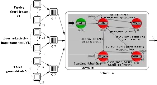
OPNET is network simulation software, which can accurately analyze properties and behavior of complex network [4]. In the OPNET simulation environment, AFDX terminal system is build with different scheduling strategy, as shown in Figure 4. p_1~p_12, p_13~p_16, p_17~p_19 respectively for the source module 12 short-frames, 4 relatively important task and 3 general task link, Q1, Q2, Q3 are 3 high and low priority queue module, Schedule is a scheduling strategy processing module.
Reference to three scheduling strategy processor model in the Schedule module, according to the theoretical calculation results, the superiority and applicability of the combined scheduling can be demonstrated by the simulation results.
Figure 4. The model of AFDX terminal system
5.2. Comparison of Transmission Efficiency
By Figure 5(a), combined scheduling algorithm improved the transmission efficiency of the relatively important task of virtual link, delay time decreased by 16.0%, but for general task virtual link delay time increased by 16.1%, and delay time control within ms level.
By Figure 5(b), combined scheduling algorithm reduced the short-frame link delay time, and each virtual link delay time is less than the maximum delay upper bound, the total delay time decreased by 40.0%, improve the transmission efficiency of AFDX terminal system.
(a) (b)
Figure 5. The VL delay time (s) in both strategy
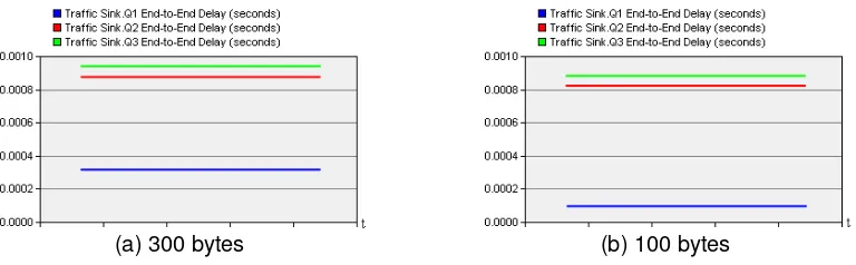
5.3. Effects of Short-Frame Length to Delay Time
For the combined scheduling strategy is proposed in this paper, queue Q2, Q3 weight ratio of 1:1, the author appropriately increase the biggest frame length of short-frame queue, then analyzes the changes of each VL delay time, and the influence on the sum of each VL delay time.
If the biggest frame length of short-frame queue is reduce, the short-frame VL delay time can be further shortened;
The relatively important task and general task queue delay time are also reduce, the sum of delay time decreased and improve the bandwidth utilization;
(a) 300 bytes (b) 100 bytes
Figure 6. The VL delay time in different frame length of short-frame
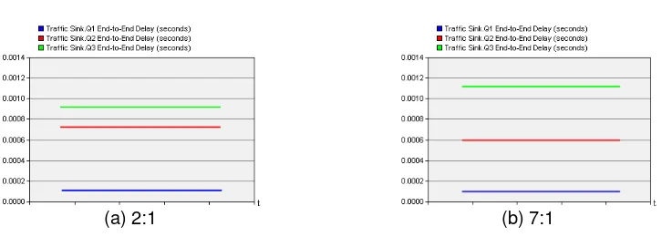
5.4. Effects of Weight Ratio to Delay Time
(a) 2:1 (b) 7:1
Figure 7. The VL delay time in different weight radio
If the weight ratio of the relatively important task queue is increased, the relatively important task VL delay time can be further shortened. However, the delay time of general task VL will increase;
When the send time of general task VL is limited, we should properly increase weight ratio of general task VL;
6. Conclusion
In this paper, we use the network calculus theory, analyze and study the data stream transmission delay of AFDX network terminal system, and give a feasible combination scheduling strategy based on the short-frame prior scheduling with WRR. The strategy prioritizes data flow by the length of frame and mission-critical, short-frame data prior to send, for the relatively important task and general task of low priority tasks data by means of WRR scheduling. Compared with the common other scheduling strategy, the revised strategy reduces the maximum delay upper bound and the delay time of short-frame VL. A VL delay time is reduced and, the system bandwidth utilization was improved. For the combined scheduling strategy, it is feasible and applicable to airborne network with more short-frame and different priority data flow. Still greater efforts are needed before we make the strategy compatible with more complex data flow.
References
[1] Hamilton TW, Melbourne WG. Information content of a signle pass of Doppler data from a distant spacecraft. JPL Space Programs Summary. 2003; 37-39(3): 18-23.
[2] Zhang Yongtao, Huang Zhen, Xiong Huagang. Real time schedu- ling algorithm based on rate-guaranteed in AFDX switch. Journal of Beijing University of Aeronautics and Astronautics. 2010; 36(12): 1412-1416.
[3] Wu Huan, Ge HongJuan, Ni JianLi, Xu Yuanyuan. AFDX end system transmission strategy based on shortest frame first scheduling. Aeronautical Computing Technique. 2012; 42(6): 125-128.
[4] Wei L, Hua LX. The Error Control Methods of Information System in Sensor Networks. Bulletin of Electrical Engineering and Informatics. 2015; 4(3): 210-216.
[5] Hussein Charara, Jean - Luc Scharbarg, Christian Fraboul. Methods for Bounding End-to-end Delays on an AFDX Network. Proceedings of the 18th Euromicro Conference on Real-Time Systems (ECRTS'06). 2006.
[6] Frank I, Ike D, Jimi A, Kayode O. Multiple-Access Technology of Choice In 3GPP LTE. Indonesian Journal of Electrical Engineering and Informatics. 2013; 1(3): 69-77.
[7] Chen Si, Ge Hongjuan, Yang Zonghan, Yang Jingzhong. Research on simulation of communication in Aircraft Power Distribution System based on TTP protocol. Aeronautical Computing Technique. 2014; 44(6): 95-99.
[8] Simatupang JW. Theoretical Analysis on Interferometric Noise in Bidirectional WDM-PON Transmission. Bulletin of Electrical Engineering and Informatics. 2013; 2(1): 45-52.
[9] Yang Xuqiang, Zhi Gaofei. A new generation of avionics bus protocol AFDX. Public Communication of Science & Technology. 2010; (9):194.
[12] Grover A, Grover N. On limits of Wireless Communications in a Fading Environment: a General Parameterization Quantifying Performance in Fading Channel. Indonesian Journal of Electrical Engineering and Informatics. 2014; 2(3): 125-131.
[13] Wang Jianyu, Wang Shikui. Research and design of test method of AFDX switch policing function. Measurement & Control Technology. 2012; 31(7): 82-84.