i
DATA AND SIGNAL ACQUISITION SYSTEM
SREETHARAN A/L SEKARAN
This report is submitted in partial fulfillment of the requirements for the award of Bachelor of Electronic Engineering and Computer Engineering with Honours
Faculty of Electronic and Computer Engineering Universiti Teknikal Malaysia Melaka
ii
“I hereby declare that this report is the result of my own work except for quotes as cited in the references.”
iii
“I hereby declare that I have read this report and in my opinion this report is sufficient in terms of the scope and quality for the award of Bachelor of Electronic
Engineering and Computer Engineering With Honours.”
Signature : ………..
Supervisor’s Name : ………..
iv
v
ACKNOWLEDGEMENT
First and foremost, I would like to convey my deepest appreciation to my supervisor Mr. David Yap Fook Weng for his patience, concern, invaluable guidance and also encouragement throughout the preparation of this thesis.
Besides that, I would like to dedicated my deepest thank to my beloved parents and family members for their tolerance, financial and moral support while completing my tertiary education here. Thanks to all the lecturers, friends, fellow course mate for their pleasure opinion and encouragement.
vi
ABSTRACT
Data and signal acquisition system used to collect information to document or analyze some phenomenon. The data collected may vary in different forms such as waveforms and power line-carrier. Although the data acquisition is very important in this modern world but it is very hard to collect and analyze different type of data in a single data and signal acquisition system and demonstrate it in an appropriate visual. Hence, a data and signal acquisition system is developed in this final year project that can display the data collected in Graphical User Interface (GUI).
The objectives of this project are to receive the data and transmit it to PC by using Bluetooth module. In this project, the Bluetooth module plays the main role to receive the data from the PIC and transmit it to PC. Besides that, a PIC16F877A was used as the ADC to converts the analog signal to digital and send the data to Bluetooth module. While the data transmitted using Bluetooth module will be monitored in PC using GUI.
vii
ABSTRAK
‘Data and signal acquisition system’ digunakan untuk mengumpul untuk mendokumenkan atau menganalisis beberapa fenomena. Data yang dikumpul mungkin berbeza dari segi bentuk, contohnya gelombang dan isyarat elektrik. Walaupun ‘Data and signal acquisition system’ penting di zaman moden ini, ia adalah susah untuk mengumpul dan menganalisis pelbagai jenis data dan isyarat dalam satu sistem dan mempamerkan dalam gambaran. Oleh itu, demi menyelesaikan masalah ini, satu ‘data and signal acquisition system’ yang mempamerkan data dan isyarat yang dikumpul dalam ‘Graphical User Interface (GUI)’.
viii
TABLE OF CONTENTS
CHAPTER CONTENT PAGE
PROJECT TITLE i
DECLARATION ii
DEDICATION iv
ACKNOWLEDGEMENT v
ABSTRACT vi
ABSTRAK vii
TABLE OF CONTENTS viii
LIST OF TABLES xiii
LIST OF FIGURES xiv
LIST OF APPENDIX xvi
LIST OF ABBREVIATIONS xvii
I INTRODUCTION TO PROJECT
1.1 Introduction 1
1.2 Objectives 2
1.3 Problem Statement 2
1.4 Scopes 3
1.5 Content Overview 3
ix II LITERATURE REVIEW
2.1 Introduction 5
2.2 Data Acquisition 5
2.2.1 Data Acquisition System 6 2.2.2 The Way Data is Acquired 7
2.2.3 Data Logging System 9
2.2.4 Types of Data Logger 10
2.2.4.1 Mechanical Data Logger 10 2.2.4.2 Electronic Data Logger 11 2.2.4.3 Wireless Data Logger 12 2.3 Wireless Data Acquisition System 12 2.3.1 Types of Wireless Data Acquisition System 13
2.3.1.1 Wireless Data Acquisition System using Bluetooth Module 13 2.3.1.2 Wireless Data Acquisition System
using RF 14
2.3.2 Bluetooth Technology 16
2.3.3 Bluetooth Profiles 18
2.3.4 Bluetooth Specification and Features 20 2.3.5 The Future of the Bluetooth 23 2.3.6 The Advantages and Disadvantages
of Bluetooth 24
2.3.6.1 Advantages of Bluetooth 24 2.3.6.2 Disadvantages of Bluetooth 25
2.3.7 How Bluetooth Works 25
2.3.7.1 Frequency Hopping 26
2.3.8 Bluetooth Application 28
2.4 Programmable Intelligence Computer 28
2.4.1 History of PIC 29
x 2.4.2.4 PIC18 High End Core Devices 34
2.4.2.5 PIC24 and dsPIC 16-bit
Microcontrollers 35 2.4.2.6 PIC32MX 32-bit Microcontrollers 36
2.4.3 Device Programmer 36
2.4.4 16F877A PIC 38
2.4.5 Writing Program 40
2.5 LabVIEW 40
2.5.1 Dataflow Programming 40
2.5.2 Graphical Programming 41
2.5.3 Benefits of LabVIEW 42
III METHODOLOGY
3.1 Project Methodology 45
3.1.1 Hardware Development 45
3.1.2 Software Development 46
3.1.2.1 Graphical User Interface (GUI) 46
3.1.2.2 GUI Design 47
3.1.3 Communication between Software and
Hardware 49
3.1.4 Interface between PIC and PC using
Bluetooth module 49
3.1.5 Experimental Testing 50
IV PRELIMINARY RESULT
4.1 Project Preliminary Result 51
4.1.1 Connection between Bluetooth Module
and PIC 16F877A 52
xi
4.2 Expected Results 55
V PROJECT DESCRIPTION
5.1 Introduction 56
5.2 Design Requirements 57
5.3 Planning 58
5.4 Design Consideration 58
VI PROJECT PROCESS FLOW
6.1 Introduction 60
6.2 Process Flow of the Circuit Design 61 6.3 Process Flow of the LabVIEW 63 6.4 Process Flow of the PIC burning 65 6.5 Process Flow of the Bluetooth Functionality
Test 68
VII RESULT AND DISCUSSION
7.1 Introduction 71
7.2 Programming Coding 71
7.3 Circuit Construction 74
7.4 Hardware Construction 75
7.5 ADC Conversion 77
7.6 GUI Designing 78
xii VIII CONCLUSION AND RECOMMENDATION
8.1 Conclusion 84
8.2 Recommendation 85
xiii
LIST OF TABLE
NO TITLE PAGE
2.1 12 Bit Instruction Set 31
xiv
LIST OF FIGURE
NO TITLE PAGE
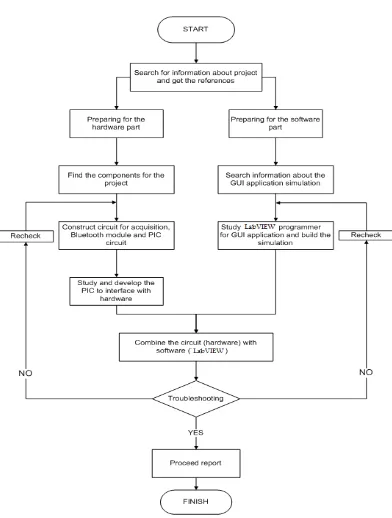
1.1 Flowchart of methodologies used in this project 4
2.1 Mechanical Data Logger 11
2.2 Electronic Data Logger 11
2.3 Wireless Data Logger 12
2.4 RF Data Acquisition System 15
2.5 Bluetooth Connectivity 18
2.6 Flowchart for Bluetooth Communication Link 27 2.7 Various older (EPROM) PIC microcontrollers 30
2.8 PIC 16F877A Pinout 38
2.9 Block Diagram of PIC16F877A 39
2.10 LabVIEW Logo 40
3.1 The Getting Started window 47
3.2 The Front panel and Block diagram windows 48
3.3 GUI designed 49
4.1 The Connection between Bluetooth Module and PIC 16F877A 52
4.2 GUI designed 53
4.3 ADC Simulation Circuit 54
4.4 ADC Simulation Source Code 54
5.1 Sketch of the Design 59
6.1 New Design Page 61
6.2 Pick Device Window 61
6.3 Circuit designed 62
xv
6.5 Simulation Output 63
6.6 Blank VI 63
6.7 Tool Box 64
6.8 Block Diagram 64
6.9 Front Panel 65
6.10 PIC Burner 65
6.11 The .hex file selected 66
6.12 The .hex file is loaded into PIC 66
6.13 The PIC is programmed 67
6.14 The program is verified 67
6.15 The program is read and justified 68
6.16 The USB cable connection 68
6.17 The Hyper Terminal Window 69
6.18 The Comp port properties window 69
6.19 AT response from KC Wirefree Bluetooth transceiver 70
7.1 Circuit Construction 74
7.2 Reset Button 75
7.3 Complete Project 76
7.4 Interior View 76
7.5 Top View 77
7.6 ADC Conversion 77
7.7 Virtual Output 78
7.8 GUI designed 78
7.9 Block Diagram of read .lvm file 79
7.10 GUI of read .lvm file 79
7.11 Sample sine wave received with amplitude =1, frequency =1kHz 80 7.12 Sample square wave received with amplitude =1,
frequency =100Hz 80
xvi
LIST OF APPENDIX
NO TITLE PAGE
A1 ISKIM PIC 88
B1 KC Wirefree Bluetooth User Manual 91
xvii
LIST OF ABBREVIATIONS
PIC - Peripheral Interface Controller PSM - Project Sarjana Muda
DSP - Digital Signal Processing ADC - Analog to Digital Convertor DAC - Digital to Analog Convertor
I/O - Input or Output
GUI - Graphical User Interface
VB - Visual Basic
PC - Personal Computer
CPU - Central Processing Unit
UART - Universal Asynchronous Receiver Transmitter EPROM - Erasable Programmable Read Only Memory ICSP - In Circuit Serial Programming
LVP - Low Voltage Programming MAC - Multiply Accumulate
RAM - Random Access Memory
1
CHAPTER 1
INTRODUCTION TO PROJECT
1.1 Introduction
Wireless system is the transfer of information over a distance without the use of electrical conductors or wire. The distances involved may be short as few meters in television remote control or very long as thousands or even millions of kilometers in radio communications. Bluetooth also included in the wireless system category in term of the information transfer.
Bluetooth is a wireless protocol utilizing short-range communications technology facilitating data transmission over short distances from fixed and/or mobile devices, creating wireless personal area networks (PANs). Bluetooth uses a radio technology called frequency hopping spread spectrum. It chops up the data being sent and transmits chunks of it on up to 75 different frequencies. [8] (Adam Prybil. 2002)
2 signal and monitored in PC using graphical user interface, developed using Visual Basic. The main aim of this project is to provide a suitable interfacing system that can monitor the data and signal using Bluetooth module.
1.2 Objectives
Following are the objectives set in this project:
• To study the characteristic of Programmable Intelligence Computer, PIC and the control system for the Bluetooth module.
• To develop a suitable PIC circuit diagram simulation to transfer the data from the signal generator to the computer. Several circuit diagram will designed and tested before the best circuit diagram is selected.
• To develop the model of the control system based on the PIC circuit diagram selection result.
• To develop a user-friendly GUI interface design
1.3 Problem Statement
3 1.4 Scopes
The scopes of the project are as follow:
1. Study on PIC16F877A to send data and signal to PC.
2. The control system is design specially to produce a user friendly GUI interface and able to receive data from the power line using the Bluetooth module and transfer the data into the GUI interface.
3. Development will be carried out until working model stage.
4. Use of IVT BlueSolei Software to interface the Bluetooth module with computer.
5. This project focuses on development of a PIC circuit diagram. 6. Use of LabVIEW to build graphical user interface (GUI) in PC.
7. Signal from function generator to test the system, Amplitude = ±10V and Frequency = 0 – 3000Hz.
8. Focus on low frequency range and not on high frequency. 9. Data transmitted: 800 bit/sec.
1.5 Content Overview
4 1.5.1 Work Flow Description
5
CHAPTER 2
LITERATURE REVIEW
2.1 Introduction
A literature search was performed to study, design and analysis the wireless data and signal acquisition system. It also includes the investigation of what others have done in this area. This study included the areas of electric, electronic and BlueSolei software as a guide to design the circuit for the retractor.
2.2 Data Acquisition
6 Acquired data are displayed, analyzed, and stored on a computer, either using vendor supplied software, or custom displays and control can be developed using various general purpose programming languages such as BASIC, C, Fortran, Java, Lisp, Pascal. While the specialized programming languages used for data acquisition include, EPICS used to build large scale data acquisition systems, LabVIEW, which offers a graphical programming environment optimized for data acquisition and MATLAB provides a programming language but also built-in graphical tools and libraries for data acquisition and analysis. (W. R. Leo, 1994)
2.2.1 Data Acquisition System
7 2.2.2 The Way Data is Acquired
Data acquisition begins with the physical phenomenon or physical property of an object to be measured. This physical property or phenomenon could be the temperature or temperature change of a room, the intensity or intensity change of a light source, the pressure inside a chamber, the force applied to an object, or many other things. An effective data acquisition system can measure all of these different properties or phenomena.
A transducer is a device that converts a physical property or phenomenon into a corresponding measurable electrical signal, such as voltage, current, change in resistance or capacitor values, etc. The ability of a data acquisition system to measure different phenomena depends on the transducers to convert the physical phenomena into signals measurable by the data acquisition hardware. Transducers are synonymous with sensors in DAQ systems. There are specific transducers for many different applications, such as measuring temperature, pressure, or fluid flow. DAQ also deploy various Signal Conditioning techniques to adequately modify various different electrical signals into voltage that can then be digitized using ADCs.
Signals may be digital or analog depending on the transducer used. Signal conditioning may be necessary if the signal from the transducer is not suitable for the DAQ hardware to be used. The signal may be amplified or deamplified, or may require filtering, or a lock-in amplifier is included to perform demodulation. Various other examples of signal conditioning might be bridge completion, providing current or voltage excitation to the sensor, isolation, linearization, etc.