I/ we admit that have read this work and in my opinion / we this work was adequate from the aspect scope and quality to the meaning Bachelor of Mechanical
Engineering (Thermal Fluids) Degree Programme
Signature : ………...
Supervisor Name 1 : ……….
TOUGHNESS OF FIBREGLASS LAMINATED COMPOSITES
KAM PEI YI
This report is presented in
partial fulfilment of the requirements for the
Degree of Bachelor of Mechanical Engineering (Thermal Fluid)
Faculty of Mechanical Engineering Universiti Teknikal Malaysia Melaka
ii
“I hereby, declare this thesis is result of my own research except as cited in the references”
Signature : ………...
Author’s Name : KAM PEI YI
iii
iv
ACKNOWLEDGEMENTS
Firstly, I would like to express my greatest gratitude and appreciation to my supervisor of this Project Sarjana Muda, En. Kamarul Ariffin Zakaria for his care, guidance, unparalleled support and useful yet practical advices throughout the entire project.
Special thanks to the Faculty of Mechanical Engineering, Universiti Teknologi Malaysia Melaka (UTeM) for the opportunities given and facilities offered. In addition, I also would wish to thank Mr. Hisham, Mr.Azahar, Mr.Khairil, Mr. Mazlan, and other lab assistants whose help and careful guidance had contributed towards the success of this research.
v
ABSTRACT
vi
ABSTRAK
vii
TABLE OF CONTENTS
CHAPTER CONTENTS PAGES
VERIFICATION ii
DEDICATION iii
ACKNOWLEDGEMENT iv
ABSTRACT v
ABSTRAK vi
TABLE OF CONTENTS vii
LIST OF FIGURE xi
LIST OF TABLE xvii
LIST OF APPENDIX xix
CHAPTER I INTRODUCTION
1.1 Background 1
1.2 Objective 2
1.3 Scope 2
1.4 Problem Statement 3
1.5 Report Overview 3
CHAPTER II LITERATURE REVIEW
2.1 Composite Materials 4
viii
CHAPTER CONTENT PAGES
2.2.1 Fibre Types 5
2.2.2 Fibre Forms 7
2.3 Matrix Materials 9
2.3.1 Polymeric Matrix 10
2.3.1.1 Thermoset Matrices 10 2.3.1.2 Thermoplastic Matrices 12
2.3.2 Metal Matrix 12
2.3.3 Ceramic Matrix 12
2.4 Definition of Lamina and Laminate 13
2.4.1 Laminate Description 14
2.5 Properties of Composite Material 14
2.5.1 Orthotropic Material 16
2.5.2 Heterogeneous, Homogeneous, Isotropic and Anisotropic Material 17
2.6 Typical Properties of Composite Material 17
2.6.1 Toughness 19
2.7 Fabrication of Fibreglass Laminated
Composite 19
2.7.1 Hand Lay-Up 20
2.7.2 Filament Winding 22
2.7.3 Compression Molding 23
2.7.4 Resin Transfer Molding (RTM) 23
2.7.5 Pultrusion 24
ix
CHAPTER CONTENT PAGES
CHAPTER III METHODOLOGY
3.1 Introduction 26
3.2 Preparation of Sample Test 27 3.2.1 Material properties 28
3.2.2 Apparatus 29
3.2.3 Procedure 29
3.3 Exposed to Environment 36
3.4 Charpy Test 39
3.4.1 Procedure 40
CHAPTER IV RESULTS
4.1 Results for Charpy test under
varying temperature 43
4.2 Results for Charpy test under
different solution 47
4.3 Results for Charpy test under
different orientation and resin 50
CHAPTER V DISCUSSION
5.1 Effect of testing temperature
on impact energy 53
5.1.1 Temperature 27˚C -55˚C 54
5.1.2 UV light 57
5.2 The effect of immersion in solution
on impact energy 58
x
CHAPTER CONTENT PAGES
5.2.3 Distilled water and River water 62
5.2.4 Sea water 63
5.3 Effect of difference resin and
orientation on impact energy 65
CHAPTER VI CONCLUSION 68
REFERENCES 70
xi
LIST OF FIGURE
NO TITLE PAGES
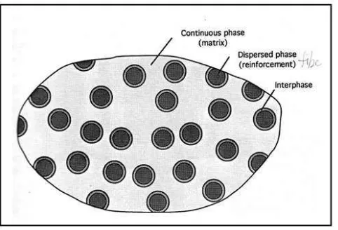
2.1 Phases of a Composite Material 4
(Source: Daniel and Ishai, (1994))
2.2 Classification of Fibre Form 8
(Source: Daniel and Ishai, (1994))
2.3 Unidirectional lamina and principal coordinate
Axes 13
(Sources: Daniel and Ishai, (1994))
2.4 Multidirectional laminate and reference
Coordinate System 14
(Sources: Daniel and Ishai, (1994))
2.5 Level of observation and types of analysis for
Composite materials 15
(Sources: Daniel and Ishai, (1994))
2.6 An orthotropic material has three planes
of symmetry 16
xii
NO TITLE PAGES
2.7 Hand lay-up 21
(Sources: Barbero, E.J., (1998))
2.8 Filament winding 22
(Sources: Barbero, E.J., (1998))
2.9 Compression molding 23
(Sources: Barbero, E.J., (1998))
2.10 Resin transfer molding 24
(Sources: Barbero, E.J., (1998))
2.11 Pultrusion 25
(Sources: Barbero, E.J., (1998))
2.12 Vacuum Bag Molding 25
(Sources: Barbero, E.J., (1998))
3.1 Woven roving glass fibre [45/45] and [0/90] 28
3.2 Epoxy resin, polyester resin and hardener 28
3.3 Apparatus and proper wearing 29
3.4 Woven roving E-glass in roll 30
3.5 Cutting unrolled E-glass 31
xiii
NO TITLE PAGES
3.7 Resin prepared 32
3.8 Resin catalysed by hardeners 32
3.9 Stir the mixture 32
3.10 Wet out the surface of mould 33
3.11 Brush was used to wet out E-glass 33
3.12 Roller used to remove air trapped 34
3.13 Rolled out manually each new layer have
been added 34
3.14 Curing process 34
3.15 Milling and facing process to prepare v-notch 35
3.16 The standard dimension of an impact test specimen
(Sources: Khalid, A.A, (2004)) 36
3.17 Soak in distill water 37
3.18 Soak in alkaline solution 38
xiv
NO TITLE PAGES
3.21 Soak in acid solution 38
3.22 Specimens in oven 39
3.23 Pendulum impact tester machine MH 365 40
3.24 Turn hand-wheel in anti-clockwise direction 41
3.25 V-notch specimens across the Charpy parallel jaw 41
3.26 Rise to maximum height, 120˚ 41
3.27 The pendulum strikes opposite the notch 42
3.28 Data collected from digital meter 42
4.1 Sample of fracture glass/polyester at 27˚C 45
4.2 Sample of fracture glass/polyester at 35˚C 45
4.3 Sample of fracture glass/polyester at 45˚C 46
4.4 Sample of fracture glass/polyester at 55˚C 46
4.5 Sample of fracture glass/polyester at UV light 47
4.6 Sample of fracture glass/polyester at acid solution 48
xv
NO TITLE PAGES
4.8 Sample of fracture glass/polyester at river water 49
4.9 Sample of fracture glass/polyester at sea water 50
4.10 Sample of fracture glass/polyester at alkaline solution 50
4.11 Sample of fracture glass fibre [45/45] /polyester
at room temperature 52
4.12 Sample of fracture glass fibre [0/90] /epoxy
at room temperature 52
4.13 Sample of fracture glass fibre [45/45] /epoxy
at room temperature 52
5.1 Impact energy versus testing temperature 54
5.2 Samples under different testing temperature 56
5.3 Impact Energy versus different environment condition 58
5.4 Samples under different immersion solution 60
5.5 Charpy impact energy versus glass/polyester and glass/epoxy with different orientation
under room temperature 65
xvi
NO TITLE PAGES
5.7 Damage modes in composite laminate from impact event
xvii
LIST OF TABLE
NO TITLE PAGES
2.1 Properties of Typical Unidirectional
Composite Materials 18
(Sources: Daniel and Ishai, (1994))
2.2 Advantages and disadvantages of the
Hand lay-up process 21
(Sources: Barbero, E.J., (1998))
2.3 Applications of hand lay-up 21
(Sources: Barbero, E.J., (1998))
3.1 Flow chart of methodology 26
3.2 Condition and pH values for the tested specimens 37
4.1 Results for glass [0/90] / polyester at varying temperature 44
4.2 Results for Charpy impact energy (Ec) against
testing temperature 44
xviii
NO TITLE PAGES
4.4 Results for charpy impact energy (Ec) against
different solution 48
4.5 Results of glass/polyester and glass/epoxy with
different orientation tested under room temperature 51
4.6 Results for Charpy impact energy (Ec) against
xix
LIST OF APPENDIX
NO TITLE PAGES
A Gantt Chart 73
B General Properties for polyester, Epoxy/E-glass 74 C Standard Test Methods for Notched Bar Impact
Testing of Metallic Materials 80
D Results data for Universal Impact Tester 97
1
CHAPTER I
INTRODUCTION
1.1 Background
According to the current global market, conventional structural materials such as steel and aluminium in construction, automotive, aerospace industries and other fields were widely replaced by the usage of fiber reinforced polymers. This overwhelming demand of application is attributed to the high strength-to-weight ratio of the polymer composites, better mechanical properties and ease of handling.
2
Polymer composites are increasingly being used in a wide range of applications where long-term service in hostile environment is required. The competitive quality and good mechanical properties of glass fibers has led them to widespread use in reinforced polymer composites. However, composite are prone to degrade when they are exposed to certain environment conditions. Therefore, it is crucial that polymer composite materials be able to retain their mechanical properties and show minimum degradation in this environment (Bagherpour et al. 2008).
1.2 Objective
The main objective in this research is to study the toughness of fiberglass laminated composite under different environment conditions. In addition, it includes the study of type and properties of laminated composites and their manufacturing process.
1.3 Scope
3
1.4 Problem statement
Fiberglass laminated composite are widely used in application due to their low cost and easy to fabricate especially using hand lay-up technique. However, according to Bagherpour et al. (2008), the lack of resistance of composite structures to degradation agents often becomes apparent within a short period of exposure. In some circumstances, only a few hours of exposure may lead to catastrophic failure or seriously damaging structural integrity. Irreversible property changes in polymer matrix composites can be induced by any number of degradation agents such as UV light, water, humidity, alkaline and acid steam environments. Hence, it is necessary to further understand the effect of environment on composites toughness.
1.5 Report Overview
In this report, it contains 6 chapters. In chapter 1, it is about the description of the background of composite materials, the objectives and scope of this research and the problem statement that lead us to conduct the experiment.
4
CHAPTER II
LITERATURE REVIEW
2.1 Composite Materials
[image:24.612.200.441.508.672.2]Composite materials are formed by the combination of two or more materials to achieve properties (physical, chemical, etc.) that are superior to those of the constituents (Barbero 1998). The main components of composite materials are fibers and matrix. Daniel and Ishai (1994) explained that one of the phases is usually discontinuous, stiffer, and stronger and is called reinforcement, whereas the less stiff and weaker phase which continuous is called matrix. Sometimes, because of chemical interactions or other processing effects, an additional phase, called interphase, exist between the reinforcement and the matrix as shown in Figure 2.1.