i
‘I hereby declare that I have read this dissertation and found its content and form to meet acceptable presentation standards of scholarly work for the award of
Bachelor of Mechanical Engineering (Thermal-Fluid)’
Signature :
Name of Supervisor I :
ii
Air flow distribution of a fan using CFD method
NASRUL HAKIM BIN KHALID
A report submitted in partial fulfillment of the
Requirement for the award of the degree of
Bachelor of Mechanical Engineering (Thermal-Fluid)
Faculty of Mechanical Engineering
Universiti Teknikal Malaysia Melaka
iii
I declare that this thesis entitled “Air flow distribution of a fan using CFD method” is the result of my own research except as cited in the references.
iv
v
ACKNOWLEDGEMENT
Alhamdulillah, all praise to Allah, the Most Beneficent and the Most Merciful, who has taught what I knew or not. It is by the grace of the Almighty Allah that this project has been completed successfully.
A deepest appreciation is dedicated to Mr. Shamsul Bahari Bin Azraai as my project supervisor for his extraordinary patience and his enduring optimism. I really admire his knowledge, intelligence and patience. I do appreciate his dedicated guidance, suggestion, critical comments and warm support which have given me the opportunity to develop my project skills. It would have been very difficult to complete this project without the enthusiastic support, insight and advice given by him.
To all my friends or people, who directly or indirectly contribute to this project, I thank all of you for your encouragement, continued support and friendship.
vi
ABSTRACT
vii
ABSTRAK
viii
TABLE OF CONTENTS
CHAPTER TITLE PAGE
DECLARATION i
DEDICATION iv
ACKNOWLEDGEMENT v
ABSTRACT vi
ABSTRAK vii
TABLE OF CONTENTS viii
LIST OF TABLES xi
LIST OF FIGURES xii
LIST OF APPENDICES xv
LIST OF SYMBOLS xvi
LIST OF ABBREVIATIONS xvii
1. INTRODUCTION 1
1.1 Project background 1
1.2 Problem Statement 2
1.3 Objective of the Project 3
1.4 Scope of the Project 3
2. LITERATURE REVIEW 5
2.1 Introduction 5
2.1. Previous Research 5
2.3 Axial fan Geometry 8
ix
2.3.2 The Fan Curve 12
2.4 CFD Analysis 16
2.4.1 Pre-processor 16
2.4.2 Solver 17
3. METHODOLOGY 18
3.1 Introduction 18
3.2 Numerical CFD Model 20
3.3 Design Process 20
3.4 CFD Analysis 23
3.4.1 Convert File from 23
SolidWorks 2008 to ACIS
3.4.2 Mesh Procedure 24
3.5 The FLUENT 6.3.16 Simulations 25
4. RESULTS AND DICUSSIONS 26
4.1 Introduction 26
4.2 Computational Fluid Dynamic 26
Simulation Results for Velocity Profile
4.3 Computational Fluid Dynamic 28
Simulation Results for Volume Flow Rate
4.4 Computational Fluid Dynamic 30
Simulation Results for Pressure
4.5 Simulation Discussion 31
4.6 Velocity Profile 32
5.2.1 Presence of two flow region 33
x
5. CONCLUSIONS AND 36
RECOMMENDATION
REFERENCE 37
BIBLIOGRAPHY 38
xi
LIST OF TABLES
No. TITLE PAGE
3.1 Geometry design of the fan for this project 20
4.1 Data for velocity at speed 5m/s 26
4.2 Data for and velocity properties at speed 10 m/s 27
4.3 Data for Volume flow rate at speed 5m/s and 10m/s 28
xii
LIST OF FIGURES
No. TITLE PAGE
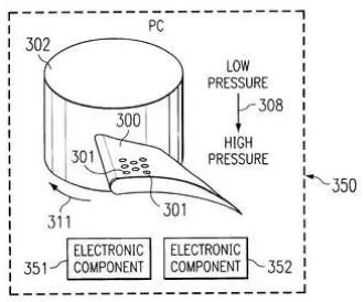
1.1 The pressure distribution through fan blade. 2 (Source: http://www.freepatentsonline.com)
2.1 Static pressure and power consumption 6
versus blade angle.
(Source: Seyedsharif Khoshmanesh.2009)
2.2 Flow rate vs. blade angle for different models 7 of fans.
(Source: Seyedsharif Khoshmanesh.2009)
2.3 Efficiency vs. blade angle for different models 8 of fans.
(Source: Seyedsharif Khoshmanesh.2009)
2.4 Axial Fan with 5 blades. 9
(Source:http://img.alibaba.com/photo/ 232009159/Axial_fan_blades_5_blades_ evaporative_cooler_parts.summ.jpg)
2.5 Air Flow of Aerodynamics . 9
(Source: http://encarta.msn.com)
xiii
(Source: Mike Turner.2003)
2.7 Dynamic viewpoint of a particle. 11
(Source: http://encarta.msn.com)
2.8 Fan/system interaction 12
(Source: Mike Turner.2003)
2.9 Deflection angle at blade surface 13
(Source: http://www. axial_fan_stall.html)
2.10 Bernoulli’s law 14
(Source: http://www. axial_fan_stall.html)
2.11 Flow across an axial flow blade. 15
(Source: Keith Sherwin & Michael Horsley, 1996)
3.1 Electrical household fan 18
3.2 Flow Chart 19
3.3 Blade geometry 21
3.4 Fan core geometry 21
3.5 Complete fan geometry 22
3.6 Dimensional duct fan geometry 22
4.1 Graph of comparison velocity outlet 27
at different speed
xiv
blade angle at speed 5m/s
4.3 Graph of Static pressure at different 31
blade angle at speed 5m/s
4.4 The velocity profile for upstream 33
and downstream velocity pressure
4.5 Upstream view 34
4.6 Downstream view 34
4.11 Contour of static pressure with 5 m/s 35
xv
LIST OF APPENDICES
No. TITLE PAGE
1. APPENDICES A 40
2. APPENDICES B 41
xvi
LIST OF SYMBOLS
= specific heat of air, J/kg.K
= mass flow rate of air, kg/s
∆T = desired air temperature differential (cabinet to ambient outside air), K
o
= Degree
Q = air flow rate, m3/s
= angular velocity
= radius
= angle
= Initial velocity
Pa = Pascal
xvii
LIST OF ABBREVIATIONS
CFD = Computational Fluid Dynamic
2D = Second Dimensions
3D = Third Dimensions
1
CHAPTER I
INTRODUCTION
1.1 Project Background
A fan is an apparatus that converts electric energy into aerodynamic energy. Some of this energy is useful to other output energy is wasted energy like the air swirl at the fan exit. The fan was basically a blade attached to an electric motor. Mechanically, a fan can be any revolving vane or vanes used for producing currents of air. Fans produce air flows with high volume and low pressure, as opposed to a gas compressor which produces high pressures at a comparatively low volume. A fan blade will often rotate when exposed to an air stream, and devices that take advantage of this, such as anemometers and wind turbines often have designs similar to that of a fan. Using fans to force air having the proper temperature and relative humidity through a crop is a valuable technique for maintaining quality after harvest. The air helps maintain the moisture, temperature, and oxygen content of a crop at levels that prevent growth of harmful bacteria and fungi and excessive shrinkage.
The aerodynamics of fan does not lend itself readily to mathematical analysis and there are no straightforward methods to predicting the air flow around the fan. The aerodynamic of fan research is very important due to promote optimum efficiency. The constant air flows are needed for greater fan performance and reduction in wind noise level.
2
stable point of operation. If peak efficiency coincides with the peak of the pressure curve then there may be operational problems as volumetric flow rates vary with small changes in system pressure. The designer must consider both curves when selecting the best fan and operating point to optimize reliability and power usage. And fan type may dictate proper selection. Airfoil wheels, while more efficient, may not be a good choice when handling particulate-laden air.
(Gerry Lanham. There's Gold in the Air Power Equation. Retrieved
September 10, 2009 from http://www.mfrtech.com/articles/2289.html).
1.2 Problem Statement
[image:19.595.238.403.575.712.2]Identifying the cause of a fan problem can be difficult due to the wide range of fans and applications as well as the operating points for fans. An air moving device operable to generate a flow of air from a low pressure region to a high pressure region comprising at least one blade operable to generate said flow of air as a result of movement of said at least one blade, wherein said at least one blade includes a rough surface on a side facing said low pressure region and wherein said rough surface is arranged to induce a turbulent boundary layer that enables operation of said air moving device in a manner that would otherwise result in separation of air from said at least one blade. Fan delivers air in an overall direction that is parallel to the fan blade axis.
3
Fan problems generally fall into two categories which there are mechanical or air performance problems. To solve these problems, an extensive unsteady aerodynamic study is in high demand. Because the fan efficiency and corresponding loading are caused by an aerodynamic behavior which relates to the fan performance, the underlying fluid dynamics must be well understood to accurately determine the geometry and to improve fan efficiency. In order to get the optimum efficiency of a fan air flow rate the design of louvered angle of a blade are important because this part can make difference performance on axial fan. To solve these problems, an extensive unsteady aerodynamic study is in high demand. Because the fan efficiency and corresponding loading are caused by an aerodynamic behavior which relates to the fan performance, the underlying fluid dynamics must be well understood to accurately determine the geometry of blade and to improve fan efficiency
1.3 Objective of the project
The objective of this project was to determine the air flow rate at different angle of blade.
1.4 Scope of the project
The scope for this project includes:
4
ii. To construct the CFD fan geometry-design fan blade consist louvered angle.
iii. To simulate numerically air flow through the louvered angle-collect result and data to observe simulation of air flow
5
CHAPTER 2
LITERATURE REVIEW
2.1 Introduction
Literature review is about to understand the theory of the research. The literature review is very important part to understand first in any research. Since we know the theory of the research, we can proceed it easily. It is will be easy to determine the way of the research will be implementing and also the related theory that has used in previous research. The information about the research can be found through the journal, internet, thesis and reference books. In this research case, all the information and theory that related to the fan performance are needed. In this chapter will discuss about previous research about fan performance.
2.2 Previous Research
6
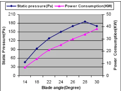
[image:23.595.198.440.358.539.2]comparing these energy losses with cascade test result of Hawell [1] (1942). According to Seyedsharif Khoshmanesh (2009), to check the blade load a complete field run test have been done on the fans. The blade angle has been adjusted to an angle of approximately half that called out on the specification or measured on the unit. The draft gauge is connected to as quiescent a spot in the plenum as possible, preferably in the corner of the plenum ahead of the fan. The fans are start and recorded on the chart provided the blade angle and the static pressure indicated. The blade angle is advanced by one or two degrees and these data are recorded again. The blade angle is increased and followed the procedure until the motor is fully loaded. Figure 1 shows the blade angle versus static pressure and power consumption. It will be noted that the static pressure will be consistently increasing with increased blade angle until the blade loading reaches maximum according to Seyedsharif Khoshmanesh (2009) research.
Figure 2.1: Static pressure and power consumption versus blade angle. (Source: Seyedsharif Khoshmanesh .2009)
7
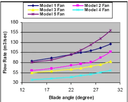
[image:24.595.207.432.152.331.2]stalling flow while the power consumption increase the increasing rate of the flow decrease and even in some point stop and remain fixed so it causes to reduce the efficiency in stalling flow.
Figure 2.2: Flow rate vs. blade angle for different models of fans. (Source: Seyedsharif Khoshmanesh.2009)