i
SMART CAR PARK SYSTEM
TAN LIN WENG
This Report Is Submitted In Partial Fulfillment of Requirements For The Bachelor Degree of Electronic Engineering (Industrial Electronic)
Fakulti Kejuruteraan Elektronik dan Kejuruteraan Komputer Universiti Teknikal Malaysia Melaka
ii
UNIVERSTI TEKNIKAL MALAYSIA MELAKA
FAKULTI KEJURUTERAAN ELEKTRONIK DAN KEJURUTERAAN KOMPUTER
BORANG PENGESAHAN STATUS LAPORAN
PROJEK SARJANA MUDA II
Tajuk Projek : SMART CAR PARK SYSTEM
Sesi Pengajian :
Saya TAN LIN WENG mengaku membenarkan Laporan Projek Sarjana Muda ini disimpan di Perpustakaan dengan syarat-syarat kegunaan seperti berikut:
1. Laporan adalah hakmilik Universiti Teknikal Malaysia Melaka.
2. Perpustakaan dibenarkan membuat salinan untuk tujuan pengajian sahaja.
3. Perpustakaan dibenarkan membuat salinan laporan ini sebagai bahan pertukaran antara institusi
pengajian tinggi.
4. Sila tandakan ( √ ) :
SULIT*
*(Mengandungi maklumat yang berdarjah keselamatan atau kepentingan Malaysia seperti yang termaktub di dalam AKTA RAHSIA RASMI 1972)
TERHAD** **(Mengandungi maklumat terhad yang telah ditentukan oleh organisasi/badan di mana penyelidikan dijalankan)
TIDAK TERHAD
Disahkan oleh:
__________________________ ___________________________________
iii
DECLARATION
“I hereby declare that, except where otherwise indicated, this document is entirely my own work and has not been submitted in whole or in part to any other university.”
Signed : ……….. Author’s Name : TAN LIN WENG
iv
APPROVAL
“I hereby declare that, I have been read this report and in my opinion it has been satisfied the scope and quality needed for Bachelor Electronic Engineering (Electronic
Industry).”
v
DEDICATION
For my beloved family
For my dearest lecturers
For those who support me and bring me laughter
Sincerely and genuinely from
vi
ACKNOWLEDGEMENT
First of all, I would like to take this opportunity to say a million thanks to Miss Khoo Chin Foon for her guidance, advice and inspiration. The knowledge and encouragement given has helped me a lot throughout the completion of project.
Secondly, I would like to say thank you to my beloved family for giving me morale support. Every time when I was facing difficulty while completing the project, family, especially my lovely father and mother would be the one who talked to me and give me word of encouragement. They have faith on me that I could go through all difficulty. They hold me tight and put me back on the path while I was giving in. Thank you.
Thirdly, I would like to say thank you to those who spend their precious time to share their knowledge with me and helped me out to find the best solution for the project. I appreciate it very much for your unselfish attitude. I was overwhelmed with gratitude for the help and care given.
Lastly, I would like to say thank you to all that have faith on me. Sorry for causing any inconvenience and discomfort.
vii
ABSTRACT
viii
ABSTRAK
ix
TABLE OF CONTENT
CHAPTER DESCRIPTION PAGE
PROJECT TITLE i
DECLARATION iii
APPROVAL iv
DEDICATION v
ACKNOWLEDGEMENT vi
ABSTRACT vii
ABSTRAK viii
TABLE OF CONTENT ix-xi
LIST OF TABLES xii
LIST OF FIGURES xiii-xiv
APPENDIX xv
I INTRODUCTION
1.1 PROJECT INTRODUCTION 1-2
1.2 PROJECT OBJECTIVE 3
1.3 PROBLEM STATEMENT 3
1.4 PROJECT SCOPE 3
1.5 SUMMARIZE METHODOLOGY 4
x
II LITERATURE REVIEW
2.1 MICROCONTROLLER PIC 16F877A 6-9
2.1.1 PIC 16F877A 10-12
2.2 MOTOR DRIVER L293D 13-14
2.3 OPERATIONAL-AMPLIFIER LM324 14-16
2.4 SENSOR DETECTION 16
2.4.1 INFRARED SENSOR (IR SENSOR) 17-18
2.5 DC GEAR MOTOR 18
2.5.1 DEFINITION OF DC GEAR MOTOR 18-19 2.5.2 FUNCTION OF DC GEAR MOTOR 19
2.5.3 USES OF DC GEAR MOTOR 20
III METHODOLOGY
3.1 PROJECT FLOW CHART 21-22
3.2 INFRARED (IR) SENSOR CIRCUIT DESIGN 23-24
3.2.1 OPERATION OF INFRARED SENSOR 24-26
3.3 DC GEAR MOTOR CIRCUIT DESIGN 26-27
3.4 MICROCONTROLLER PROGRAMMING
LANGUAGE 27
3.5 TROUBLESHOOTING OF THE PROJECT 28
IV RESULTS AND DISCUSSIONS
4.1 SOFTWARE SIMULATION 29
4.1.1 INFRARED SENSOR CIRCUIT 30-31
4.1.2 DC GEAR MOTOR CIRCUIT 31-32
xi
4.2.1 INFRARED SENSOR CIRCUIT 32-33
4.2.2 DC GEAR MOTOR CIRCUIT 34
4.3 ARES 7 PROFESSIONAL 35
4.3.1 INFRARED SENSOR CIRCUIT 35-36
4.3.2 DC GEAR MOTOR CIRCUIT 36-37
4.4 ISIS 7 PROFESSIONAL 37-38
4.4.1 INFRARED SENSOR CIRCUIT 38
4.4.2 DC GEAR MOTOR CIRCUIT 39-41
4.5 SOLDERING PROCESS 41
4.5.1 INFRARED SENSOR CIRCUIT 41-42
4.5.2 DC GEAR MOTOR CIRCUIT 43-45
V CONCLUSION AND RECOMMEDATION
5.1 CONCLUSION 46-47
5.2 RECOMMEDATION 47
REFERENCES 48-49
xii
LIST OF TABLES
NO TITLE PAGE
2.1 Microcontroller PIC 16F87XA 8
2.2 Function of each pin of PIC 16F877A 11
2.3 Truth Table 14
xiii
LIST OF FIGURES
NO TITLE PAGE
1.1 Expected Design 2
2.1 Microcontroller PIC 16F877A 10
2.2 Pin Diagram of PIC 16F877A 10
2.3 Pin out of L293D 13
2.4 Pin Diagram of Op-amp LM324 15
2.5 Infrared (IR) Sensor 17
2.6 DC Gear Motor 18
3.1 Flow Chart 21
3.2 IR Transmitter 22
3.3 IR Receiver 23
3.4 IR Transmitter Circuit 24
3.5 IR Receiver Circuit 24
3.6 DC Gear Motor Circuit 26
4.1 Simulation of Infrared Sensor Circuit (a) 30
4.2 Simulation of Infrared sensor Circuit (b) 31
4.3 Simulation of DC Gear Motor Circuit 32
4.4 Breadboard 33
4.5 Infrared Sensor Circuit is constructed on Breadboard 33
xiv
4.7 Schematic Design of Infrared Sensor Circuit 35
4.8 Schematic Design of DC Gear Motor Circuit 37
4.9 PCB Layout of Infrared Sensor Circuit 38
4.10 PCB Layout of DC Gear Motor Circuit 39
4.11 Transparency FilmPrinted with DC Gear Motor Circuit Layout 40 4.12 Transparency FilmPrinted with Infrared Sensor Circuit Layout 41
4.13 Infrared Sensor Circuit with Indicator Lights 42
4.14 Complete Infrared Sensor Circuit 42
4.15 Creation of Via Point by Using the Component’s Leg 43
4.16 Via Point is soldered 44
xv
LIST OF APPENDIX
NO TITLE PAGE
1
CHAPTER I
INTRODUCTION
1.1 Project Introduction
A parking lot, also known as car lot or car park, is a cleared area that is intended for parking vehicles. Usually, the term refers to a dedicated area that has been provided with a durable or semi-durable surface. In most countries where cars are the dominant mode of transportation, parking lots are a feature of every city and suburban area. Shopping malls, sports stadiums, mega churches and similar venues often feature parking lots of immense area.
2
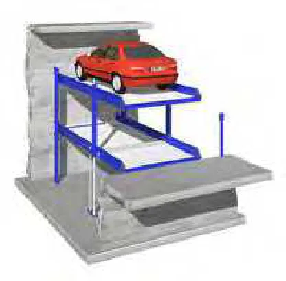
[image:17.612.224.432.114.319.2]The following Figure 1.1 shows the expected design of the project:
Figure 1.1: Expected Design
Smart Car Park System is an user friendly car parking system. This model utilizes a two-vehicle lifting system which is capable of lifting any production vehicles, for example, the luxury saloons, 4x4's and SUV's.
Under such a system, the first coming driver will park his/her car on the upper parking platform. The car will be lifted up automatically when there is another car looking for parking lot at the waiting area later, hence an extra bottom parking platform can then be provided. On the other hand, when the driver want to move his/her car out from the parking platform later on, the driver just simply operates the controller so that the platform is either lifted up or lifted down, then the driver can get into the vehicle and drives away.
3
1.2 Project Objectives
a) To design a two-level of parking platforms to increase the number of car parking lots.
b) To detect the car which park in the parking platform by using the Infrared sensor (IR sensor).
c) To lift up and lift down the parking platform by using the DC gear motor.
1.3 Problem Statement
Nowadays, the shortage of car parking lots is an unavoidable problem to the people in the town area, business district or even in the housing estate. The drivers need to spend a lot of times to find a parking lot for their vehicles. As a result, some drivers may force to park their cars far away from the destination. Sometimes, some irresponsible drivers may even park their vehicles illegally on the street and consequently cause the severe traffic problem in urban areas.
With the implementation of the Smart Car Park System, the system can increase the number of car parking lots and therefore overcome the problem of shortage of car parking lots, save the time of drivers and reduce the traffic problem in the society.
1.4 Project Scopes
4
1.5 Summarize Methodology
Firstly, literature review, especially the researches on each of the components used in this project is done.
Next, the infrared sensor circuit is designed for the detection of the car which park in upper and bottom parking platforms and the car which entering the waiting area. On the other hand, the DC gear motor circuit is also designed for lifting up and lifting down the parking platform. The hardware and the circuits of the project are designed simultaneously in order to avoid any problem dealing with the position of the circuit placed.
In addition, the programming language of the PIC microcontroller 16F877A for the project is designed according to the requirement. The programming of the PIC microcontroller is combined with the infrared sensor circuit and the DC gear motor circuit.
After completing the hardware and software of the project, the last part of final year project is the finishing. The hardware and software are combined and the outcome for project is presented.
1.6 Structure of Report
In Chapter I, the project introduction, project objectives, problem statement, project scopes, summary of methodology and the structures of report are discussed.
5
The methodology of this project is summarized in a flow chart in Chapter III. The procedure for completing the project is discussed in details in this chapter.
Result and discussion are included in Chapter IV. Basically, the simulation results for the infrared sensor circuit and DC gear motor circuit are shown in this chapter. Furthermore, some discussions regarding to the infrared sensor circuit and DC gear motor circuit are done in this chapter too.
6
CHAPTER II
LITERATURE REVIEW
The same devices of different models are compared in literature review. The device that will be compared is microcontroller PIC 16F87XA family. Then, the most suitable model for this project is chosen. Moreover, the functions and features of the infrared sensor and DC gear motor are also studied in this chapter.
2.1 Microcontroller PIC 16F87XA
A microcontroller is an integrated chip that is often part of an embedded system.
[4] The microcontroller includes a CPU, RAM, ROM, I/O ports, and timers like a
standard computer, but because they are designed to execute only a single specific task to control a single system, they are much smaller and simplified so that they can include all the functions required on a single chip. [5]
7
The great advantage of microcontrollers, as opposed to using larger microprocessors, is that the parts-count and design costs of the item being controlled can be kept to a minimum. They are typically designed using CMOS (Complementary Metal Oxide Semiconductor) technology, an efficient fabrication technique that uses less power and is more immune to power spikes than other techniques.
There are also multiple architectures used, but the predominant architecture is CISC (Complex Instruction Set Computer), which allows the microcontroller to contain multiple control instructions that can be executed with a single macro instruction. Some use a RISC (Reduced Instruction Set Computer) architecture, which implements fewer instructions, but delivers greater simplicity and lower power consumption.
Early controllers were typically built from logic components and were usually quite large. Later, microprocessors were used, and controllers were able to fit onto a circuit board. Microcontrollers now place all of the needed components onto a single chip. Since they just control a single function, some complex devices contain multiple microprocessors.
Microcontrollers have become common in many areas, and can be found in home appliances, computer equipment, and instrumentation. They are often used in automobiles, and have many industrial uses as well, and have become a central part of industrial robotics. Since they are usually used to control a single process and execute simple instructions, microcontrollers do not require significant processing power.
8
The erasing time is almost unnoticeable because once new program are loaded into the PIC microcontroller, the old program will automatically be replaced with the new program immediately. [6]
[image:23.612.123.533.318.469.2]By referring to Table 2.1, microcontroller contains the devices PIC 16F87XA family with specific information such as program memory, data SRAM, EPROM, I/O and CCP (PWM). Those devices are PIC 16F873A, PIC 16F874A, PIC 16F876A and PIC 16F877A. This information below is obtained from the data sheet Microcontroller PIC 16F877A.
Table 2.1: Microcontroller PIC 16F87XA [1]
Device
Program Memory Data
SRAM (Bytes)
EPROM
(Bytes) I/O
CCP (PWM) Bytes #Single Word
Instruction
PIC 16F873A 7.2K 4096 192 128 22 2
PIC 16F874A 7.2K 4096 192 128 33 2
PIC 16F876A 14.3K 8192 368 256 22 2
PIC 16F877A 14.3K 8192 368 256 33 2
As shown in Table 2.1, PIC16F873A and PIC16F876A devices are available only in 28-pin packages, while PIC16F874A and PIC16F877A devices are available in 40-pin and 44-pin packages. The 28-pin devices have three I/O ports, while the 40/44-pin devices have five. As a result, PIC16F874A and PIC16F877A are more suitable for final year project.
9
PIC16F876A and PIC16F877A is 8192. It is more than the single word instruction of microcontroller PIC16F873A and PIC16F874A which is 4096. For program memory, the higher of bytes and the higher of single instruction word provide advantage on choosing the PIC microcontroller for final year project.
By comparing the data Static Random Access Memory (SRAM) of microcontroller PIC 16F87XA, as shown through Table 2.1 above, microcontroller PIC16F873A and PIC16F874A have 192 bytes while the microcontroller PIC16F876A and PIC16F877A have 368 bytes of data SRAM inside it. Any of the temporary variable storage that wrote in program is stored in the RAM. With using PIC16F876A and PIC16F877A microcontrollers, any external RAM is not needed due to the original 368 bytes RAM.
In addition, by comparing Erasable Programmable Read Only Memory (EPROM) of microcontroller PIC16F87XA, microcontroller PIC16F873A and PIC16F874A have 128 bytes while microcontroller PIC16F876A and PIC16F877A have 256 bytes of EPROM. EPROM is very useful to store information such as PIN Number, Serial Number and so on. EPROM is very important because all stored data can be retained when power supply turns off. RAM does not store data permanently. Data in RAM is not retained when power supply turns off.
![Table 2.1: Microcontroller PIC 16F87XA [1]](https://thumb-ap.123doks.com/thumbv2/123dok/573838.67996/23.612.123.533.318.469/table-microcontroller-pic-f-xa.webp)
