DEPARTMENT OF ELECTRICAL AND ELECTRONIC ENGINEERING
COORDINATED CONTROL OF
A BACK-TO-BACK HVDC LINK
AUTHOR: RAMLAN BIN LATIP SUPERVISOR: DR. ALAN WATSON
DATE: SEPTEMBER 2016
i
ACKNOWLEDGEMENT
I would like to take this opportunity to express my highest gratitude to those parties who helped me on the completion of my MSc final project.
First and foremost, I would like to thank with full-hearted to my supervisor, Dr. Alan Watson who has guided me and constantly providing meaningful advice to help me implementing my project. He has been patiently giving me navigation whenever I face obstacles during carried out this project.
My heartful appreciation also goes to my family and beloved wife, Syaffiyiah Qalisyah Roslan who have been very supportive and understanding which helped me through to accomplish this project.
ii
ABSTRACT
iii
CONTENTS
CHAPTER
SUBJECT
PAGE
ACKNOWLEDGEMENT i
ABSTRACT ii
CONTENTS iii
LIST OF FIGURES vii
LIST OF TABLES x
SYMBOL AND ABBREVIATION xi
CHAPTER
1 INTRODUCTION 1
1.1 Research Background 1
1.2 Problem Statement 2
1.3 Aim 3
1.4 Research Objectives 3
1.5 Research Methodology 4
iv
CHAPTER
2 LITERATURE REVIEW 6
2.1 An Overview of HVDC System 6 2.2 Fundamental of VSC-HVDC System 8 2.3 VSC-HVDC System Configuration 9 2.4 Controller in Back to Back VSC-HVDC system 11 2.5 Phase Locked Loop (PLL) 12
CHAPTER
3 CO-ORDINATED CONTROL BACK-TO-BACK VSC
HVDC DESIGN PROCEDURE 14
v
3.7 DC Voltage Control Design 30 3.7.1 DC Voltage Control Block Diagram 30 3.7.2 DC Voltage Controller Design 31 3.8 Active Power Control Design 33 3.9 Reactive Power Control Design 34 3.10 Complete System of VSC 1 36 3.11 DC Power (DC Current) Control Design for VSC2 37 3.12 Complete System of Back-to-Back VSC HVDC System 42
CHAPTER
4 SIMULATION & ANALYSIS 44
vi
CHAPTER
5 CONCLUSION 59
5.1 Conclusion 59
5.2 Suggestion for Further Work 60
vii
LIST OF FIGURES
FIG. NO.
TITLE
PAGE
2.1 Power electronics for HVDC 7 2.2 HVDC system based on CSC technology with thyristor 8 2.3 HVDC system based on VSC technology with IGBTs 9 2.4 Basic back-to-back VSC HVDC system 10 2.5 Phase Locked Loop (PLL) 13 3.1 Overview block diagram of the VSC control system 15 3.2 ABC- conversion block diagram 17
viii
3.13 Linearized model of DC voltage control loop 32 3.14 Complete system of VSC 1 36 3.15 Power flow for VSC HVDC system 37 3.16 Equivalent circuit for the design of DC current control 38
and VSC 2 DC voltage control
3.17 Simulink block diagram for VSC 2 38 3.18 Linearized model of DC power control loop for VSC 2 40 3.19 Complete system of back-to-back VSC HVDC system 43
block diagram
4.1 Id and Iq linearized model control loop simulation result 44 4.2 PLL linearized model control loop simulation result 45 4.3 DC Voltage linearized model control loop simulation 46
result
ix
4.13 Network1 AC current output (Current source 53 1000A connected)
x
LIST OF TABLE
TABLE NO.
TITLE
PAGE
2.1 Summary of Fully Controlled High-Power Semiconductors 6
xi
SYMBOL AND ABBREVIATION
HVDC - High Voltage Direct Current UHVDC - Ultra-High Voltage Direct Current
AC - Alternating Current DC - Direct Current
IGBT - Insulated-gate Bipolar Transistor PLL - Phase Locked Loop
LCC - Line-commutated Current-source converter SCC - Self-Commutated Voltage-Source Converter PWM - Pulse Width Modulation
EMI - Electromagnetic Interference P - Active power
Pref - Active power reference value
Qref - Reactive power reference value
idref - d-axis current reference value
iqref - q-axis current reference value
- Alpha - Beta
- d-axis voltage - q-axis voltage
xii
- Three phase supply voltage - Phase a voltage
- Phase b voltage - Phase c voltage
- Three phase supply current - Rectifier terminal voltage
1 technology especially for long distance transmission and in the interconnection of the power system that has different frequency. The HVDC link is able to overcome some of the limitations of AC system such as no limit for the transmission cable length, immunity from impedance, phase angle, frequency or voltage fluctuations, lower short circuit current and improve the AC system’s controllability and stability.
2
controller to generate signal modulation also affected. A good design of controller will provide a coordinated control of HVDC link which can help to ensures positive interconnection among the controllable devices.
This project will focus on the control coordination of back-to-back HVDC link using a Matlab Simulink software. A Matlab SimPowerSystems toolbox, provided in the Matlab Simulink Software will be used to develop the power converter and control system. The simulation will show how it will respond to the modulation signal generated by the controllers. The result of the simulations will help to improve the system dynamic stability and improve the transfer capacity.
1.2Problem Statement
3
is another problem occur. The IGBT switching frequency is much faster (>1000Hz) compare to the thyristor switching frequency around 50-60Hz. This will require better power converter and control system of signal modulation generation. This project is expected to overcome the problem by developing the coordinated control of back-to-back HVDC link by using Matlab Simulink Software.
1.3Aim
• To develop a coordinated control of back-to-back HVDC link using Matlab Simulink software.
1.4Research Objectives
The scopes of this research are as follows:
1. To design VSC 1 as constant DC source.
2. To design VSC 2 as constant DC source plus an external DC cable current loop.
4
1.5Research Methodology
There are few steps of methodology that will be used in this project. The first step is to model the power system and determine the transfer function of each component of HVDC system. The model should be kept as simple as possible while still capture the important element of the system. There is two main blocks of a power converter which are VSC1 (VSC for network 1) and VSC2 (VSC for network 2).
The VSC1 design starts by developing the AC current controller. Based on the classical control system design technique, the control loop, and control parameters shall be determined. The current controller should be able to respond to an active and reactive power demand. A suitable currents value will be injected into the AC grid to get the response. The designed controller also shall be able to be used in the d-q frame.
The AC current controller is then shall be enhanced by including the Phase Locked Loop (PLL) for the purpose of grid synchronization. A d-q PLL is chosen to be used in this project design because it is the simplest choice available. Once the design completes until at this stage, the power converter should be able to control the AC grid active and reactive power at desired value.
The completed model above is then will be extended with DC voltage control. This is the end part of VSC1. The DC voltage controller shall be able to control DC voltage at a constant value even though the load resistor value is change.
5
hence control the power transmitted through back-to-back link since the current and power relation is proportional. In the DC current loop, there will be DC voltage as the inner loop. The current controller output will provide a reference voltage for the DC voltage control loop. During design this controller, the VSC1 will be considered as an ideal voltage source to the HVDC cable for design simplicity.
Once the VSC1 and VSC2 design are completed, the model of fully controlled back-to-back HVDC system will be implemented. Finally, the performance can be examined and analyze by simulation using Matlab Simulink. The simulation result will show the response of DC and AC current, voltage and power when the DC current demand is changed. The switching version of the full back-to-back HVDC system will be implemented using the same controller that have been designed.
1.6System Deliverables
This project will develop the control system model of back-to-back HVDC link. The best
control parameter shall be determined using the classical control system design techniques and
present the simulation result of the design and evaluation of the proposed controller of
6
CHAPTER 2
LITERATURE REVIEW
2.1An Overview of HVDC System
A High Voltage Direct Current (HVDC) technologies are keep developing from time to time. The HVDC technologies are started with so called HVDC “Classic” that use thyristor as its switching component. It only has turn-on capability which is one of its disadvantages. Thus, the classic HVDC is also known as Line-Commutated Current-Source Converter (LCC/ CSC) [11]. The HVDC technologies are then has been improved to HVDC “Plus” by changing the switching component from thyristor to IGBT because of the capability of IGBT that can turn-on and off. This technology is also called Self-Commutated Voltage-Source Converter (SCC/ VSC) [11].
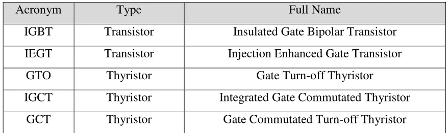
The fully controlled semiconductor devices available today for voltage high-power converters can be based on either thyristor or transistor technology (see Table 2.1) [1]:
Acronym Type Full Name
IGBT Transistor Insulated Gate Bipolar Transistor IEGT Transistor Injection Enhanced Gate Transistor
GTO Thyristor Gate Turn-off Thyristor
IGCT Thyristor Integrated Gate Commutated Thyristor GCT Thyristor Gate Commutated Turn-off Thyristor
7
Typically a VSC which is use IGBT as it switching component apply Pulse Width Modulation (PWM) operating at a higher frequency than the line frequency. Thus, will cause higher switching losses. Figure 2.1 indicates the typical losses depending on the switching frequency [11]:
Figure 2.1: Power electronics for HVDC [11]
8
Although facing many challenges, the HVDC technologies keep on growing in order to fulfill the power demand that rises every year. Rising demand will require higher power to be carried out by the transmission line. Currently, the highest rating of HVDC station is the Itaipu Power Station which is rated at 12.6GW, 600kV. The Itaipu Power Station is considered as the Ultra High Voltage Direct Current (UHVDC) because of the power rating above 10GW. In the latest technology, China is currently being investigating the possibility of using the UHVDC with voltage rating is 1,100kV for power transmissions of 10 to 13 GW per line for distances over 2,000 km [13]. New technologies will require new challenges in term of components, control, protection, cables and so forth.
2.2 Fundamental of VSC-HVDC system
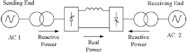
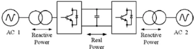
Currently, there is two technology of HVDC system. Firstly is the CSC-HVDC and the other one is VSC-HVDC. Figure 2.2 shows the basic diagram of CSC-HVDC while Figure 2.3 shows the basic diagram of VSC-HVDC [1][2]:
9
Figure 2.3: HVDC system based on VSC technology with IGBTs
The main difference of both of the technology is the switching component that is used. The thyristor is used in CSC while IGBT is used in VSC technology.
2.3 VSC-HVDC System Configuration
VSC-HVDC can be configured to several types of topology/scheme such as back-to-back HVDC system, monopolar HVDC system, bipolar HVDC system and multi-terminal HVDC system [1][2][12].
2.3.1 Back to Back VSC-HVDC system
10
Figure 2.4: Basic back-to-back VSC HVDC system
2.3.2 Monopolar VSC-HVDC system
This configuration is usually used for very long distances transmission and mostly involved very long sea cable transmission which will require submarine cable and connection. The ground electrodes are use for the return path of the currents.
2.3.3 Bipolar VSC-HVDC System
A Bipolar HVDC system is a combination of two monopolar systems. It is usually used if the power or transmission capacity exceeds the single pole capacity. The total power capacity will be split into two poles with each pole cover 50% of the total capacity. The advantage of this configuration, it is still able to provide 50% of power transmission during the maintenance of one of the pole.
11
2.3.4 Multi-terminal VSC-HVDC System
This configuration is the combination of more than two sets of the bipolar system. This configuration is applied in a large grid which can offer more economical of DC transmission line and provide better flexibility in power dispatch and stabilization of the AC system [7].
2.4 Controller in Back to Back VSC-HVDC system
The controller of the VSC-HVDC system for converter 1 (rectifier) and converter 2 (inverter) controller design are identical but both converter controllers have no communication between them and operate independently. There is four mains controller:
a. Current controller (inner loop)
The current controller is the inner loop of the active and reactive power controller. The inner loop response shall be faster than the outer loop. It tracks d-q current component to control AC current in case of the changes of load current that may cause the load changes or fault. The d-q components is a first order plant and both are independently related [3].
b. Active power controller (outer loop)
The active power controller is used to keep the power transmitted to the DC link at the reference value, Pref. In order to control the active power flow or DC
voltage level, the active current, id shall be used in the inner current loop control
![Figure 2.1: Power electronics for HVDC [11]](https://thumb-ap.123doks.com/thumbv2/123dok/471963.51616/20.612.154.543.206.405/figure-power-electronics-for-hvdc.webp)
![Figure 2.4: Basic back-to-back VSC HVDC system [3]](https://thumb-ap.123doks.com/thumbv2/123dok/471963.51616/23.612.105.542.76.236/figure-basic-back-to-back-vsc-hvdc-system.webp)
