i
UNIVERSITI TEKNIKAL MALAYSIA MELAKA
FACULTY OF ENGINEERING TECHNOLOGY
CAR SEAT SECURITY SYSTEM FOR UNATTENDED
CHILD USING GSM MODULE
This report submitted in accordance with requirement of the Universiti Teknikal Malaysia
Melaka (UTeM) for the Bachelor Degree Project in Electrical Engineering Technology
(Industrial Power)
Submitted by
Muhammad Hafiszan Bin Mohd Akhir B071210306
ii
APPROVAL
This report is submitted to the Faculty of Engineering Technology of UTeM as a partial fulfilment of the requirements for the degree of Bachelor of Electrical Engineering Technology (Industrial Power) with Honours. The member of the supervisory committee is as follow:
………
(Principal Supervisor)
...
iii
DECLARATION
“I, hereby declare that this thesis entitled, CAR SEAT SECURITY SYSTEM FOR UNATTENDED CHILD USING GSM MODULE is a result of my own research
idea concept for works that have been cited clearly in the references.”
Signature : ………
Author’s Name : MUHAMMAD HAFISZAN BIN MOHD AKHIR
v
ABSTRAK
vi
ABSTRACT
vii
DEDICATION
viii knowledge throughout the development of this project.
Furthermore, special thanks also I dedicate to University Technical Malaysia Melaka for supporting and providing information sources that assisted my studies. My sincere appreciation to the staffs at the Department of Electrical Engineering Technology (Industrial Power) specifically, who had put efforts on the lectures and always nurtured and guided me with precious advices. Thank you for willing to share those experiences that really helped me.
ix
LIST OF SYMBOLS AND ABBREVIATIONS xvi
CHAPTER 1 1
INTRODUCTION 1
1.0 Introduction 1
1.0.1 Explanation of Simplified Block Diagram 1
1.1 Background 2
x
2.1.2 Vehicle’s Interior Movement Detection and Notification System by Fairuz R. M. Rashidi and Ikhwan H. Muhamad 9
2.1.3 Wireless System to Detect Presence of Child in a Baby Car Seat
by Joseph Kinman Lee and Darren Paul 10
2.1.4 System and Method for a Child Safety Seat Having Sensing and
Notification Abilities by Owen Chelsea 12
2.2 Microcontroller 14
2.2.1 Pin Configuration 14
2.2.2 PIC Architecture 16
2.3 GSM Module 17
2.3.1 Introduction of GSM module 17
2.3.2 GSM Technology 18
2.3.3 GSM Architecture 19
2.3.4 Mobile Switching Centre (MSC) 19
2.4 Proteus 8.0 Professional 20
2.5 AT command 20
2.5.1 Basic Command and Extended Command 21
2.5.2 General Syntax of Extended AT Command 21
2.6 Voltage regulator 22
2.7 Force Sensing Resistor 23
2.8 LM35 Temperature Sensor 25
2.9 Level Converter – MAX232 Driver/Receiver 26
2.10 Mobile Phone 27
xi
3.5 Construction of Hardware 34
3.5.1 GSM SIM900A 34
3.5.2 The Microcontroller (SK40C) 34
3.5.3 LM35 35
3.5.4 The IR Obstacle Sensor 36
3.5.5 LCD 37
3.5.6 Hardware Prototype 38
3.6 System overview diagram 38
CHAPTER 4 41
4.4.1 Results for IR obstacle sensor 44
4.4.2 Results for LM35 45
4.5 Overall Project Analysis and Discussion 46
xii
CHAPTER 5 48
CONCLUSION AND RECOMMENDATION 48
5.0 Conclusion 48
5.1 Future Work 49
APPENDIX 50
Coding 50
Gantt Chart 54
xiii
LIST OF FIGURES
Figure 1.1: Block Diagram for process that uses GSM 2
Figure 1.2: The Temperature inside and Outside the Car That Kill
Children 3
Figure 1.3: Graph about Causes of Heatstroke Death by Jan Null (2011) 4 Figure 2.1: Flow Chart of Alarm System of the Project of Baby Seat Belt
Alarm System 8
Figure 2.2: Block Diagram of Illustrating a Control Unit 9
Figure 2.3: Flow Chart of the System for Vehicle’s Interior Movement
Detection and Notification System 10
Figure 2.4: An Illustration of the Invention of Wireless System to Detect
Presence of a Child in a Baby Car Seat 11
Figure 2.5: The Process of the System for Wireless System to Detect
Presence of a Child in a Baby Car Seat 12
Figure 2.6: Design of Safety Seat for System and Method for a Child
Safety Seat Having Sensing and Notification 13
Figure 2.7: PIC16F877A Characteristic 16
Figure 2.8: Architecture of a GSM Network 19
Figure 2.9: Voltage Regulator Circuit 23
Figure 2.10: Resistance is Inversely Proportional to Force 23
Figure 2.11: FSR Schematic Circuit 24
Figure 2.12: LM35 25
Figure 2.13: USART to the PC 26
Figure 2.14: PC to USART 26
Figure 3.1: Flow Chart of the Project 30
Figure 3.2: Block Diagram of the Project 32
Figure 3.3: Flow Chart of the Software Development 32
Figure 3.4: Flow Chart of GSM 33
xiv
Figure 3.6: SK40C PIC Kit 35
Figure 3.7: LM35 Temperature Sensor 36
Figure 3.8: IR Obstacle Sensor 37
Figure 3.9: LCD Display 37
Figure 3.10: Proteus 8 Professional 38
Figure 3.11: Illustration of the System 40
Figure 4.1: Overall Project 42
Figure 4.2: Simulation Circuit 43
Figure 4.3: Hardware Circuit 44
Figure 4.4: Show that the LCD display when the IR sensor trigger and the
SMS that will received by a user via GSM. 45
Figure 4.5: Show that the LCD display when the LM35 trigger the high
temperature and the SMS that will received by a user via GSM. 46
xv
LIST OF TABLE
Table 2.1: Microcontroller PIN 14
Table 2.2: Determination in the GSM System 18
Table 2.3: Analogue Voltage Value Error! Bookmark not defined.
Table 4.1: Data Obtained for IR sensor 45
Table 4.2:Data Obtained for LM35 Sensor 46
xvi
LIST OF SYMBOLS AND ABBREVIATIONS
BBS = Bulletin board services
CMOS = Complementary metal–oxide semiconductor
GSM = Global System communication for mobile phone
EDGE = Enhanced Data Rates for GSM Evolution
EEPROM = Electrically erasable programmable read-only memory
EECON1 = Contains control bits
EECON2 = Register does not exist physically and serves to protect EEPROM from accidental writing.
EEDATA = Holds read data or that to be written
EEADR = Contains an address of EEPROM location being accessed.
GPRS = General Packet Radio Service
PIC = Programmable Interface Controller
PDU = Protocol description unit
PCB = Printed circuit board
xvii RAM = Random Access Memory
ROM = Read-only memory
SMS = Short Messaging Service
SFR = Special Function Register
SPDT = Single pole, double throw
SSR = Solid State Relays
TTL = Transistor–transistor logic
RF = Radio Frequency
1
CHAPTER 1
INTRODUCTION
1.0 Introduction
One of the most recently used in communication system in the present universe of innovation is Global System for Mobile Communication (GSM). It has turn out to be extremely prominent and one of the wireless communication system that is dependable to use. Moreover, it is also accessible to be used by individual and very user friendly. One of the factors that makes this system dependable to use is because of the cost. The cost is exceptionally effective and affordable to own for individual who use this system. The network system is extended as the demand is growing. In the Car Set Security System for Unattended Child, there is one of the examples of the system that uses GSM.
1.0.1 Explanation of Simplified Block Diagram
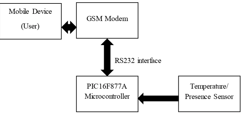
This is the explanation of each block diagram for the Figure 1.0 below.
Mobile Device: A cellular phone that contain a SIM card. This device communicates through the GSM modem and mobile user will received an SMS using GSM technology.
2 PIC Microcontroller: Contains the software components that can execute a certain command that have been coded.
RS-232 interface for PIC microcontroller to GSM modem: For basic serial communication between a PIC microcontroller and GSM modem. Generally only needed to connect the Ground, Transmitter and Receiver lines.
RS232 interface
Figure 1.1: Block Diagram for process that uses GSM
1.1 Background
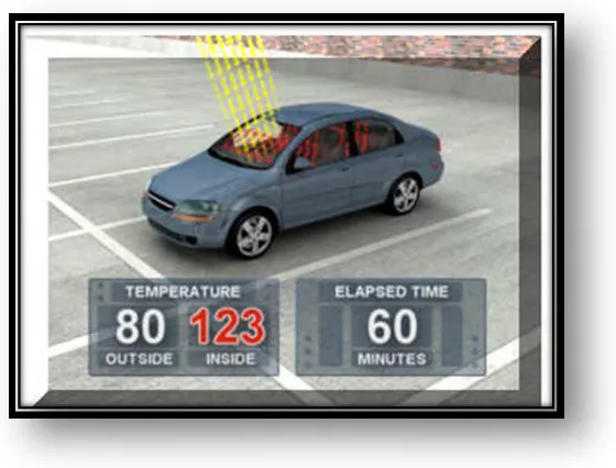
According to Ferrara, et al Pietro (2013) there are a lot number of cases that related to the death of child where the child had been left in a car by their parents due to the heat stroke and hyperthermia. When the body absorbs too much heat, this will cause a hyperthermia (Luethi M, Meier B, Sandi C, 2008). Children are easily to develop hyperthermia that adults when inside a closed and hot vehicle. There are two factors that make children to be more prone to hyperthermia than adults: children have a greater surface area body mass ratio compared to adults and a children thermoregulation is less efficient than adults.
3 car will die because of the hot temperature from the outside and it will affect the child inside the car. Studies have proven that children heat rate is three to five times faster than adults.
Figure 1.2: The Temperature inside and Outside the Car That Kill Children
Some might say that leaving the vehicle’s with window slightly open can reduce the warming rate inside the car. This does not basically can reduce the warming rate inside the car because children’s bodies warm at a faster rate than adults.
However, caution must be practised to prevent the unwanted incident to be occurred. Therefore, to prevent from this kind of bad situation happens; the vehicle that are used must be equipped with a device or some system that can be used to warn parents if they were negligent when leaving the vehicle. As a driver, they are usually left their car in a far place from their destination such as open air parking lot. So, there is no other way to communicate with them except through mobile phones connectivity. Hence, the notification system needs to have access to a wide-range phone communication such as Global System for Mobile Communication (GSM).
4 secondary alert to detect the body temperature of child that has been left in the car for more than half an hour and then send another SMS text message to parents alerting temperature body of the child rises. So by this project, it will make parents more alert if they were leaving their child alone in the car and can avoid from bad incidents to occur.
1.2 Problem Statement
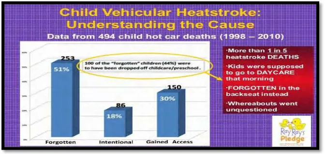
In this era, people’s daily life is more to choose to follow their fixed schedule and live in rushing and under pressure every day. And when there is a changes of routine, this may cause a distraction and become the main reason why they can forgot their own child in the car. There have been some cases about the tragic death of children that have been mistakenly left in the vehicles because the parents had forget to bring them together when they have reached the destination. Example case that happened in Malaysia is a father left his child for almost five hours in a car. This accident happened due to parents having busy schedule. To prevent this kind of incident from occurring, one system to overcome this case need to be created immediately after stopping the engine and locking the car. This system will alert the parents before they walk away from the car and leave the child inside.
The Figure 1.3 below shows the causes of children who died in a vehicles because of the heatstroke.
5 1.3 Objectives
The objective of this project are:
a) To design the circuit system as to detect the existing human body in a car.
b) To propose a notification system that is intently to be a low-cost system so that it can be easily implemented and installed in any types of vehicles.
1.4 Scope of Project
This project has two types of sensor which is IR obstacle sensor and the LM35 sensor. The IR obstacle sensor will sense a presence of a baby on a car seat and for the LM35, this sensor will sense a surrounding temperature inside a car. Then the PIC will send a signal to GSM to send a SMS to a user. This system comes will a small part of circuit and can be implemented in any kind of vehicles.
1.5 Thesis Outlines
This Child in Car Alarm System is consists of five chapters as are outlined as follows.
Chapter I: Describes about the overview of the project including the background, objectives, problem statement and scope of the project.
Chapter II: Explains about the reviews on previous researches that are related to this project. Before starting the project, the background and literature review about development of the components that are using to build this system need to study and doing research well.
6
Chapter IV: Presents the result of project. This project has two parts of result. The first part is result at the simulation and the other part is result from real prototypes. It also consist the analysis and discussion of the results.
7
CHAPTER 2
LITERATURE REVIEW
2.0 Introduction
In this chapter will study more about the previous journals and discuss on the previous project. This chapter also consists of the theoretical concepts and some useful ideas to implement in this project. Various types of references were consulted and reviewed to ensure effectiveness to implement this project.
2.1 Related Works
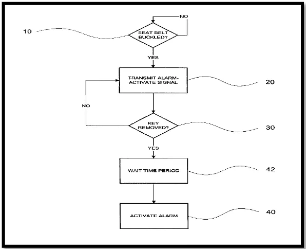
2.1.1 Baby Seat Belt Alarm System by Fred Mesina (2005).
8 The alarm system will function when there is a child been buckled on a car seat and the car key is removed from ignition at the same time. The controller may be including belt buckled sensor, a key removed sensor, a transmitter and additional devices such as horn, air conditioning and some other devices.
Based on Figure 2.1 below shows the flow chart of the steps on how to activate an alarm when there is an abandon child in the car.
10- To detect either the seat belt is buckled or not.
20- If the seat belt is already buckled, transmitter will send a signal to a key module.
30- To detect whether the key I already removed from a keyhole or not.
42- Timer, or waiting period for delaying the activation of the alarm.
40- The key module will activates the alarm to alert the driver.