MUHAMMAD NIZAM KAMARUDIN
MUHAMMAD NIZAM KAMARUDIN
A thesis submitted in fulfilment of the requirements for the award of the degree of Doctor of Philosophy (Electrical Engineering)
Faculty of Electrical Engineering Universiti Teknologi Malaysia
For my wife Sahazati..
iv
ACKNOWLEDGEMENT
I am grateful to ALLAH, our Lord and Cherisher, for guiding me to develop and complete this thesis. Verily, there is neither might nor any power except from Allah. Salutation to our beloved prophet MUHAMMAD(Sallallahu a’alaihi wassalam) and to his companion.
My sincere appreciation goes to my supervisor PROF. MADYA DR. ABDUL RASHID HUSAIN, whose guidance, advice, assistance and constructive comments was valuable. I am also deeply indebted to my co-supervisors PROF. MADYA DR. MOHAMAD NOH AHMAD and PROF. MADYA DR. ZAHARUDDIN MOHAMED for their invaluable advice.
I would like to thank my wife DR. SAHAZATI MD. ROZALI for being patient and supportive during all these years. To my daughter HUWAIDA and my son MUHAMMAD HADIF, your constant love and laughing has putting me in momentum to complete this thesis. To my parents PN. ZAINON HASSIM and EN. KAMARUDIN ABDUL RAZAK for their encouragements. To my research colleague and friends for kindness and willingness to help. I would also like to thank the developers of the utm thesis LATEX project for preparing this thesis template.
I am eternally indebted to the MINISTER OFEDUCATIONMALAYSIAand the UNIVERSITITEKNIKALMALAYSIAMELAKA(UTeM) for providing me funding and opportunity for this PhD study. Special appreciation to the member of BAHAGIAN CUTI BELAJAR UTeM for their constant support, especially to former assistant registrar PN. SITI SALWAH AHMAD. To EN. MOHD NAZRUL MOHD SHAFRI and ERDALIA ERNADAUD, may Allah give you all the best in return.
ABSTRACT
vi
ABSTRAK
TABLE OF CONTENTS
CHAPTER TITLE PAGE
DECLARATION ii
DEDICATION iii
ACKNOWLEDGEMENT iv
ABSTRACT v
ABSTRAK vi
TABLE OF CONTENTS vii
LIST OF TABLES x
LIST OF FIGURES xi
LIST OF ABBREVIATIONS xiv
LIST OF SYMBOLS xv
LIST OF APPENDICES xvii
1 INTRODUCTION 1
1.1 Introduction 1
1.2 Problem Statement 2
1.3 Research Objectives 4
1.4 Scopes of Thesis 5
1.4.1 Purely numerical system 6
1.4.2 Numerical representation of a dynamical
system 6
1.5 Contributions of the Research Works 7
1.6 Thesis Organization 8
2 LITERATURE REVIEW 10
2.1 Introduction 10
2.2 Uncertainties and Disturbances 10
2.3 Nonlinear Systems with Multifarious Control
viii
2.4 The Existing Control Strategies for Bounded
Control Problems 15
2.5 Summary 20
3 METHODOLOGY FOR BOUNDED BACK-STEPPING
CONTROLLER DESIGN 23
3.1 Introduction 23
3.2 Preliminary Study: Stabilization by using Direct
Lyapunov Method 24
3.3 Development of Bounded Control Law 25
3.3.1 Bounded Control Algorithm Based on
Sontag 26
3.3.2 Realization of Proposition 3.1 28 3.3.3 Effectiveness of Bounded Control
Algo-rithm: A preliminary view 29
3.4 Mixed Back-stepping and Lyapunov Redesign
Control Technique 30
3.4.1 Back-stepping control strategies 31 3.4.2 Back-stepping with Lyapunov Redesign 33 3.4.3 Designing a Final Control Law 36 3.5 Numerical Case: Robust Bounded Control for
Nonlinear System with Exogenous Disturbances 39 3.5.1 Conventional Back-stepping and
Lya-punov Redesign 40
3.5.2 Bounded Back-stepping and Lyapunov
Redesign 44
3.6 Summary 48
4 SIMULATION RESULTS AND DISCUSSION 49
4.1 Introduction 49
4.2 Results 49
4.2.1 Regulation 50
4.2.2 Control Signal Energy and Power 51 4.3 Analysis of Invariance Set of Solutions: A
Comparison Between Bounded Back-stepping and
Conventional Back-stepping Controller 53 4.4 Significance of Control Parameters for Asymptotic
5 APPLICATION OF BOUNDED BACK-STEPPING
CONTROLLER TO A VARIABLE SPEED WIND
TURBINE SYSTEM 67
5.1 Introduction 67
5.2 Design Assumption and Scope 70
5.3 Two-mass Wind Turbine System 70
5.3.1 Rotor Model 71
5.3.2 Aero-turbine Model 71
5.4 Variable Speed Control Design 74
5.4.1 Variable Speed Control using
Conven-tional Back-stepping 74
5.4.2 Variable Speed Control using Bounded
Back-stepping 76
5.5 Results 79
5.5.1 Testing Condition 79
5.5.2 Free Running 82
5.6 Summary 85
6 CONCLUSION AND SUGGESTIONS 86
6.1 Conclusion 86
6.2 Suggestions and Recommendations of Future
Works 87
REFERENCES 90
x
LIST OF TABLES
TABLE NO. TITLE PAGE
2.1 Summary on selected literature 21
4.1 Initial control parameters 50
4.2 Sum of squared error and steady state error 50
4.3 Power and energy produced by all control laws 52 4.4 Results for various C1 when C2 = 10 (10,000 seconds
simulation time) 58
4.5 Results for various C2 when C1 = 30 (10,000 seconds
simulation time) 60
4.6 Effect of varyingd0towards SSE and control signal power 64 5.1 Nomenclature for two-mass wind turbine system 70 5.2 SSRSE for rotor speed in 100 seconds run time 81
5.3 Betz limit 84
C.1 Fuzzy rules for tuningC1 andC2 113
LIST OF FIGURES
FIGURE NO. TITLE PAGE
1.1 Regulatedx1 3
1.2 Control signal,u 3
1.3 Summarized problem of back-stepping technique 3
1.4 Set of solutions 4
1.5 Conceptual block diagram for system introduced by Choi in
[22] 6
1.6 Two-mass wind turbine structure 7
1.7 Typical power coefficient characteristic for fixed pitch angle 7 2.1 Summary on control techniques for uncertain systems 12 2.2 Fuzzy adaptive control systems having input saturation
anti-windup scheme (courtesy from [134]) 16
2.3 The LQR Design Method (courtesy from [134]) 17
3.1 Stabilizedxwhen perturbed by initial conditionx(0) = 20 29 3.2 Control signal for trajectory starting fromx(0) = 20 29 3.3 History ofD0(t) =d0 +|G|+|G|e−α0t whend0 = 1 30 3.4 Conceptual block diagram for system in equation
(3.21)-(3.22) 31
3.5 Conceptual block diagram for a manipulated system in
equation (3.24) 33
3.6 Conceptual block diagram for back-stepped system in
equation (3.27)-(3.28) 33
3.7 Conceptual block diagram for bounded back-stepped system in equation (3.27)-(3.28) with Proposition 3.1 - A nominal
system 33
3.8 Conceptual block diagram for system in equations
(3.54)-(3.55) 40
4.1 History of the stabilizedx1 51
4.2 Phase portrait (trajectory) for initial conditionX = [1−1]T 51 4.3 Control signals produced by a variable structure control in
xii
4.4 Control signals produced a normal back-stepping control law
in equation (3.73) 51
4.5 Control signals produced a bounded back-stepping control
law in equations (3.90), (3.91), (3.92) 52
4.6 Magnification of control signals - A comparison between normal back-stepping and bounded back-stepping control
laws 52
4.7 Surface of Lyapunov function and its derivative 54 4.8 Compact set / asymptotic stability region created by the
largest initial condition in equation (4.1) 54 4.9 Phase portrait of system (3.54)-(3.55) using normal
back-stepping 54
4.10 Phase portrait of system (3.54)-(3.55) using bounded
back-stepping 55
4.11 Relationship between SSE andC1, whenC2 = 10 58 4.12 Relationship between control signal power and C1, when
C2 = 10 58
4.13 Regulatedx1 for variousC1, whenC2 = 10 59
4.14 Relationship between SSE andC2, whenC1 = 30 61 4.15 Relationship between control signal power and C2, when
C1 = 30 61
4.16 Regulatedx1 for variousC2, whenC1 = 30 62
4.17 Magnification of Figure 4.16(f) 62
4.18 Systematic heuristic tuning approach forC1 andC2 63 4.19 Relationship between control signal power and bounded
parameterd0 65
4.20 Relationship between SSE and bounded parameterd0 65
4.21 Regulatedx1 for variousd0 65
4.22 Control signal for variousd0 65
4.23 The effect of functionD0(t) =d0+|G|+|G|e−α0t (for variousd0)
towards the regulatedx1 and the overall control signal 65 4.24 How function D0(t) =d0+ |G|+|G|e−α0t decays with respect to
variousd0 65
5.1 Main research area in wind energy conversion system 68 5.2 Summary of control strategies for wind turbine system 68 5.3 The control strategy proposed by Inthamoussou [131]. Tg is
the control signal (generator torque), andΩis the rotor speed 69 5.4 The control strategy proposed by Beltran et al. [179]. Tg is
5.7 Demanded rotor speedωr as in equation (5.64) 80
5.8 Actual rotor speedωr 80
5.9 Rotor speed error - using normal back-stepping control law 80 5.10 Rotor speed error - using bounded back-stepping control law 80 5.11 Trajectory,y1versusy2 - Using normal back-stepping 80 5.12 Trajectory,y1versusy2 - Using bounded back-stepping 80 5.13 Control signal for normal back-stepping controller 81 5.14 Control signal for bounded back-stepping controller 81
5.15 Wind speed profile 83
5.16 Demanded rotor speedωr∗ = λopt
R υ 83
5.17 ωr versusω∗r - Using bounded back-stepping control law 83
5.18 ωr versusω∗r - Using normal back-stepping control law 83
5.19 Tip-speed-ratio,λ- Using bounded back-stepping control law 83 5.20 Tip-speed-ratio,λ- Using normal back-stepping control law 83 5.21 Power coefficient,Cp - Using bounded back-stepping control
law 83
5.22 Power coefficient, Cp - Using normal back-stepping control
law 83
5.23 Initial control signal - Bounded back-stepping control law 83 5.24 Initial control signal - Conventional back-stepping control
law 83
5.25 Power distribution 84
5.26 Power flow diagram 85
B.1 Nonlinear system and linearized system trajectory 111 C.1 (a) - Membership functions for z and dzdt, (b) - Membership
functions for C1 andC2 (c) - Surface of C1, (d) - Surface of
C2 114
C.2 Regulatedx1 by bounded back-stepping control law 114
C.3 History ofC1andC2 during regulation 114
D.1 Eulers approximation 115
xiv
LIST OF ABBREVIATIONS
ANN - Artificial Neural Network
ASR - Asymptotic Stability Region
FL - Fuzzy Logic
GA - Genetic Algorithm
GSA - Gravitational Search Algorithm
LMI - Linear Matrix Inequality
LQR - Linear Quadratic Regulator
LQG - Linear Quadratic Gaussian
LUT - Look-up-table
MPC - Model Predictive Control
MRAC - Model Reference Adaptive Control
NMRAC - Nonlinear Model Reference Adaptive Control N-PID - Nonlinear Proportional-Integral-Derivative
PD - Proportional-Derivative
PI - Proportional-Integral
PID - Proportional-Integral-Derivative
PSO - Particle Swarm Optimization
QFT - Quantitative Feedback Theory
SMC - Sliding Mode Control
SSE - Sum of Squared Error
SSRSE - Sum of Squared Rotor Speed Error
LIST OF SYMBOLS
R - Rotor blade radius
υ - Wind speed
ρ - Air density
Cp(λ, β) - Power coefficient
λ - Tip speed ratio
β - Pitch angle
γ - Gearing ratio
ωr - Rotor speed
ωg - Generator speed
Jr - Rotor inertia
Jg - Generator inertia
Kr - Rotor external damping
Kg - Generator external damping
Br - Rotor stiffness
Bg - Generator stiffness
Tm - Aerodynamic torque
Tg - Generator torque / Electromagnetic torque
Ths - High-speed shaft torque
Tls - Low-speed shaft torque
θg - Generator-side angular deviation
θr - Rotor-side angular deviation
Pcapt - Captured power
Tcapt - Captured torque
ℜn - Real number vector withn-size
C1, C2 - Control parameters for back-stepping controller
C1upper, C2upper - Maximum control parameter for back-stepping controller
C1lower, C2lower - Minimum control parameter for back-stepping controller
xvi
ε - Parameter for pseudo function
A - Antecedent linguistic term for fuzzy logic controller B - Consequent linguistic term for fuzzy logic controller P - Dimension of the input space for fuzzy logic controller Ni - The number of linguistic terms of the ith antecedent
LIST OF APPENDICES
APPENDIX TITLE PAGE
A List of Publications 107
B Linearization Technique for Nonlinear System 109
C On-line Tuning forC1 andC2 112
D Euler’s Approximation 115
E Sum of Squared Error 117
CHAPTER 1
INTRODUCTION
1.1 Introduction
The field of control engineering is greatly advanced in order to fulfils great industrial demand. Industrial sectors such as manufacturing, aerospace [7, 8], robotics [9], transportation [10, 11, 12], traffic flow [13], maritime [14], wind turbine system [15], flight control design [16, 17] and many more are expanding rapidly. Most of the systems are nonlinear and to gain the asymptotic stability and robustness of these systems requires advanced control techniques. Nonlinear systems do not fulfil superposition principle as linear systems do. Nonlinear systems absorb nonlinear phenomena such as chaos, saturation, limit cycle, finite escape time, having multiple isolated equilibrium points, and unpredictable. Thus, solving nonlinear systems requires advance control techniques. The presence of uncertainties and exogenous disturbances in the nonlinear systems dynamic is sometimes inevitable, and give catastrophic effect to the stability and robustness of closed loop systems. As such, developing a robust control for nonlinear systems with uncertainties and exogenous disturbances offer challenge to control research community.
highly on system parameters and dynamics. For that reason, back-stepping controller normally produces high magnitude control signal with large power depending on the system order and the location of the perturbed initial state.
1.2 Problem Statement
In this thesis, two main problem statements are outlined. These statements explain the shortcomings of the ideal back-stepping controller in term of the control signal magnitudes, control signal energy and the asymptotic stability condition based on ideal Lyapunov function.
Statement 1
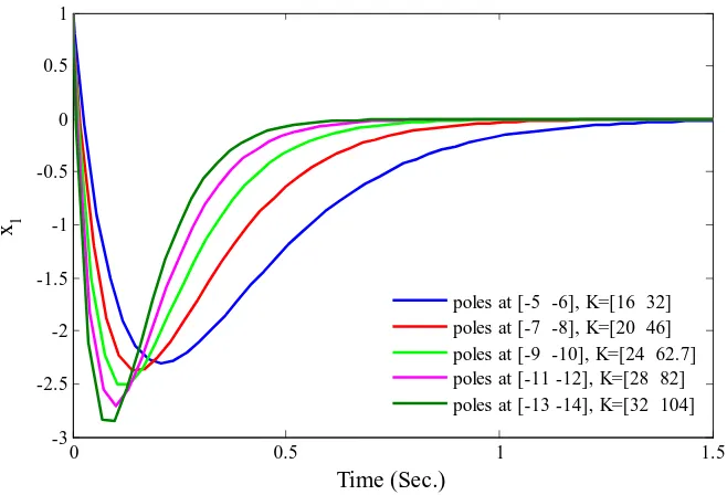
Quite often, control law primarily aims at the asymptotic stability and asymptotic disturbance rejection of the closed loop system. However, very little research focuses on the control signal magnitude and the power produced by the controller while achieving the asymptotic stability and the asymptotic disturbance rejection [21, 22]. Hence, bounded control problem has become an incessant research in control engineering field. For illustration, it is easy to stabilize unstable system by forcing their poles to the left-hand-side of the S-plane so that the closed-loop system stable. Theoretically, placing the closed-loop poles near to −∞ may result in fast regulation rate but require high energy as a trade-off. For example, consider a linear system
˙
x=Ax+Bu (1.1)
where the statex∈ ℜn, system matrixA∈ ℜn×n, input matrixB ∈ ℜn×mand control
inputu ∈ ℜm. By pole placement approach, states xcan be regulated to equilibrium
3
consider numerical values for system (1.1) as
A=
"
1 2 3 4
#
andB =
"
1 0
#
(1.2)
Then, placing the closed loop poles at−5and−6yieldsK = [16 32]T. Figure 1.1 and Figure 1.2 depict the regulatedx1 and the control signal respectively. Placing closed
0 0.5 1 1.5
-3 -2.5 -2 -1.5 -1 -0.5 0 0.5 1 Time (Sec.) x 1
[image:24.595.155.484.218.442.2]poles at [-5 -6], K=[16 32] poles at [-7 -8], K=[20 46] poles at [-9 -10], K=[24 62.7] poles at [-11 -12], K=[28 82] poles at [-13 -14], K=[32 104]
Figure 1.1: Regulatedx1
loop poles more toward−∞will result in faster regulation rate (Figure 1.1), but will increase the feedback gain K and hence, increase the magnitude of the initial control signal (Figure 1.2). This observation shows that avoiding excessive control signal is crucial in the control design yet really important in practice.