i
AN ANALYSIS OF SIGLE-LAYER DIFFERENTIAL CPW-FED NOTCHED-BAND TAPERED-SLOT UWB ANTENNA
MUHAMMAD FATHI BIN AZHAR
This Report Is Submitted In Partial Fulfillment of Requirement for the Bachelor Degree of Electronic Engineering (Telecommunication Electronics)
Faculty of Electronic and Computer Engineering Universiti Teknikal Malaysia Melaka
ii
UNIVERSTI TEKNIKAL MALAYSIA MELAKA
FAKULTI KEJURUTERAAN ELEKTRONIK DAN KEJURUTERAAN KOMPUTER
BORANG PENGESAHAN STATUS LAPORAN
PROJEK SARJANA MUDA II
Tajuk Projek : An Analysis of Singe-Layer Differential CPW-Fed Notched-Band Tapered-Slot UWB Antenna Sesi
Pengajian : 1 1 / 1 5
Saya MUHAMMAD FATHI BIN AZHAR
mengaku membenarkan Laporan Projek Sarjana Muda ini disimpan di Perpustakaan dengan syarat-syarat kegunaan seperti berikut:
1. Laporan adalah hakmilik Universiti Teknikal Malaysia Melaka.
2. Perpustakaan dibenarkan membuat salinan untuk tujuan pengajian sahaja.
3. Perpustakaan dibenarkan membuat salinan laporan ini sebagai bahan pertukaran antara institusi pengajian tinggi.
4. Sila tandakan ( √ ) :
SULIT* *(Mengandungi maklumat yang berdarjah keselamatan atau kepentingan Malaysia seperti yang termaktub di dalam AKTA RAHSIA RASMI 1972)
TERHAD** **(Mengandungi maklumat terhad yang telah ditentukan oleh organisasi/badan di mana penyelidikan dijalankan)
TIDAK TERHAD
Disahkan oleh:
__________________________ ___________________________________
(TANDATANGAN PENULIS) (COP DAN TANDATANGAN PENYELIA)
iii
DECLARATION
“I declare that this report “An Analysis of Single-Layer Differential CPW-Fed Notched-Band Tapered-Slot UWB Antenna” is the result of my own research except as cited in
the references”.
Signature : ……….
iv
“I hereby declare that I have read this report, entitled “An Analysis of Single-Layer Differential CPW-Fed Notched-Band Tapered-Slot UWB Antenna” and it fulfills the
requirements of the scope and quality for the Bachelor of Electronic Engineering (Telecommunication Electronics).”
Signature : ………...
Supervisor’s Name : DR. MOHD AZLISHAH BIN OTHMAN
v
Special dedication:
vi
ACKNOWLEDGEMENT
First of all, I would like to express my deepest appreciation to my supervisor, Dr Azlishah bin Othman who had giving me guidance in completing this final year project. Besides that, I would like to thank other lectures and post graduate students of Faculty of Electronic and Computer Engineering for their cooperation, valuable information, suggestion and guidance in helping me to complete this final year project.
vii
ABSTRACT
viii
ABSTRAK
ix
TABLE OF CONTENTS
CHAPTER TITLE PAGE
PROJECT TITLE i
DECLARATION iii
DEDICATION iv
ACKNOWLEDGEMENT vi
ABSTRACT vii
ABSTRAK viii
TABLE OF CONTENTS ix
LIST OF TABLES xi
LIST OF FIGURES xii
LIST OF ABBREVIATION xiv
I INTRODUCTION 1.1 PROJECT SUMMARY 1
1.2 PROJECT INTRODUCTION 1
1.3 PROBLEM STATEMENT 10
1.4 OBJECTIVES OF PROJECT 11
1.5 SCOPE OF PROJECT 11
x
2.2 CPW-FED OCTAGON SHAPE SLOT ANTENNA
FOR UWB APPLICATIONANTENNA 13
2.3 UWB MICROSTRIP ANTENNA BASED ON CIRCULAR PATCH TOPOLOGY WITH STEPPED FEEDLINE AND PARTIAL GROUND PLANE 15
2.4 A NOVEL UWB ANTENNA WITH DUAL NOTCHED BANDS FOR WIMAX AND WLAN APPLICATIONS 19
III METHODOLOGY 3.1 INTRODUCTION 25
3.2 ANTENNA SPECIFICATION 26
3.3 ANTENNA STRUCTURE 27
3.4 PRELIMINARY RESULT 32
3.5 ANTENNA SIMULATION 33
IV RESULT AND DISCUSSION 4.1 INTRODUCTION 36
4.2 SIMULATION RESULT 36
4.2.1 Study of Notch-Band Characteristic 44
4.3 MEASUREMENT RESULT 53
V CONCLUSION 55
xi
LIST OF TABLES
No Title Page
2.1 Parameters Value of Designed Antenna 14
2.2 Antenna Parameters 21
3.1 Antenna Specification 27
3.2 Design Parameters of Antenna A 28
3.3 Design Parameters of Antenna B 30
4.1 Simulated Gain at All Frequencies for Antenna A 42 4.2 Simulated Gain with ROGERS RT 5880(lossy) as
substrate 43
4.3 Simulated Gain at All Frequencies for Antenna B 50
xii
LIST OF FIGURES
NO TITLE PAGE
1.1 Types of Antenna 3
1.2 Example of Microstrip Antenna 4
1.3 Example of the Gain in Radiation Pattern 5 1.4 UWB versus other radio communication systems 6 1.5 Basic Design Concept for Band-Notched UWB Antenna 9 2.1 Geometry of the Proposed CPW Fed Antenna 13 2.2 Simulated Return Loss for Different Slot Width 15 2.3 Circular Monopole Patch Antenna with Two-Block Fed
by Stepped Microstrip Line 16
2.4 Diameter Versus Return Loss 17
2.5 Ground Length Versus Return Loss 18
2.6 Step Width Versus Return Loss 19
2.7 Configuration and Parameters for UWB Antenna 20
2.8 Configuration with Dual Notch Band 22
2.9 Simulated Band Rejection of Proposed Antenna 23
3.1 Flow Chart of the Project 26
3.2 Antenna A Structure 27
3.3 Layout of Antenna A 28
3.4 Antenna B Structure 29
3.5 Layout of Antenna B 30
3.6 Value for S11 for Antenna A 32
xiii
3.8 A Screenshot of CST Microvave Studio 34
4.1 Antenna A Structure 37
4.2 Simulated Return Loss for Antenna A 37
4.3 Return Loss for Antenna A with Different Values for h0 38 4.4 Return Loss for Antenna A with Different Values for Ra 38
4.5 Gain at 3.1 GHz 39
4.6 Gain at 4 GHz 39
4.7 Gain at 5 GHz 40
4.8 Gain at 6 GHz 40
4.9 Gain at 7 GHz 40
4.10 Gain at 8 GHz 41
4.11 Gain at 9 GHz 41
4.12 Gain at 10 GHz 41
4.13 Gain at 10.6 GHz 42
4.14 Antenna B Structure 44
4.15 Simulated Return Loss for Antenna B 45
4.16 Return Loss for Varying Length of Stub 46
4.17 Gain at 3.1 GHz 47
4.18 Gain at 4 GHz 47
4.19 Gain at 5 GHz 47
4.20 Gain at 5.5 GHz 48
4.21 Gain at 6 GHz 48
4.22 Gain at 7 GHz 48
4.23 Gain at 8 GHz 49
4.24 Gain at 9GHz 49
4.25 Gain at 10 GHz 49
4.26 Simulated Radiation Pattern for Antenna B 52 4.27 Measured Return Loss for Fabricated Antenna B 53
xiv
LIST OF ABBREVIATION
UWB - ULTRAWIDE BAND
CPW - COPLANAR WAVEGUIDE
FCC - FEDERAL COMMUNICATION COMMISSIONS
VSWR - VOLTAGE STANDING WAVE RATIO
1
CHAPTER I
INTRODUCTION
1.1Project Summary
This project is started by designing two CPW antennas that operate in the ultra-wideband range of frequencies from 3.1 GHz to 10.6 GHz. The designed antennas then will be simulated. The design and simulation processes are done by using CST (Computer Simulation Technology) software. These 2 antennas then will be compared from one to another in term of the antennas performance before one antenna is proposed and fabricated. The comparison of these antennas is made by analyzing the value of the s-parameters and the antennas’ gain.
1.2Project Introduction
2
In a transmission process, a radio transmitter supplies an electric current oscillating at radio frequency to the antenna's terminals before the antenna radiates the energy from the current as electromagnetic waves. In reception, an antenna intercepts some of the power of an electromagnetic wave to produce a tiny voltage at its terminals before the voltage is applied to a receiver for the amplification process. The antennas are widely used for most systems and components that are connected wirelessly such as cell phones, walkie-talkie, and satellite communication systems.
Antennas consist of metallic conductors that are connected to the receiver electrically through the transmission line. The transmitter forces an oscillating current of electrons through the antenna thus creating an oscillating magnetic field around the antenna elements. This process encourages the charge of the electrons to create an oscillating electric field along the elements.
3
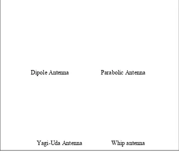
Dipole Antenna Parabolic Antenna
[image:17.612.147.507.54.362.2]Yagi-Uda Antenna Whip antenna
Figure 1.1: Types of Antenna
Nowadays, basic antennas such as dipole and vertical design are rarely used as the technology grows rapidly. Moreover, there are many types of antenna that has been developed to improve the performance in term of the directivity and the gain of the antenna.
Microstrip antenna is an antenna that is developed to overcome problems facing by antennas that had been developed before. Microstrip is light in term of weight, can produce high gain, and simpler to design and construct. These advantages make
4
[image:18.612.128.513.248.401.2]matching techniques for antennas. The performance of a microstrip antenna is depending on the antenna’s parameters such as dielectric parameters, height, length, thickness, and frequency. These parameters can be optimized to improve the performance of the particular antenna. Microstrip patch array antennas consist of a very thin metallic strip that is patched on ground plane according to particular designs. The performance of a microstrip antenna can be obtained by analysing the dimension of frequency, directivity, r efficiency, return loss, and the standing wave ratio.
Figure 1.2: Example of Microstrip Antennas
Resonant frequency is the tendency of a system to oscillate with greater amplitude at some frequencies. At these frequencies, small periodic forces can produce large
amplitude oscillations since this system has stored energy. This phenomenon may occur at all types of waves and can have some small amount loss called damping.
The gain of an antenna is the main criteria used to determine the antenna’s
5
technique is very useful for the optimization process to improve the antenna performance.
[image:19.612.111.538.116.296.2]
Figure 1.3: Example of the Gain in Radiation Pattern of a Microstrip Patch Antenna
Bandwidth is another fundamental parameter for an antenna. Bandwidth describes the range of frequencies over which an antenna can properly radiate or receive wave energy. The desired bandwidth is one of the parameter that is needed to be decided before an antenna is designed. IEEE defines bandwidth as “The range of frequencies within which the performance of the antenna, with respect to some characteristic,
conforms to a specified standard.” However, in practise, bandwidth is normally
determined by measuring characteristics such as SWR and S-parameters over certain range of interested frequencies.
Return loss is the loss of signal power resulting from the reflection caused by a discontinuity in a transmission line or optical fiber. This discontinuity can be a mismatch with the terminating load or with a device inserted in the line. The return loss is usually expressed as a ratio in decibels (dB).
(1.1)
6
measure of how well devices or lines are matched. A match is good if the return loss is high. A high return loss is desirable and results in lower insertion loss. Return loss is used in modern practise in preference to SWR because it has better resolution for small values of reflected wave.
Ultra-wideband is a radio technology which may be used at a very low energy level for short-range, high-bandwidth communications using a large portion of the radio spectrum. Similar to spread spectrum, UWB communications transmit in a manner which does not interfere with conventional narrowband and carrier wave used in the same frequency band. Ultra-wideband is a technology for transmitting information spread over a large bandwidth (>500 MHz); this should, in theory and under the right circumstances, be able to share spectrum with other users. Regulatory settings by the Federal Communications Commission (FCC) in the United States intend to provide an efficient use of radio bandwidth while enabling high-data-rate personal area
network (PAN) wireless connectivity; longer-range, low-data-rate applications; and radar and imaging systems. Ultra-wideband (UWB) signals operate from 3.1GHz to 10.6GHz as been released by the Federal Communications Commission (FCC).
7
Plenty types of antennas have been designed for single-ended signal operation in recent years. However, differential signal operation has been widely used in the radio frequency systems. When single-ended antennas are integrated with differential circuits, baluns are needed to transform differential signals into single-ended signal, which cause energy loss and decreases the efficiency of the system. Thus, differential antennas are more suitable for differential signal operation due to the direct integration with differential circuits. An antenna is said to be single layer when the patches and the feeding network are placed on the same layer.
Coplanar waveguide is a type of electrical transmission line which can be fabricated using printed circuit board technology, and is used to convey microwave-frequency signals. On a smaller scale, coplanar waveguide transmission lines are also built into monolithic microwave integrated circuits. Conventional coplanar waveguide (CPW) consists of a single conducting track printed onto a dielectric substrate, together with a pair of return conductors, one to either side of the track. All three conductors are on the same side of the substrate, and hence are coplanar. The return conductors are separated from the central track by a small gap, which has an unvarying width along the length of the line. Away from the central conductor, the return conductors usually extend to an indefinite but large distance, so that each is notionally a semi-infinite plane.
8
A feedline is used to feed the radio waves to the rest of the antenna structure, or in receiving antennas collect the incoming radio waves, convert them to electric currents and transmit them to the receiver. There are many different methods of feeding and four most popular methods are microstrip line feed, coaxial probe, aperture coupling and proximity coupling. Microstrip line feed is one of the easier methods to fabricate as it is a just conducting strip connecting to the patch and therefore can be considered as extension of patch. It is simple to model and easy to match by controlling the inset position. However the disadvantage of this method is that as substrate thickness
increases, surface wave and spurious feed radiation increases which limit the bandwidth.
Coaxial feeding is feeding method in which that the inner conductor of the coaxial is attached to the radiation patch of the antenna while the outer conductor is connected to the ground plane. Aperture coupling consist of two different substrate separated by a ground plane. On the bottom side of lower substrate there is a microstrip feed line whose energy is coupled to the patch through a slot on the ground plane
separating two substrates. This arrangement allows independent optimization of the feed mechanism and the radiating element. Normally top substrate uses a thick low dielectric constant substrate while for the bottom substrate; it is the high dielectric substrate. The ground plane, which is in the middle, isolates the feed from radiation element and minimizes interference of spurious radiation for pattern formation and polarization purity. Proximity coupling has the largest bandwidth, has low spurious radiation. However fabrication is difficult. Length of feeding stub and width-to-length ratio of patch is used to control the match.
9
and WLAN to overlap, producing signals interference at the frequencies. Therefore, antennas that can be operated from 3.1GHz to 10.6GHz and have sharp and controllable notch from 5.15GHz to 5.825 GHz characteristic are needed for the UWB
communication system. The notch function characteristic can be developed for an antenna by undergoing several techniques. For example, addition of a pair of stubs and slits can be added to the patch of an antenna to develop a controllable notch
characteristic. This notch characteristic operates similarly to the band stop filter that passes most frequencies unaltered, but attenuates those in a specific range to very low levels.
Figure 1.5: Basic design concept for band-notched UWB antenna
10
Besides that, due to small separation between the radiating patch and its ground plane, microstrip antennas can only handle low radio frequency power.
The antennas can be used successfully if the frequencies are in range of electromagnetic spectrum. Electromagnetic spectrum covers from the lowest to the higher frequencies. The lower frequencies are normally used in radio communication while the higher frequencies are used in short wavelength communication.
Electromagnetic spectrum consists of radio wave, microwave, infrared, visible light, ultraviolet, X-ray, and gamma ray.
1.3Problem Statement
Ultrawide Band (UWB) signals operate from 3.1GHz to 10.6GHz as been released by the Federal Communications Comission (FCC). However, there are some existing wireless communication system partially overlap with UWB system. The
communication system, WLAN operates at 5.15GHz – 5.825 GHz thus allowing UWB and WLAN to overlap, causing signals interference at the frequencies. Therefore, an antenna that can be operated from 3.1GHz to 10.6GHz and have sharp and controllable notch from 5.15GHz to 5.825 GHz characteristic is needed.
1.4Objectives