‘I/We* admit that I/we* have read this dissertation and in my/our* opinion this dissertation is satisfactory in the aspect of scope and quality for the best bestowal of
Bachelor of Mechanical Engineering (Automotive)
Signature : ... Supervisor Name (I) : Mr Ahmad Bin Rivai
Date : ...
Signature : ... Supervisor Name (II) : Prof. Dr. Mohd Radzai Bin Said
VALIDATION OF BAR VIBRATION BY USING FEA
AZFAR NAZMI BIN NIKMATLAH
This report was submitted in accordance with the partial requirements for the honor of Bachelor of Mechanical Engineering (Automotive)
Faculty of Mechanical Engineering Universiti Teknikal Malaysia Melaka
ii
“I verify that this report is my own except summary and extract that every one of it I have clarify the resource”
iii
Dedicated
To my beloved Mum and Dad,
To my respectful Supervisor,
To my honorable Lecturers,
&
iv
ACKNOWLEDGEMENT
The author would like to say thanks to writer’s PSM supervisor, Mr. Ahmad Rivai for his advices, help, and guidance throughout the progression in completing my PSM report.
The cooperation given by the laboratory management especially the technician of UTeM’s Instrumentation Lab that has been helping in completion of the project is appreciated.
v
ABSTRAK
vi
ABSTRACT
vii
TABLE OF CONTENT
CHAPTER TITLE PAGE
CONFESSION ii
DEDICATION iii
ACKNOWLEDGEMENT iv
ABSTRAK v
ABSTRACT vi
TABLE OF CONTENT vii
LIST OF TABLES x
LIST OF FIGURES xi
LIST OF SYMBOLS xv
LIST OF APPENDIX xvi
1 INTRODUCTION 1
1.1 Objective 2
1.2 Scopes 2
1.3 Problem Statement 3
2 LITERATURE REVIEW 4
2.1 Background 4
2.3 Theories of Vibration 5
2.4 Types of Vibration 6
2.4.1 Free Vibration 6
viii
2.5 Modal Analysis 14
2.5.1 Frequency Response Measurement 15
2.6 Natural Frequency 16
2.7 Mode Shape 19
2.8 Finite Element Method 21
2.8.1 FEA Simulation 22
3 METHODOLOGY 24
3.1 Background 24
3.2 Project Workflow 25
3.3 Bar Information 26
3.4 Calculation 27
3.5 Experimental Modal Testing 29
3.5.1 Apparatus 29
3.5.2 Procedures 29
3.6 FEA Simulation (ABAQUS/CAE) 32
4 RESULT & DISCUSSION 34
4.1 Background 34
4.2 Calculation Result 35
4.3 Experimental Result 36
4.3.1 Experimental Possible Error 41
4.4 FEA Result 42
4.5 Result Comparison 47
4.5.1 Natural Frequencies Comparison 47
4.5.2 Percentage of Error 49
4.5.3 Mode Shapes Comparison 51
5 CONCLUSION & RESULT 52
5.1 Background 52
5.2 Conclusion 53
ix
REFERENCES 55
x
LIST OF TABLES
NO. TITLE PAGE
2.6 Natural frequency formula for fixed-free cantilever bar 17 (Source: UTeM (2007))
3.3 Bar Parameter 27
4.2 First five natural frequency results obtained from calculation 35
4.3 Natural Frequencies obtained from experiment 41
4.4 Natural Frequencies obtained from FEA (ABAQUS/CAE) 47
xi
LIST OF FIGURES
NO. TITLE PAGE
2.3 Representation of the measured vibration exposure 5 (Source:www.ccohs.ca/oshanswers/phys
_agents/vibration/vibration_intro.html)
2.4.1.1 Mass-spring-system of free undamped vibration 7 (Source: http://en.wikipedia.org/wiki/Vibration)
2.4.1.2.1 Mass-spring-damper system of free damped vibration 9 (Source: http://en.wikipedia.org/wiki/Vibration)
2.4.1.2.2 Effect of damping ratios 11
(Source: en.wikipedia.org/wiki/File:Damped_Free_ Vibration.png)
2.4.2 Effect of damper 13
xii
2.5.1 Process to determined modal parameters 15 (Source: http:ww.agilent.com)
2.5.2 FRF theory 16
(Source: http:ww.agilent.com)
2.6.1 Russel D.A. Experimental Setup 18
(Source: http://paws.kettering.edu/drussell/bats- new/modal.html)
2.6.2 Comparison of FRF results for three impact locations 18 (Source: http://paws.kettering.edu/drussell/bats-
new/modal.html)
2.7.1 First three mode shapes of fixed-free cantilever beam 20 (Source: UTeM (2007))
2.7.2 First two mode shapes obtained from Russell D.A. 20 modal testing
(Source: http://paws.kettering.edu/drussell/bats- new/modal.html)
2.8 Meshed Bar 21
(Source: http://www.tfhrc.gov/safety/pubs/05063/ Chapt5.htm)
2.8.1 FEA Simulation result using MSC Patran 23 (Source: http://www.mscsoftware.com/modal
analysis using MSC Patran)
3.3 (a) Mild steel bar 26
xiii
3.5.2.1(a) Experimental setup 29
3.5.2.1(b) Schematic diagram of experimental setup 30
3.5.2.2 Impact location 30
3.5.2.3 DAQ board 30
3.5.2.4 Accelerometer position 31
3.5.2.5 DeweFRF channel setup 31
3.6.1 Parameter used in ABAQUS 32
3.6.2 BCs created in ABAQUS/CAE 33
4.3(a) Graph of Magnitude against Frequency for Point 1 36
4.3(b) Graph of Magnitude against Frequency for Point 2 37
4.3(c) Graph of Magnitude against Frequency for Point 3 38
4.3(d) Graph of Magnitude against Frequency for Point 4 39
4.3(e) Graph of Magnitude against Frequency for Point 5 40
4.4(a) First mode of vibration 42
4.4(b) Second mode of vibration 43
4.4(c) Third mode of vibration 44
xiv
4.4(e) Fifth mode of vibration 46
4.5.1 Graph natural frequencies against corresponding 48 mode number
4.5.3(a) Mode shapes of fixed free cantilever beam from past 51 Study
(Source: Whitney S. (1999))
xv
LIST OF SYMBOLS
A = cross section area, m2 a = acceleration, ms-2
B = width, m
c = damping constant E = Young’s Modulus, GPa
F = force, Nm
Fd = damping force
Fs = spring force, Nm
fd = damped natural frequency, rad/s
fn = natural frequency, Hz
h = thickness, m
I = 2D moment of beam, m4
K = spring constant, Nm
L = length, m
r = ratio of harmonic force frequency over undamped natural frequency v = velocity, ms-1
X = amplitude of vibration π = pie, 3.142
ζ = damping ratio ρ = density, kg/cm3
λn = coefficient of vibration
xvi
LIST OF APPENDIX
NO. TITLE PAGE
A Working Plan for PSM 1 58
B Working Plan for PSM 2 59
C Mode Shapes view from z-axis 60
D Experiment Apparatus 61
E Measured Impulse Response in DeweFRF software 62
1
CHAPTER I
INTRODUCTION
2
using computer software (FEA). Experiments have been conducted by many past researchers which have helped us enhance our understanding in this field. FEA is a numerical technique that can be used to approximate the structural dynamic characteristics of vibrating mechanical systems. The Finite Element technique can be used for structural dynamic studies of existing equipment or to evaluate the dynamic characteristics of machines and structures prior to fabrication.
1.1 Objective
The objective of this project is to validate by using Finite Element Analysis (FEA) the testing of bar vibration.
1.2 Scopes
These project scopes consist of the following: 1. Literature research on vibration
2. Determination of the natural frequencies and mode shapes by testing 3. Finite Element Analysis (FEA) simulation
3
1.3 Problem Statement
4
CHAPTER II
LITERATURE REVIEW
2.1 Background
In order to measure and validate bar vibration, it is essential to understand theories of vibration. Hence, information and data gathered from previous study was studied deeply. In addition, collected information from internet, books and other sources were used as guidance and reference.
5
2.3 Theories of Vibration
The study of vibration has started long times ago by many investigators. Pythagoras, who was born in 582 B.C, studied the music produced by the vibration of strings. Galileo, who was born in A.D 1564, also investigated stringed musical instruments as well as pendulum oscillations. According to Palm III (2007), electrical circuits can have oscillatory voltages or currents, but these are not called vibratory system, and their study is not called vibration. Air pressure oscillation is called sound, but the study of sound is called acoustics, not vibration.
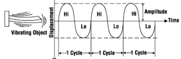
The term vibration is usually used to describe the motion of mechanical objects that oscillate or have the potential to oscillate. Figure 2.3 shows vibration data from a vibrating object. Oscillation or vibration of a mechanical object is caused by a force or moment that tries to return the object to an equilibrium or rest position. Vibration is commonly expressed in terms of frequency such as cycles per second (cps), Hertz (Hz), cycles per minute (cpm) or (rpm) and strokes per minute (spm). The vibration of a system involves the transfer of its potential energy to kinetic energy and kinetic energy to potential energy, alternately.
[image:22.595.170.469.587.686.2]The most important element in vibration is elasticity and mass. In order to vibrate, the system must have both. This means that all solids are capable of vibrating under the right condition because solids possessed both elasticity and mass.
Figure 2.3: Representation of the measured vibration exposure (Source:
6
2.4 Types of Vibration
Vibration can be divided into 2 main groups either free vibration or forced vibration.
2.4.1 Free Vibration
7
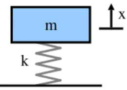
[image:24.595.259.389.159.251.2]2.4.1.1 Free Undamped vibration
Figure 2.4.1.1: Mass-spring-system of free undamped vibration (Source: http://en.wikipedia.org/wiki/Vibration)
Assume the damping is negligible and that there is no external force applied to the mass. The force applied to the mass by the spring is proportional to the amount the spring is stretched "x" (assume the spring is already compressed due to the weight of the mass). The proportionality constant, k, is the stiffness of the spring and has units of force/distance.
The force generated by the mass is proportional to the acceleration of the mass as given by Newton’s second law of motion.
The sum of the forces on the mass then generates this ordinary differential equation: