APPROVAL
I admit that had read this dissertation and in my opinion this dissertation is satisfactory in the aspect of scope and quality for the bestowal of Bachelor of
Mechanical Engineering (Design and Innovation)
Signature : ………
Name of 1st Supervisor : Mr. Nor Azmmi Bin Masripan
DESIGN AND ANALYSIS OF SAFETY MOBILE PLATFORM
MOHD AMRI BIN MOHAMED KHAIRI
This report is proposed to fulfilled some of the requirements to be honor with Bachelor of Mechanical Engineering (Design and Innovation)
Faculty of Mechanical Engineering Universiti Teknikal Malaysia Melaka
i
DECLARATION
“I verify that this report is my own work except for the citation and quotation that the source has been clarify for each one of them”
Signature :………..
ii
DEDICATION
iii
ACKNOWLEDGEMENT
First and foremost, I would like to convey my sincere thank you to my
supervisor En. Nor Azmmi Bin Masripan, who is willing to offer his support throughout
my final year project; He has graciously contributed his time, patience, and guidance in
helping me completing my project. His experience in this related topic has also given
me a boost of confidence in conducting my experimental work. Not to forget, I
would also like to thank him for re-checking my report writing thoroughly and
frequently. Without him, I would never achieve what I have meant to complete. He has
never given up on me when I doubt myself in completing this project. His constant
encouragement and guidance had brought me to the final stage of my project.
As for En Ahmad Rivai and to all my lecturers for supervising me throughout
the first stage of my final year project, I would like to give thousand thanks and
regards. They had taught me various ways to approach a study and research. They were
also a good listener and an excellent advisor. Their patience in conducting long hour
discussion had allowed me to explore new ideas for my project.
Finally, I would like to thanks to my future wife Nurhidayah and to all my
friends to help and guide me and also discussed about my project. Without their moral
support, I can’t finish this project. Hopefully, this report will be used as guidance to
iv
ABSTRAK
Dewasa ini, kerja-kerja yang dilakukan ditempat yang tinggi memerlukan tahap
dan ciri-ciri keselamatan yang tinggi untuk mencegah dan mengelak sebarang kejadian
dan kecelakaan yang tidak diingini berlaku seperti terjatuh, tergelincir dan sebagainya.
Kejadian seperti ini akan memburukan imej dan juga kredibiliti sesebuah syarikat atau
organisasi. Platfom keselamatan bergerak digunakan secara meluas di sektor-sektor
industri perkilangan antaranya ialah seperti industri berasaskan minyak dan gas,
industri simen dan batu kapur, industri pembinaan dan juga industi penjagaan dan
baikpulih banggunan dan sebagainya. Penggunaan platfom keselamatan bergerak ini
membantu meningkatkan tahap keselamatan kepada pengguna dan perkerja yang
berkerja ditempat yang tinggi disamping memudahkan ianya mudah dikendalikan dan
mudah dibawa ke mana saja untuk membuat kerja-kerja yang berkaitan. Platfom
keselamatan bergerak ini juga hendaklah mematuhi standad yang ditetapkan oleh
sesebuah syarikat mengikut faktor saiz ketinggian pekerja. Faktor keselamatan dan
kemudahan yang terdapat pada platform keselamatan bergerak ini membuatkan
kebanyakan industri memilih untuk menggunakannya disamping menjimatkan kos
kerana ianya boleh bergerak dan tidak perlu untuk membina banyak platfom untuk
satu-satu kerja yang memerlukannya pada satu-satu-satu-satu masa. Pada data yang didapati selepas
v
ABSTRACT
Latterly, works which does place high need a high level and high safety features
to prevent and avoid any accident and disaster that are not needed to happen such as
falls, slips and others. This incident would turn a bad image and perception and also the
credibility of the company or organization. Mobile safety platform widely used in many
sectors of manufacturing industry and also industry based on oil and gas, cement
industry and aerospace, construction industry and many more. The use of safety mobile
platform helps to increase the level of safety to the consumer and workers working at
height beside facilitate it maneuverable and easy to bring to wherever to make works
those related. The safety mobile platform also must abide standard that prescribed by
one company following the height of the employees. The safety, security and facility
factor that there were to mobile platform make it the most choose by industrial to
deploy it beside save cost because it can move and do not need to construct many
platform for each work that need it in a singles time. In the analysis, the structure of the
vi
TABLE OF CONTENT
CHAPTER TOPIC PAGE
DECLARATION ii
DEDICATION iii
ACKOWLEDGEMENT iv
ABSTRAK v
ABSTRACT vi
TABLE OF CONTENT vii
LIST OF FIGURES xi
LIST OF TABLE xiii
LIST OF SYMBOLS xiv
I INTRODUCTION 1
1.1 Objective 2
vii
CHAPTER TOPIC PAGE
1.3 Project Background 2
1.4 Problem Statement 6
1.5 Current Product 9
II LITERATURE REVIEW 10
2.0 Introduction 10
2.1 Safety Mobile Platform 11
2.1.1 Others type of mobile platform 13
2.2 Pipe 16
2.3 Uses of Pipe 17
2.4 Manufacturing of Pipe 17
2.5 Pipe joining 18
2.6 Mild Steel 19
2.7 Pure Bending 20
2.8 Stress and Strain 22
2.9 Torsion 24
2.10 Finite Element Analysis and Method 25
2.10.1 History 26
2.10.2 Application 27
2.10.3 Element types 28
viii
CHAPTER TOPIC PAGE
III METHODOLOGY 31
3.0 Introduction 31
3.1 The Load and Constrain of the Platform 32 3.2 The Features of Safety Mobile Platform 33 3.3 Detail design of the Safety Mobile Platform 37 3.4 Case Analysis of the Safety Mobile Platform 39 3.4.1 Assumption for these three case analyses 40 3.5 Case 4 and 5, staircase step analysis 41 3.5.1 The assumption for the case 4 and 5 42
IV RESULT AND DISCUSSION 43
4.0 Introduction 43
4.1 The Analysis for Case 1, 2 and 3 44
4.1.2 Result of Case 1, 2 and 3 45
4.2 Analysis of Staircase Steps for case 4 and 5 52 4.2.1 Result of Staircase Steps Analysis 53
V CONCLUSION 58
RECOMMENDATION 59
REFERENCES 60
ix
LIST OF FIGURES
NO. TITLE PAGE
Figure 1.0 Existing Safety Mobile Platform 5
Figure 1.2 Vibrating I-Beam 6
Figure 1.3 Mobile Platform ThyssenKrupp 7
Figure 1.4 Mobile Platform ThyssenKrupp 7
Figure 1.5 Several features 8
Figure 2.0 Safety Mobile Platform 12
Figure 2.1 Body harness and clamping system 12
Figure 2.2 MMP-Kit Basic Shown 13
Figure 2.3 MMP-K2 kits Mobile Platform 14
Figure 2.4 Platforms for Aircraft Maintenance 15 Figure 2.5 The platform is portable and easy to store 15
Figure 2.6 Metal pipe uses for structure 16
Figure 2.7 Pure Bending 20
Figure 2.8 Stress and Strain Curve for Structural Steel 23
Figure 2.9 a) 24
x
LIST OF FIGURES
NO. TITLE PAGE
Figure 3.0 Methodology Chart 31
Figure 3.1 Safety mobile platform 33
Figure 3.3 Safety Mobile Platform Detail Drawing 1 (Original) 37 Figure 3.4 Safety Mobile Platform Detail Drawing 2 with
new design staircase 38
Figure 3.5 Case 1, 2 and 3 analysis 39
Figure 3.6 Case 4 and 5 original and improvement design 41 Figure 4.1 Analysis result of case 1, 2 and 3 44 Figure 4.2 The comparison graph of maximum stress between
these two materials 47
Figure 4.3 Case 1 displacement analysis 48
xi
Figure 4.9 Graph comparison of maximum stress original
and improvement design. 55
Figure 4.10 Comparison of displacement between original
and improvement design 56
xii
LIST OF TABLE
NO. TITLE PAGE
Table 3.1.1 Material properties for ASTM and Mild Steel 32
Table 3.2.2 Parts of Safety Mobile Platform 34
Table 4.0 Result of case 1, 2, and 3 for ASTM-A-36 Steel
(Yield strength = 250 MPa). 45
Table 4.1 Result of case 1, 2, and 3 for Mild Steel
(Yield strength = 220 MPa). 45
Table 4.2 Result of original design analysis 53
xiii
LIST OF SYMBOLS
Mpa = Mega Pascal, Nm-2
N = Newton, kgms-2
= Stress
kg = Kilogram
1
CHAPTER I
INTRODUCTION
Safety mobile platform help and increase the safety support for the works at
height. As usual the height is above two meter. The structure of the platform shall have
safety characteristics like handrail, staircase, handle and many more. It’s also shall have
a point to worker hook their safety harness. Workers’ who working at height should
wear safety harness in order to prevent from falling. This mobile platform also used to
lift the light equipment such as tools, tool box, maintenance tool and many more. Only
the light equipment can be lift up. It is because the platform can’t be use for platform to
place heavy machine because of its stability, toughness, and many more. It’s only for
human as platform to do such certain work.
The structure of this safety mobile platform is drawn with use Solidworks
software. This software is good and specializes in structure design and also it is very
easy to use and learned. The analysis for this platform is used Cosmos software which is
compatible in Solidworks software. Cosmos software is very suitable in order to
analysis such a simple structure and easy to study and learned. The material and beam
structure to construct this product such as I-Beam, Channel beam, mild steel plate, steel
hollow rod and many more. As usual, the steel rod is used because of its toughness and
2
1.1 Objective.
The objective for this project is as below:
1. Make a research and study the previous products and its structure and safety
for the mobile safety platform.
2. Make the drawing and design with use Solidworks software and analysis
with Cosmos software.
3. Redesign the product and optimize alongside with analysis.
.
1.2 Scope:
1 Search all of the information regarding project. Include journals, materials,
structures, related to drawing, and many more.
2 Identify all of the parameters and problem of the product. Create a drawing for
previous product and select the material based on research and findings using
Solidworks 2007 sofware.
3 Analyze the current product using Cosmos software.
4 Identify the problem of the current product.
5 Redesign the product and make some improvement.
3
1.3 Project Background
A mobile platform and suspension system shall be certified by a licensed
professional engineer competent in structural design as being in conformity with this
project. A mobile platform used for lifting site personnel or jumpers shall be designed
to meet the following criteria and specifications:
a) The suspension system shall be designed to minimize tipping of the
platform due to movement of the individuals occupying the platform.
b) The mobile platform shall be capable of supporting, without failure, its
own weight and at least five times its maximum intended load.
c) The mobile platform shall be equipped with a guardrail system and shall
be enclosed from the toe board to mid-rail.
d) A grab rail shall be installed inside the entire perimeter of the mobile
platform.
e) The mobile platform shall have anchor points for safety harnesses or
safety belts for all persons carried on the platform. The anchor points
shall be designed and placed to best suit the movements of anyone on the
platform.
f) The mobile platform shall be free of rough or exposed edges.
g) The mobile platform shall have a slip resistant floor surface.
h) Welding of the mobile platform and its components shall be performed
by a qualified welder familiar with the weld grades, types and materials
specified in the platform design.
i) The mobile platform shall be conspicuously posted with a plate or other
permanent marking which indicates the weight of the platform and its
4
The persons on the mobile platform shall wear a safety harness or safety belt. The
mobile platform shall be limited to a capacity of four persons. Individuals shall keep all
parts of their bodies inside the mobile platform during raising and lowering to avoid
pinch points. Individuals may not stand on the top rail, midrail or toe board of the
mobile platform. A mobile platform may not be used in winds in excess of 25 miles per
hour, electric storms or other adverse weather conditions which could affect the safety
of individuals.
1.4 Problems statement.
1.4.1 Safety issue (Injuries News from www.bnet.com)
Worker falls off platform: Failure to provide fall protection: Spinal injury:
Quadriplegia: Verdict
Law Reporter, Nov 1998
Worker falls off platform: Failure to provide fall protection: Spinal injury:
Quadriplegia: Verdict.
Woodbury, 24, was working for an excavation subcontractor on a construction
project. As he was disassembling a work platform, he fell 11 feet to an underground
walkway. He suffered a fracture at C6, rendering him a quadriplegic. He requires
24-hour attendant care and has incurred medical expenses totaling about $350,000. A
recent college graduate and temporary field technician earning about $14,500 annually,
he is currently taking vocational classes. Woodbury sued the general contractor,
alleging failure to provide fall protection. Plaintiff claimed defendant had agreed to
provide overall supervision and coordination of job-site safety, yet its employees had
little knowledge of the state fall protection safety rules applicable to construction
projects. The jury awarded $11.5 million. Plaintiff's experts were Sally Niles,
5
Wilhette Gibbons, occupational safety, Salem, Or.; John Dahlberg, life care planning,
Denver, Colo.; and Lowell Bassett, economics, Seattle, Wash. Defendant's experts were
Bruce Poinsette, occupational safety, Wilsonville, Or.; Hank Lageman, vocations,
Beaverton, Or.; and John Goveia, economics, Portland, Or.
Plaintiff's Counsel: Ray Thomas, Doug Swanson, and Jim Coon, all of Portland,
Or. [Documents in this case are available through the Court Documents section at p.
356, courtesy of Mr. Thomas.] Copyright Association of Trial Lawyers of America
Nov.
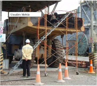
Figure 1.0: Existing Safety Mobile Platform
6
Following (E. Russell Johnston,Jr. et al. 2004) the main problem for the
structure is the material and beam use. Usually, I-beam is used as main structure and
foundation for the platform. The sizes of the structure or material if define by the
calculation. I-beams (also known as W-beams or double-T esp. in Polish and German)
are beams with an I- or H-shaped cross-section ("W" stands for wide flange). The
horizontal elements are flanges, while the vertical element is the web. The
Euler-Bernoulli beam equation shows that this is a very efficient form for carrying both
bending and shear in the plane of the web. The cross-section has a reduced capacity in
the transverse direction, and is also inefficient in carrying torsion, for which hollow
structural sections are often preferred.
Figure 1.2: Vibrating I-Beam
(Source: http://en.wikipedia.org/wiki/I_beam)
The other problem of the current mobile platform is some of the design is not
friendly user. These are only mobile but not have others characteristic like very
functional, light weight, ecstatic and many more. When design, we should determine the
7
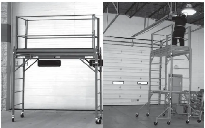
1.4 Current Product
The current product like figure below show a safety mobile platform produced
by ThyssenKrupp Services Company.
Figure 1.3 and 1.4 Mobile Platform ThyssenKrupp
(Source: www.thyssenkrupp.com)
The ThyssenKrupp Safway’s mobile work platform are one of the safest option for
painters, plasterers, maintenance workers and various other trades that require a firm
working platform. The secure features for this product are:
1. A swing-in gate on each side of the platform offers safe access, and guardrail
panel always provide the correct guardrail location, regardless of the platform
level.
2. Two guardrail panels (complete with toe boards) connect to provide proper
guardrail protection on all four sides.
3. There are no loose nuts and bolts and no special tools are required for
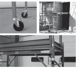
8
Figure 1.4: several features
(Source: www.thyssenkrupp.com)
This company history in scaffold design and services is based on product strength
and durability, a standard evident in the construction of mobile work platforms.
Durability features and benefits include:
1. Rigid square steel construction
2. Special side brace configuration that protects the plywood deck
3. Platform side braces that attach to frames with heavy duty, spring-loaded lock
pins that are secured when rotated
9
This safety mobile platform are available in three height (2m, 3m, and 4m), and
their ease of use is boasted through the product’s name. The mobility and accessibility
of the platform is clear through and abundance of features and benefit:
1. Easily set up by one person
2. Glides through 75cm wide doorways
3. Independent adjustment of each ladder frame permits use on stairways
4. Platform adjust up or down 10cm increment
5. Side braces allow movement over lower obstacles and eliminates the need for
lower cross braces
6. Workers can climb ladder frame at either end for easy access