Simple Dynamic Overmodulation Strategy for Fast
Torque Control in DTC of Induction Machines With
Constant-Switching-Frequency Controller
Auzani Jidin,
Member, IEEE
, Nik Rumzi Nik Idris,
Senior Member, IEEE
,
Abdul Halim Mohamed Yatim,
Senior Member, IEEE
, Tole Sutikno,
Member, IEEE
, and
Malik E. Elbuluk,
Senior Member, IEEE
Abstract—This paper presents a simple dynamic overmodula-tion method to obtain a fast dynamic torque response in direct torque control (DTC) of induction machines with constant-switching-frequency controller. A fast dynamic torque response can be obtained by switching only the most optimized voltage vector during torque dynamic condition. The optimized voltage vector can be identified by comparing the rate of change of torque produced between applications of two possible active voltage vec-tors, according to the flux position. The selection of the optimized voltage vector can be simply implemented by modifying the flux error status before it is being fed to the lookup table. It will be shown that the proposed switching strategy facilitates the DTC to perform under six-step mode to achieve the fastest dynamic torque response. The effectiveness of the proposed dynamic over-modulation to obtain the fast torque response is verified with some experimental results.
Index Terms—Direct torque control (DTC), dynamic overmod-ulation, hysteresis controller, induction machine.
I. INTRODUCTION
O
VER THE past years, the direct torque control (DTC) scheme for induction motor drives has received enormous attention in industrial motor drive applications. The main rea-son for its popularity is due to its simple structure [1],partic-Manuscript received November 8, 2010; revised March 7, 2011; accepted May 12, 2011. Date of publication July 14, 2011; date of current version September 21, 2011. Paper 2010-IACC-488.R1, presented at the 2010 IEEE Industry Applications Society Annual Meeting, Houston, TX, October 3–7, and approved for publication in the IEEE TRANSACTIONS ON INDUSTRY
APPLICATIONSby the Industrial Automation and Control Committee of the IEEE Industry Applications Society. This work was supported in part by the Ministry of Science, Technology and Innovation, in part by the Universiti Teknikal Malaysia Melaka, and in part by the Universiti Teknologi Malaysia.
A. Jidin is with the Department of Power Electronics and Drives, Faculty of Electrical Engineering (FKE), Universiti Teknikal Malaysia Melaka, Durian Tunggal 76100, Malaysia, and also with the Universiti Teknologi Malaysia, Johor, Skudai 81310, Malaysia (e-mail: [email protected]).
N. R. N. Idris and A. H. M. Yatim are with the Department of Energy Conversion, Faculty of Electrical Engineering, Universiti Teknologi Malaysia, Johor, Skudai 81310, Malaysia (e-mail: [email protected]; [email protected]).
T. Sutikno is with the Department of Energy Conversion, Faculty of Electrical Engineering, Universiti Teknologi Malaysia, Johor, Skudai 81310, Malaysia, and also with the Electrical Engineering Department, Universi-tas Ahmad Dahlan, Yogyakarta 55164, Indonesia (e-mail: [email protected]; [email protected]; [email protected]).
M. E. Elbuluk is with the Department of Electrical and Computer Engineer-ing, College of EngineerEngineer-ing, The University of Akron, Akron, OH 44325-3904 USA (e-mail: [email protected]).
Color versions of one or more of the figures in this paper are available online at http://ieeexplore.ieee.org.
Digital Object Identifier 10.1109/TIA.2011.2161855
ularly when compared with the field-oriented control (FOC) scheme, which was introduced a decade earlier. Since DTC was first introduced, several variations to its original structure (which we referred to as hysteresis-based DTC) were proposed to overcome the inherent disadvantages in any hysteresis-based controller such as variable switching frequency, high sampling requirement for digital implementation, and high torque ripple [2]–[7].
The most popular variation of DTC of induction motor drives is the one that is based on space vector modulation (SVM), which is normally referred to as DTC-SVM [6]–[10]. The major difference between hysteresis-based DTC and DTC-SVM is the way the stator voltage is generated. In hysteresis-based DTC, the applied stator voltage depends on voltage vectors, which are selected from a lookup table. The selections are based on the requirement of the torque and flux demands obtained from the hysteresis comparators. On the other hand, in DTC-SVM, a stator voltage reference is calculated or generated within a sampling period, which is then synthesized using the space vec-tor modulavec-tor. The stavec-tor voltage reference vecvec-tor is calculated based on the requirement of torque and flux demands. Due to the regular sampling in SVM, the DTC-SVM produces constant switching frequency (CSF) as opposed to the variable switching frequency in hysteresis-based DTC however, at the expense of more complex implementation. Various methods to estimate the voltage reference vector had been reported; these include the use of proportional–integral (PI) current controllers [11], stator flux vector errors [7], PI torque and flux controllers [8], and predictive and dead-beat controllers [6], [9], [10].
During large torque demand, it is inevitable that this reference exceeds the voltage vector limits enclosed by the hexagonal boundary. Under this condition, the SVM has to be operated in what is termed as dynamic overmodulation mode. The voltage reference vector has to be modified such that it will lie on the hexagonal boundary. For example, some modified reference voltagesv[i](e.g., wheni= 1, proposed in [1]) with
respect to the original voltage reference vectorvs,ref (which is
beyond the hexagonal boundary of the voltage vectors) were proposed to minimize the voltage vector error and obtained a fast torque response [6], [9], [10], [12], [13], as shown in Fig. 1. However, the majority of them do not guarantee the fastest torque response. It can be seen that (from Fig. 1) v[6]
and v[12] switch only a single voltage vector which is vk+2
during dynamic overmodulation. This single selection of vector
Fig. 1. Variations of modified voltage vectors applied during torque dynamic.
shows the occurrence of a six-step operation that produces the fastest dynamic torque control as will be discussed later in this paper, while the other methods result in slower dynamic torque response since two active states are alternately switched during the dynamic condition. For example, Habetleret al.[9] used two active states utilizing dead-beat control in order to maintain the magnitude of the stator flux under control for any condition.
Although the SVM technique has been widely used in many advanced DTC and FOC of motor drives, it actually compli-cates the original control and structure of the drive system. This is due to the fact that more computation involving esti-mation of vs,ref and approximation of the modified voltage
reference is required as mentioned earlier. One solution to provide quick torque dynamic control without the use of SVM was proposed in [14]. In this way, a quick torque dynamic response is achieved by optimizing the selection of active voltage vectors that gives maximum rate of torque increase. However, the method does not guarantee to switch exclusively the most optimized voltage (or to achieve completely the six-step voltage) during torque dynamic condition, due to the circu-lar flux operation. Moreover, the method is based on hysteresis controllers, which have inherent disadvantages as mentioned previously.
In this paper, a simple dynamic overmodulation method to obtain a fast dynamic torque response in DTC of induction machines with CSF is presented. The voltage vector used in this proposed dynamic overmodulation is similar with that proposed in [6] and [12]; however, Tripathiet al.[6] used a DTC-SVM with a complex predictive stator flux control structure, while in [12], the stator current contains lower harmonic contents at any operating condition due to the hexagonal shape of the stator flux locus. With the proposed dynamic overmodulation, the simple structure of hysteresis-based DTC is retained without the need of SVM. In Section II, the basic principle of DTC is briefly discussed. Section III discusses briefly the DTC with a constant-frequency torque controller (CFTC) as proposed in [15]. The dynamic torque control in basic hysteresis-based DTC and the proposed dynamic overmodulation method for DTC with CFTC are also discussed in Section IV. Section V presents the implementation and experimental results of the proposed method. Finally, the conclusion is given in Section VI.
Fig. 2. Structure of the basic-hysteresis-based-DTC induction machine.
II. BASICPRINCIPLE OFDTC
The behavior of an induction machine in DTC drives can be described in terms of space vectors by the following equations written in the stator stationary reference frame:
vs=rsis+
whereP is the number of poles,ωris the rotor electric angular
speed in radians per second, Ls,Lr, and Lm are the motor
inductances, andδis the angle between the stator flux linkage and stator current space vectors. Based on (1), the ds- and
qs-axis stator fluxes in a stationary reference frame can be
written as
or one), the voltage vectors in (6) are given by
vs
The electromagnetic torque given in (5) can be rewritten in ds
−qscoordinates as
Te=
Fig. 3. Selection of the optimum inverter output voltage vectors. (a) Each sector indicates the appropriate voltage vectors. (b) Eight-possible-switch configuration in the three-phase voltage-source inverter.
TABLE I
LOOKUPTABLE(VOLTAGEVECTORSELECTION)
from the lookup table. These switching states are selected based on the requirement as to whether the torque and the stator flux need to be increased or decreased and also on the stator flux position. The decisions as to whether the torque or the flux need to be increased or otherwise come from the three- and two-level hysteresis comparators for the torque and stator flux, respectively. Fig. 3 shows the two optimized voltage vectors in every sector, which are selected from the eight-possible-switch configuration, using the lookup table given in Table I [1].
Notice that, in order to control the flux, two active voltage vectors are required. On the other hand, to control the torque, one active voltage vector is used to increase the torque, while a zero-voltage vector is used to reduce it. By limiting the torque and flux errors within their hysteresis bands, a decoupled control of torque and flux is achieved.
III. DTC-WITH-CSF SCHEME(DTC-CSF)
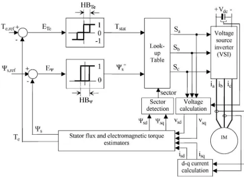
Unlike FOC, the DTC scheme as shown in Fig. 2 offers simple control structure wherein the torque and flux can be separately controlled using three- and two-level hysteresis com-parators, respectively. The output of the comparators and the stator flux angle are used to index a lookup table of optimum voltage vector as proposed by Takahashi and Noguchi [1], to determine the appropriate voltage vectors to control both torque and flux. However, the hysteresis torque controller utilized in the basic DTC structure results in two major disadvantages,
Fig. 4. CFTC.
Fig. 5. Comparison by experiment of torque control operations in (a) hysteresis-based DTC and (b) DTC-CSF-based induction motors.
namely, variable inverter switching frequency and high torque ripple. Several methods had been proposed to overcome the problems. For example, the problems were minimized by the use of variable hysteresis bands [4], dithering technique [2], controlled duty ratio cycle technique [3], [5], SVM (DTC-SVM) [6]–[8], and, recently, predictive control [16].
An attempt has been made to reduce the torque ripple by replacing the torque hysteresis controller with CFTC as shown in Fig. 4 [15]. In such a way, the simple control structure (with decoupled control structure) of hysteresis-based DTC is retained. For the sake of identification, in this paper, this scheme will be referred to as DTC-CSF. The torque error statusTstat(as shown in Fig. 4) generated from the CFTC to compensate the torque errorET ecan be described by the following equation:
Tstat=
1, forTc≥Cupper
0, forClower< Tc < Cupper
−1, forTc≤Clower
(9)
where Tc is the output of the PI controller and Cupper and
Clowerare the upper and lower triangular carriers, respectively. In order to establish CSF and, hence, reduced torque ripple, the frequency and peak to peak of the upper and lower triangular waveforms are set at fixed values. For the PI torque controller, the gain values ofKp andKiare restricted to ensure that the
absolute slope of the output signal Tc does not exceed the
absolute slope of the triangular carrier [15].
and the output torque is regulated closer to the reference with a constant and higher switching frequency.
IV. DYNAMICTORQUECONTROL
In practice, a fast dynamic torque control can be achieved by fully utilizing a dc bus voltage through an overmodulation strategy. The switching strategy to perform overmodulation mode during torque transient condition is usually referred to as dynamic overmodulation.
A. Dynamic Torque Control in Basic Hysteresis-Based DTC
It is well known that the original DTC scheme proposed by Takahashi and Noguchi [1] offers fast instantaneous torque and flux control due to the optimized voltage vector selection in controlling simultaneously both flux and torque. During large torque demand, hence large torque error, the hysteresis torque comparator produces a single status that requires an increase in torque. This means that, under this condition, no zero-voltage vectors are selected to reduce the torque. At the same time, the flux hysteresis will regulate the flux to follow the circular path using two active voltage vectors. This is similar to a condition in DTC-SVM in which the stator voltage reference vector follows the hexagonal boundary in overmodulation mode, which is the reference voltagev
[9]in Fig. 1. Since no zero-voltage vectors
are applied, rapid changes in the flux vector position and, hence, a quick dynamic torque response are achieved.
However, this method does not give the fastest dynamic torque response because one of two possible active voltage vectors switched during torque dynamic may not be optimum. To explain this, at first, an equation of torque rate in terms of applied voltage vector which was derived in [14] will be used. According to the analysis in [14], the rate of change of torque at the instant in which a voltage vector is applied is given by
dTe
dt =CΨr[Vsin(θi−θr,0)−ωΨs,0cos(θs,0−θr,0)] (10)
where C is some constant which depends on the machine parameters andV is the magnitude of the applied voltage. θi,
Fig. 6. Stator flux vector and initial stator and rotor flux vectors.
Fig. 7. Inconsistent torque slope in DTC due to the selecting different switching under dynamic condition.
θr,0, andθs,0are the stator voltage vector angle, initial rotor flux angle, and initial stator flux angle, respectively.Ψr andΨs,0 are the rotor flux magnitude and initial stator flux magnitude, respectively (these parameters are shown in Fig. 6). The second term in (10) is independent of the applied voltage vector. Thus, the maximum rate of change of torque is determined by the first term of (10) which can be written as
dT
e
dt
max = max
i {sin(θi−θr,0)}. (11)
The rotor flux angle in (11) can be assumed equivalent to the stator flux angle since the slip angular velocity, in practice, is too small. Equation (11) indicates that the fastest torque response is achieved when the voltage angle is 90◦with respect to the stator flux angle. In other words, to obtain the fastest torque response, a voltage vector that has the largest tangential component has to be selected.
The behavior of torque dynamic in DTC is investigated by applying a step change of torque reference at timet=t1 or when the stator flux vector is about to enter sector k (at αk= 0rad), as shown in Fig. 7. The output torque and stator
Fig. 8. Structure of the DTC-CSF-based induction machine with the proposed “modification of flux error status” block.
voltage vector applied (i.e., vk+1 and vk+2). According to
(11), higher torque rate can be achieved whenvk+1is switched
during the torque dynamic (as the flux vector moves from angle αk = 0toαk =π/6rad). Thus, as noticed in Fig. 7, the torque
slope under dynamic condition is steeper when vk+1 is used
(or flux increases) than the slope when vk+2 is switched (or
flux decreases). The figure shows that the basic DTC may not give the fastest torque dynamic response sincevk+2is switched
more often as the flux vector approaches toward the middle of the sector.
It should be noted that the identification of the optimized voltage vector (between two possible voltages) to achieve the fastest dynamic torque response depends on flux position. In fact, if sector k is subdivided into subsectors, (i) and (ii) based on (12), vectorvk+1will result in a higher torque slope
throughout subsector (i) and vk+2 will give a higher torque
slope throughout subsector (ii)
0≤αk < π/6rad, for subsector(i)
π/6≤αk < π/3rad, for subsector(ii). (12)
B. Proposed Dynamic Torque Control
In the proposed dynamic overmodulation method, the most optimized voltage vector that produces the highest rate of change of torque is switched and held (instead of selecting two active voltage vectors) during torque dynamic to achieve the fastest dynamic torque control. As discussed in the previous section, if sectorkis considered, this would be vectorvk+1in
subsector (i) and vectorvk+2in subsector (ii). Fig. 8 shows the
structure of the DTC-CSF-based induction machine with the proposed modification of the flux error status. Notice that all components of the hysteresis-based DTC scheme are retained, except for the inclusion of the “modification of flux error status” block which is responsible to perform the dynamic overmodulation mode. The selection of the optimized voltage vector to give the fastest torque response can be simply done by modifying the flux error status(Ψ+
s)to a new flux status(Ψ−s)
before it is being fed to the lookup table. The “modification of flux error status” block and, hence, the proposed dynamic
over-Fig. 9. Proposed digital outputs in the modified flux error status correspond to the optimized voltage vectors for every subsector in each sector.
Fig. 10. Difference in stator flux trajectory performed in (a) the basic hysteresis-based DTC as proposed in [1], (b) the method proposed in [14], and (c) the proposed method (as performed in complex DTC-SVM [6] and direct self-control [12]).
modulation are activated when the torque errorET e is greater
than 20% of the rated torque. On the other hand, the proposed DTC will be deactivated (operated with the conventional DTC switching operation, i.e.,Ψ−
s = Ψ+s) when the error of torque
ET ereduces to zero. In doing so, the current distortion can only
occur during torque transient which is relatively in a very short period of time.
When the “modification of flux error status” block is acti-vated, the output of this blockΨ−
s depends on the position of the
flux within a sector as shown in Fig. 9. If it is in subsector (i),
Ψ−
s = 0; hence,vk+1is selected. If it is in subsector (ii),Ψ−s = 1;vk+2is selected. The border of the sectors and subsectors
can be easily calculated using the threshold values of Ψs s,q,
denoted asΨsq,1andΨsq,2, which can be calculated as
Ψsq,1= Ψss,dtan(π/6) (13)
Ψsq,2= Ψss,dtan(π/3). (14)
C. Performance Comparison of Torque Dynamic Control
Fig. 11. Comparison on torque dynamic performance and flux magnitude control between (a) basic DTC and that in [14] and (b) basic DTC and the proposed method.
the flux is outside the hysteresis band. The proposed method, on the other hand, uses only the most optimized voltage during the torque dynamic, which can completely perform in six-step voltage; the flux is no longer constrained to the circular shape but rather is transformed into a hexagonal shape.
Some simulations were carried out to compare the perfor-mances of torque dynamic resulted from these schemes. For comparison, the switching optimization in [14] is only per-formed during torque dynamic, and each result achieved in [14] and the proposed method is plotted in a same graph with the result obtained in the basic DTC as shown in Fig. 11. Under the same test condition, it can be seen from this figure that the improvement in the proposed method is significant than that obtained in [14] with almost consistent torque slope. In this case, a step change of reference torque is applied when the motor speed is about 0.75 p.u. and the flux position is atαk =
π/4 rad (as defined in Fig. 7). The improvements achieved in [14] and the proposed method were also verified through simulation at different cases (i.e., the step change of torque is applied as the stator flux is at either one position,αk= 0,
π/12, π/6, π/4, or π/3 rad for different speed operations), as can be noticed in Fig. 12(a) and (b), respectively. In all cases, the rise time of torque is defined as the time taken for the torque to reach its target from the instant the step torque change is applied. Obviously, the proposed method results in better improvement for every case, and the improvement is significant particularly at high speeds and when the step change of torque applied as the stator flux is at around the middle part of a sector. It should also be noted that the performance of torque dynamic depends on operating conditions (i.e., dc voltage, load torque, and speed) [17], [18] and the selection of voltage vectors (which is influenced by flux position) as discussed previously.
V. IMPLEMENTATION ANDEXPERIMENTALRESULTS
To verify the feasibility of the proposed dynamic overmod-ulation scheme, a complete drive system as shown in Fig. 13 has been realized. The parameters for the DTC drives and the actual parameters of an induction motor are shown in Table II. For safety reason, the dc voltage was limited to 240 V, which means that the base speed is reduced to 570 r/min. The control
Fig. 12. Effects of stator flux positions and speed on torque dynamic perfor-mance. Comparison on torque dynamic performance between (a) the basic DTC and that in [14] and (b) the basic DTC and the proposed method.
algorithm is implemented on a dSPACE 1102 and an Altera field-programmable gate array (APEX20KE). The sampling period of the DTC scheme, including the proposed dynamic overmodulation, is 55µs.
To investigate the performance of dynamic torque control, a step change of torque reference from 1.5 to 9.0 N·m has been carried out for three different schemes. For convenience of identification, these schemes are referred to as follows:
1) DTC1—conventional hysteresis-based DTC;
2) DTC2—the hysteresis-based DTC with the proposed dy-namic overmodulation strategy;
3) DTC3—the CSF-based DTC with the proposed dynamic overmodulation strategy.
Based onΨs dandΨ
s
q, a step change in the torque reference
is introduced atαk=π/24rad (subsector (i) within sector 2)
and at αk=π/6 rad (subsector (ii) within sector 2). To
make the comparisons fair, the dynamic torque control in these three DTC schemes was performed under the same load torque condition so that the rotor speed operated at around 410 r/min.
Fig. 13. Complete drive system. (a) Picture of the experimental setup. (b) Functional block diagram of the experimental setup.
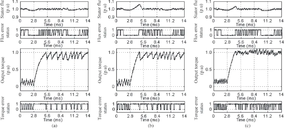
Fig. 14. Comparison by experiment of dynamic torque performance between (a) DTC1, (b) DTC2, and (c) DTC3, when a dynamic torque control occurs as the stator flux position is atαk=π/24rad (as the flux is about to enter sector 2).
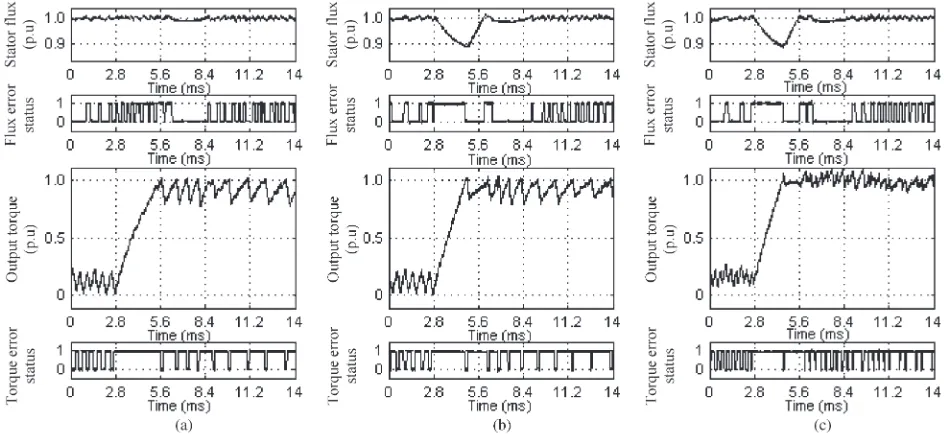
(Figs. 14 and 15), we also notice that the output torque is regulated closer to the reference with DTC3. Thus, DTC3 is the best scheme among the three schemes as it offers the fastest torque response and reduced torque ripple.
The effect of the proposed overmodulation on the stator flux locus for the two different stator flux positions can be seen from the experimental results as shown in Figs. 16 and 17. For the purpose of comparing the effect, only DTC1 and DTC2 were tested as DTC3 is actually performed in the same manner with DTC2 in selecting the voltage vector during torque dynamic at particular flux positions. The shape and, hence, the magnitude of the stator flux are affected since a single voltage vector is switched during the dynamic overmodulation. When the torque dynamic occurs in subsector (i), a single voltage vector that produces the fastest torque response is selected. This vector also increases the flux, causing the flux locus to deviate from the circular locus momentarily as shown in Fig. 16. On the other
hand, when the torque dynamic occurs in subsector (ii), a single voltage vector that gives the fastest torque response and, at the same time, reduces the flux is selected. This is indicated by the stator flux locus shown in Fig. 17. For both cases, the deviation in the flux locus from the circular locus occurs momentarily during the torque dynamic.
It is quite interesting to observe the behavior of motor currents as the flux magnitude is suddenly distorted due to the proposed switching strategy during torque dynamic condition. Fig. 18 shows the behavior of motor currents in DTC2 when the torque dynamic control is applied at αk=π/24rad and
αk=π/6rad. As can be seen from the figures, the three-phase
Fig. 15. Comparison by experiment of dynamic torque performance between (a) DTC1, (b) DTC2, and (c) DTC3, when a dynamic torque control occurs as the stator flux position is atαk=π/6rad (as the flux is about the middle of sector 2).
Fig. 16. Comparison of stator flux locus obtained in (a) DTC1 and (b) DTC2 (for one complete flux wave cycle) when a dynamic torque condition occurs at αk=π/24rad.
Fig. 17. Comparison of stator flux locus obtained in (a) DTC1 and (b) DTC2 (for one complete flux wave cycle) when a dynamic torque condition occurs at αk=π/6rad.
VI. CONCLUSION
A simple dynamic overmodulation to achieve the fastest dy-namic torque response in a DTC-CSF-based induction machine has been proposed. An optimized voltage vector that produces the highest rate of change of torque is switched and held so that the fastest dynamic torque response can be achieved. The selection of the optimized voltage vector is simply obtained
Fig. 18. Behavior of motor currents when the flux magnitude suddenly distorted due to the proposed switching strategy as the dynamic torque occurs at (a)αk=π/6rad and (b)αk=π/24rad.
by modifying the flux error status before it is being fed to the lookup table. The main benefit of the proposed method is its simplicity and, at the same time, is able to reduce the torque ripple and produce the fastest dynamic torque response (with six-step mode). The dynamic overmodulation is achieved without the need of a space vector modulator.
REFERENCES
[1] I. Takahashi and T. Noguchi, “A new quick-response and high-efficiency control strategy of an induction motor,”IEEE Trans. Ind. Appl., vol. IA-22, no. 5, pp. 820–827, Sep. 1986.
[2] T. Noguchi, M. Yamamoto, S. Kondo, and I. Takahashi, “Enlarging switching frequency in direct torque-controlled inverter by means of dithering,” IEEE Trans. Ind. Appl., vol. 35, no. 6, pp. 1358–1366, Nov./Dec. 1999.
[3] S. Mir and M. E. Elbuluk, “Precision torque control in inverter-fed induc-tion machines using fuzzy logic,” inProc. 26th Annu. IEEE PESC, 1995, vol. 1, pp. 396–401.
[4] J.-K. Kang, D.-W. Chung, and S.-K. Sul, “Direct torque control of induc-tion machine with variable amplitude control of flux and torque hysteresis bands,” inProc. Int. Conf. IEMD, 1999, pp. 640–642.
[6] A. Tripathi, A. M. Khambadkone, and S. K. Panda, “Dynamic control of torque in overmodulation and in the field weakening region,”IEEE Trans. Power Electron., vol. 21, no. 4, pp. 1091–1098, Jul. 2006.
[7] D. Casadei, G. Serra, A. Tani, L. Zarri, and F. Profumo, “Performance analysis of a speed-sensorless induction motor drive based on a constant-switching-frequency DTC scheme,”IEEE Trans. Ind. Appl., vol. 39, no. 2, pp. 476–484, Mar./Apr. 2003.
[8] C. Lascu, I. Boldea, and F. Blaabjerg, “A modified direct torque control for induction motor sensorless drive,”IEEE Trans. Ind. Appl., vol. 36, no. 1, pp. 122–130, Jan./Feb. 2000.
[9] T. G. Habetler, F. Profumo, M. Pastorelli, and L. M. Tolbert, “Direct torque control of induction machines using space vector modulation,”
IEEE Trans. Ind. Appl., vol. 28, no. 5, pp. 1045–1053, Sep./Oct. 1992. [10] G. Griva, T. G. Habetler, F. Profumo, and M. Pastorelli, “Performance
evaluation of a direct torque controlled drive in the continuous PWM-square wave transition region,”IEEE Trans. Power Electron., vol. 10, no. 4, pp. 464–471, Jul. 1995.
[11] A. M. Khambadkone and J. Holtz, “Compensated synchronous PI current controller in overmodulation range and six-step operation of space-vector-modulation-based vector-controlled drives,”IEEE Trans. Ind. Electron., vol. 49, no. 3, pp. 574–580, Jun. 2002.
[12] M. Depenbrock, “Direct self-control (DSC) of inverter-fed induction machine,”IEEE Trans. Power Electron., vol. 3, no. 4, pp. 420–429, Oct. 1988.
[13] H. Mochikawa, T. Hirose, and T. Umemoto, “Overmodulation of voltage source PWM inverter,” inProc. JIEE Ind. Soc. Conf., 1991, pp. 466–471. [14] S. A. Zaid, O. A. Mahgoub, and K. A. El-Metwally, “Implementation of a new fast direct torque control algorithm for induction motor drives,”IET Elect. Power Appl., vol. 4, no. 5, pp. 305–313, May 2010.
[15] N. R. N. Idris and A. H. M. Yatim, “Direct torque control of induction machines with constant switching frequency and reduced torque ripple,”
IEEE Trans. Ind. Electron., vol. 51, no. 4, pp. 758–767, Aug. 2004. [16] J. Beerten, J. Verveckken, and J. Driesen, “Predictive direct torque control
for flux and torque ripple reduction,”IEEE Trans. Ind. Electron., vol. 57, no. 1, pp. 404–412, Jan. 2010.
[17] D. Casadei, G. Serra, and A. Tani, “Analytical investigation of torque and flux ripple in DTC schemes for induction motors,” inProc. 23rd IEEE IECON, 1997, vol. 2, pp. 552–556.
[18] J. W. Kang and S. K. Sul, “Analysis and prediction of inverter switching frequency in direct torque control of induction machine based on hystere-sis bands and machine parameters,”IEEE Trans. Ind. Electron., vol. 48, no. 3, pp. 545–553, Jun. 2001.
Auzani Jidin(M’07) received the B.Eng. degree and the M.Eng. degree in power electronics and drives from the Universiti Teknologi Malaysia, Johor, Skudai, Malaysia, in 2002 and 2004, respectively, where he is currently working toward the Ph.D. degree.
He is a Lecturer at the Universiti Teknikal Malaysia Melaka (UTeM), Durian Tunggal, Malaysia. He is currently with the Department of Power Electronics and Drives, Faculty of Electrical Engineering (FKE), UTeM. His research interests include the fields of power electronics, motor drive systems, field-programmable gate arrays, and digital signal processing applications.
Nik Rumzi Nik Idris(M’97–SM’03) received the B.Eng. degree in electrical engineering from the University of Wollongong, Wollongong, Australia, in 1989, the M.Sc. degree in power electronics from the University of Bradford, Bradford, U.K., in 1993, and the Ph.D. degree from the Universiti Teknologi Malaysia (UTM), Johor, Skudai, Malaysia, in 2000.
He was a Visiting Research Associate at The University of Akron, Akron, OH, in 2002. He is cur-rently an Associate Professor at UTM. His research interests include ac drive systems and digital signal processing applications in power electronic systems.
Dr. Idris is an Administrative Committee member of the Industry Appli-cations Society/Power Electronics Society/Industrial Electronics Society Joint Chapter of the IEEE Malaysia Section.
Abdul Halim Mohamed Yatim (M’89–SM’01) received the B.Sc. degree in electrical and elec-tronic engineering from Portsmouth Polytechnic, Portsmouth, U.K., in 1981, and the M.Sc. and Ph.D. degrees in power electronics from the University of Bradford, Bradford, U.K., in 1984 and 1990, respectively.
Since 1982, he has been a Member of the Fac-ulty of Electrical Engineering, Universiti Teknologi Malaysia, Johor, Skudai, Malaysia, where he is cur-rently a Professor and the Dean. In 1993, he was a Visiting Scholar at the Virginia Power Electronics Center, Virginia Polytech-nic Institute and State University, Blacksburg. During 1994–1995, he was a Commonwealth Fellow at Heriot-Watt University, Edinburgh, U.K. His areas of research interest include power quality, renewable/alternative energy, power electronic applications, and drives.
Dr. Yatim is a Fellow of the Institution of Engineers Malaysia and a Registered Professional Engineer with the Malaysian Board of Engineers. He was the first Chapter Chair of the Malaysian Section of the IEEE Industrial Electronics/Industry Applications/Power Electronics Joint Societies formed in 2003.
Tole Sutikno(M’07) received the B.Eng. degree in electrical engineering from Diponegoro University (UNDIP), Semarang, Indonesia, in 1999, and the M.Eng. degree in power electronics from Gadjah Mada University (UGM), Yogyakarta, Indonesia, in 2004. He is currently working toward the Ph.D. degree in the Department of Energy Conversion, Fac-ulty of Electrical Engineering, Universiti Teknologi Malaysia, Johor, Skudai, Malaysia.
Since 2001, he has been a Lecturer in the Elec-trical Engineering Department, Universitas Ahmad Dahlan, Yogyakarta. His research interests include the fields of power elec-tronics, motor drive systems, and field-programmable gate array applications.
Malik E. Elbuluk(S’79–M’79–SM’97) received the B.Sc. degree (with honors) in electrical engineering from the University of Khartoum, Khartoum, Sudan, in 1976, and the M.S., E.E., and D.Sc. degrees in electrical engineering from the Massachusetts Insti-tute of Technology, Cambridge, in 1980, 1981, and 1986, respectively.
He was with the faculty of the Department of Electrical and Computer Engineering and the Elec-tric Power Research Center, North Carolina State University, Raleigh, from 1986 to 1989. He was a Summer Research Fellow at the Lewis Research Center, National Aeronautics and Space Administration (NASA), Cleveland, OH, from 1991 to 2010. His work at NASA included alternative energy systems, low-temperature electron-ics for space missions, modeling and simulation of Space Station Freedom, power by wire, power electronic building blocks, and the starter/generator for aircraft engines and sensorless control of electromechanical actuators for the more electric aircraft. He is currently a Professor at The University of Akron, Akron, OH, where he has been since 1989. His teaching and research interests include the areas of power electronics, electric machines, control systems, fuzzy logic, and neural networks.
Prof. Elbuluk actively publishes and reviews papers for IEEE conferences and TRANSACTIONSand has organized and chaired a number of sessions for the IEEE Power Electronics Society, the IEEE Industry Applications Society, and the IEEE Industrial Electronics Society. He was an Associate Editor for the IEEE TRANSACTIONS ONPOWERELECTRONICSand is currently the Vice Chair of the Manufacturing Systems Development and Applications Department for the IEEE TRANSACTIONS ON INDUSTRY APPLICATIONS


![Fig. 10.Difference in stator flux trajectory performed in (a) the basichysteresis-based DTC as proposed in [1], (b) the method proposed in [14], and(c) the proposed method (as performed in complex DTC-SVM [6] and directself-control [12]).](https://thumb-ap.123doks.com/thumbv2/123dok/582840.69330/5.594.42.297.75.243/difference-trajectory-performed-basichysteresis-proposed-proposed-performed-directself.webp)
![Fig. 12.Effects of stator flux positions and speed on torque dynamic perfor-mance. Comparison on torque dynamic performance between (a) the basic DTCand that in [14] and (b) the basic DTC and the proposed method.](https://thumb-ap.123doks.com/thumbv2/123dok/582840.69330/6.594.315.550.69.358/effects-positions-dynamic-comparison-dynamic-performance-dtcand-proposed.webp)