JPE 11-2-5
Extending Switching Frequency for Torque Ripple
Reduction Utilizing a Constant Frequency Torque
Controller in DTC of Induction Motors
Auzani Jidin
†, Nik Rumzi Nik Idris
∗, Abdul Halim Mohd Yatim
∗, Tole Sutikno
∗∗, and Malik E. Elbuluk
∗∗∗ †Dept. of Power Electronics and Drives, FKE, Universiti Teknikal Malaysia Melaka, Malaysia∗Dept. of Energy Conversion, FKE, Universiti Teknologi Malaysia, Malaysia ∗∗Dept. of Electrical Engineering, Universitas Ahmad Dahlan, Indonesia
∗∗∗Dept. of Electrical Engineering, University of Akron, USA
Abstract
Direct torque control (DTC) of induction machines is known to offer fast instantaneous torque and flux control with a simple control structure. However, this scheme has two major disadvantageous, namely, a variable inverter switching frequency and a high torque ripple. These problems occur due to the use of hysteresis comparators in conventional DTC schemes, particularly in controlling the output torque. This paper reviews the utilization of constant frequency torque controllers (CFTC) in DTC to solve these problems while retaining the simple control structure of DTC. Some extensions of the work in utilizing a CFTC will be carried out in this paper which can further reduce the torque ripple. This is particularly useful for a system which has a limited/low sampling frequency. The feasibility of a CFTC with an extended carrier frequency in minimizing the torque ripple is verified through experimental results.
Key Words: Direct Torque Control, Induction Machine, Switching Frequency, Torque Ripple Reduction
I. INTRODUCTION
The direct torque control (DTC) of induction motor drives has gained popularity in advanced motor drive applications since it offers fast instantaneous torque and flux control with simple implementation. This scheme is well known for its robustness in control as it is less dependent on machine parameters, does not require a complex field orientation block, a speed encoder and an inner current regulation loop. However, this scheme, which is based on hysteresis comparators [1], has major drawbacks namely a variable switching frequency, a large torque ripple and high sampling requirements for digital implementation.
It makes sense that a reduction in output torque ripple can be achieved when a lower band of torque hysteresis is used in order to restrict the ripple within the band. However, this cannot be realized using a microprocessor or a digital signal processor, particularly when an extreme torque slope occurs with an inappropriate band level (which is too small). Ideally,
Manuscript received Sep. 24, 2010; revised Jan. 30, 2011 † Corresponding Author: [email protected]
Tel: +606-555-2345, Fax: +606-555-2226/2222, UTeM
†Dept. of Power Electronics and Drives, FKE, Universiti Teknikal Malaysia
Melaka (UTeM), Malaysia
∗Dept. of Energy Conversion, FKE, Universiti Teknologi Malaysia (UTM), Malaysia
∗∗Dept. of Electrical Engineering, Universitas Ahmad Dahlan (UAD), In-donesia
∗∗∗Dept. of Electrical Engineering, University of Akron, USA
hysteresis-based operation is suitable for a discrete system which has a fast processor such that the bang-bang control can be performed the same as in analog operation. Instead of lowering the hysteresis band with a fast processor, one can inject high-frequency triangular waveforms into the errors in torque and flux [2]. This method is called the dithering technique, and it is simple and effective in minimizing torque ripple. However, it still produces an unpredictable switching frequency since the torque slopes that determine the frequency of the torque controller vary depending on the operating conditions [3], [4].
period is subdivided into three or more states, to synthesize a desired voltage vector in order to produce the minimum torque ripple. In both approaches, the application of a fast processor to compute the duty ratio or the voltage vectors for every switching period is necessary, particularly when a small sampling time is required.
Recently, the use of predictive control methods in hysteresis-based DTC has gained a considerable amount of attention, particularly due to its ability to reduce the torque ripple and as well as the switching frequency [16]-[18]. Although, a reduced torque ripple is achieved, the switching frequency still varies, since it depends on the operating conditions as well as the possible applied voltage vectors.
This paper reviews the use of constant frequency torque controllers (CFTC) in the direct torque control (DTC) of induction machines to reduce the output torque ripple with a constant switching frequency as proposed in [11]. However, it is possible to further increase the switching frequency in [11] which will result in a further reduction of the torque ripple, particularly when DTC is performed with a limited sampling frequency, i.e. a low speed processor. Some extensions of the work in utilizing CFTC in DTC will be highlighted in this paper to show that:
1) A high switching frequency to further reduce the output torque ripple can be established with a CFTC, by extend-ing the triangular carrier frequency up to one-quarter of the maximum sampling frequency achieved by a DSP. 2) With suitable PI-controller gains, excellent control of
the output torque as well as a significant reduction in the torque ripple can be achieved at the maximum triangular carrier frequency. A simple linear relationship between the input-output of the triangular carrier model (as obtained in [11]) can still be assumed and the output torque can still be regulated if an appropriate cross-over frequency is selected based on the maximum switching frequency.
An extension of the constant switching frequency is partic-ularly useful for a system which has a limited/low sampling frequency. Moreover, this paper also presents a quick guide for the design of CFTC to simplify the detailed description in [11]. The feasibility of the use of a CFTC in DTC in reducing torque ripple (at three different carrier frequencies) is verified through experimentation as well as a comparison with a conventional DTC scheme. In section II of this paper, the basic principle of DTC is briefly discussed. DTC with a CFTC is briefly explained in Section III. Section IV presents a quick guide of the design procedures for a CFTC in DTC. Section V presents the implementation and experimental results of a CFTC in DTC. Finally the conclusions are given in Section VI.
Fig. 1. Structure of basic DTC-hysteresis based induction machine.
II. BASICPRINCIPLE OFDTC
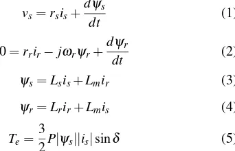
The behavior of induction machines in DTC drives can be described in terms of space vectors by the following equations written in the stator stationary reference frame:
vs=rsis+ dψs
dt (1)
0=rrir−jωrψr+ dψr
dt (2)
ψs=Lsis+Lmir (3)
ψr=Lrir+Lmis (4)
Te= 3
2P|ψs||is|sinδ (5) where P is the number of pole pairs,ωr is the rotor electric angular speed in rad./s, Ls, Lr and Lm are the motor induc-tances and δ is the angle between the stator flux linkage and the stator current space vectors. Based on (1) the ds- and qs -axis stator flux in the stationary reference frame can be written as:
ψs,ds= Z
(vs,ds−is,dsrs)dt (6a)
ψs,qs= Z
(vs,qs−is,qsrs)dt. (6b)
In terms of the switching states Sa,Sb, and Sc (which can be either 0 or 1) the voltage vectors in (6) are given by:
vs,ds=1
3Vdc(2Sa−Sb−Sc) (7a)
vs,qs=√1
3Vdc(Sb−Sc). (7b) The electromagnetic torque given in (5) can be rewritten in the ds-qs coordinates as:
Te= 3 2P(ψs,d
si
s,qs−ψs,qsis,ds). (8)
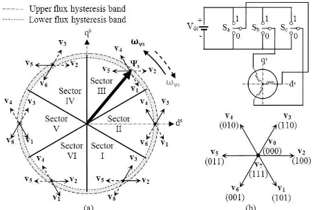
Fig. 2. Selection of the optimum inverter output voltage vectors. (a) Each sector indicates the appropriate voltage vectors. (b) Eight possible switches configuration in the three-phase VSI.
TABLE I
increased or decreased and also on the stator flux position. The decisions as to whether the torque and/or the flux need to be increased or decreased comes from the three-level and two-level hysteresis comparators for the torque and stator flux, respectively. Fig. 2 illustrates the two optimized voltage vectors in every sector, which are selected from the eight possible switch configurations, using the look-up table given in Table I [1].
Notice that in order to control the flux, two active voltage vectors are required. On the other hand, to control the torque, one active voltage vector is used to increase the torque while a zero voltage vector is used to reduce it. By limiting the torque and flux errors to within their hysteresis bands, a de-coupled control of the torque and flux is achieved.
It is well-known that the main drawbacks of hysteresis-based DTC schemes are their variable inverter switching fre-quency, high sampling requirement for digital implementation and high torque ripple. To highlight these problems, some experimental results showing output torque ripples obtained in hysteresis-based DTC at different applied sampling frequen-cies and/or torque hysteresis bands are presented as shown in Fig. 3.
For each case, the control of the torque at 6 Nm was performed under the same load torque condition so that the rotor speed operated at around 400 rpm. The nominal level of the torque hysteresis band is HBTe(0.9 Nm) and the minimum sampling time achievable using DSP is DT (55µs) (more
Fig. 3. Experimental results of control of output torque utilizing three-level hysteresis comparator (in hysteresis based-DTC). (a) Hysteresis band = 2HBTe, sampling time=2DT, (b) hysteresis band = HBTe, sampling time=DT.
information on the values of the machine and the control system parameters will be presented in Section V). From Fig. 3(a), as expected, the output torque ripple is high when the torque hysteresis band is set to twice the HBTe. Thus, the torque ripple of the hysteresis-based DTC can be reduced by reducing the hysteresis band. Fig. 3(b) shows the results of the output torque control when the torque hysteresis band reduces to HBTe. However, due to the sampling time used in Fig. 3(b) (and also in Fig. 3(a)) it is twice of the nominal DT (i.e. 110µs). This leads to incorrect voltage vector selections (where Tstat =−1) which cause rapid decreases in the output torque and hence increases in the torque ripple, as can be seen in Fig. 3(b). Therefore, to eliminate the incorrect voltage vector selections, the sampling time needs to be reduced, as demonstrated in Fig. 3(c) whereby the sampling is set to DT. As can be seen in Fig. 3(c), the output torque ripple is decreased and no active voltage vector is selected to reduce the torque.
III. DTCWITHCONSTANTFREQUENCYTORQUE CONTROLLER
Fig. 4. Constant frequency torque controller (CFTC).
Fig. 5. Typical waveforms of the constant frequency torque controller.
Fig. 5 shows the typical waveforms of a constant frequency torque controller. The torque error status Tstat generated from the constant frequency torque controller can be described by the following equation:
Tstat=
1 for Tc≥Cupper
0 for Clower<Tc<Cupper −1 for Tc≤Clower
(9)
whereTc is output of proportional-integral (PI) control while Cupper and Clower are the upper and lower triangular wave-forms, respectively. Note that, the two triangular waveforms (Cupper and Clower) are 180◦ out of phase with each other. In order to establish a constant switching frequency, the frequency and peak to peak of the upper and lower triangular waveforms are set to fixed values. It is desirable to set a high triangular waveform frequency in minimizing the output torque ripple. For a PI torque controller, the gain values of Kp and Ki are restricted to ensure that the absolute slope of the output signal,Tc does not exceed the absolute slope of the triangular waveform. This is to ensure the proper operation of the torque control at a constant switching frequency and to avoid the selection of incorrect voltage vectors, for a wide range of operating conditions.
IV. DESIGNPROCEDURE FOR ACONSTANTFREQUENCY TORQUECONTROLLER INDTC
This section presents a quick guide to designing a proper constant frequency torque controller in the DTC of induction machines. Briefly, there are three steps to obtaining the proper
Fig. 6. Generated upper triangular waveform using DSP (sampled at DTµs).
operation of a CFTC. A detailed explanation on how the related equations (as shown later) were derived and how some of the assumptions made, can be found in [11].
Step 1: Select an appropriate frequency for the triangular waveforms
It is desirable to have a large triangular frequency in order to acquire a large torque loop bandwidth and hence a faster torque response. Moreover, with a higher triangular frequency the output torque ripple will be reduced. The triangular wave-forms are generated by software sampled at the maximum sampling rate to execute the algorithms (i.e DTC including a CFTC) but limited by the DSP speed. For example, the upper triangular waveform produced by the DSP is depicted in Fig. 6, whereby DT is the sampling period of the DSP. In this particular example, a complete triangular waveform is completed in a DSP sampling time of eight.
Step 2: Determine the gain value of Kp
It must be ensured that the absolute slope of Tc does not exceed the absolute slope of the triangular waveforms, which are mainly determined by the proportional gain (Kp) of the PI controller. The absolute slope of the triangular waveform (as shown in Fig. 6) can be simply obtained as:
<absolute slope of the triangular waveform>
=
Cp−p 4DT
. (10)
According to [10]; for a positive slope of Tc, the following condition must be satisfied:
<absolute slope of the triangular waveform>
≥n−ATe+BVsψs+Kt
ωslip
d −ω + r
o
K+p (11)
meanwhile, for a negative slope, the following condition must be satisfied:
<absolute slope of the triangular waveform>
≥−ATe−K1ωr− K−p
(12)
where,
A=
1
σ τs + 1
σ τr
(13)
B= 6PLM 4σLsLr
ψs (14)
K1= 3P
2 Lm
σLsLr
Fig. 7. Averaged and linearized torque loop (as in [11]).
d=ATe−K1ωslip BVψs
s
. (16)
In (13)-(15), σ is the total leakage factor, given by (1− L2m/(LrLs)). τr andτs are the rotor and stator time constants, respectively. The termVψs
s (11) and (16) is the voltage vector magnitude, given by(2Vdc/3).
It should be noted, that the occurrence of an extreme slope of Tc (either positive or negative slope) depends on the operating conditions. Considering that the motor operates under the worst-case conditions, (i.e. the torque and flux are operated under the rated conditions), it is therefore, according to (11) (or (12)), the maximum Kp+ (or K−p) that limits the slope ofTc (or absolute slope of Tc) to its maximum. This is assumed to occur at a zero rotor speed (or at the base rotor speed) and at the rated slip. That is,ω+
r =0 for (11) andωr−is set at the base speed for (12). Thus, to ensure proper operation the proportional gain (Kp) is obtained as:
Kp=min{Kp+,Kp−}. (17) Step 3: Determine the gain value of Ki
Fig. 7 depicts a block diagram of the linearized torque loop proposed in [10]. The dashed box in Fig. 7 represents the constant frequency torque controller (CFTC). To select the gain constants of the PI controller in the torque loop, which results in a phase margin of 65◦ (or higher), the zero of the PI controller is chosen to be the same as the pole of the open-loop gain (or the pole in the torque slope transfer function). Under this condition, the integral gainKi is calculated as:
Ki=KpA. (18)
In this way, an infinite dc gain due to the presence of an integrator in the PI controller will reduce the steady state error to zero. Based on the linear control theory, the obtained values forKpandKi(from (17) and (18)), must be adjusted such that the torque loop gain crossover frequency is much smaller than the carrier frequency. For a clearer picture, the determination of the PI controller’s gain, presented in section V, will use numerical values based on the actual motor parameters given in Table II.
V. IMPLEMENTATION ANDEXPERIMENTALRESULTS The feasibility of the CFTC in DTC, in providing a constant switching frequency and a reduced torque ripple has been realized with a complete drive system as shown in Fig. 8. The control algorithm is implemented on a DSPACE 1102 and an Altera FPGA (APEX20KE). Some of the main tasks of the DTC (i.e. the look-up table and the blanking time) are imple-mented utilizing the FPGA. As a result, the DSP (DSPACE
Fig. 8. Complete drive system of the experiment set-up.
1102) is able to execute the DTC algorithm including the CFTC operation in the minimum sampling period which is 55 µs.
Based on the previous discussion, in order to obtain the maximum reduction in the torque ripple, the switching fre-quency needs to be increased. Normally this can be achieved by using a high-speed DSP system. For example, the use of the SVM technique in DTC requires a fast processor to calculate the duty cycles or the voltage vectors for every sampling period. With a small sampling period, a reduction of the output torque ripple is accomplished since more switching states are applied within a switching period [6][10][13]-[15]. This paper, on the other hand, suggests a simple method for utilizing CFTC to extend the switching frequency. By using this method, an increase in the triangular frequency can be established without requiring a reduction in the sampling period of the DSP.
To verify this, a comparison of the output torque ripple obtained from three schemes was carried out; where each of schemes performed at three different ‘triangular’ frequencies but at the same sampling period, DT=55µs. For ease of identification, these schemes are referred as:
1) DTC-CSF1-DTC with CFTC at 2.2727 kHz, 2) DTC-CSF2 - DTC with CFTC at 3.0303 kHz, 3) DTC-CSF3 - DTC with CFTC at 4.5454 kHz.
The generated upper triangular waveforms for each scheme can be illustrated as depicted in Fig. 9. For example, if we consider the case of DTC-CSF1, eight steps per cycle of the triangular are used, that is for 100 units peak-peak the corresponding vertical resolution of the triangular waveform is 25 units per step, as can be seen in Fig. 9(a). From the figure, it can also be seen that the frequency of the triangular waveform is about 2.2727 kHz and the slope of the triangular is equal to 454545.45s−1.
Fig. 9. Generated upper triangular waveforms sampled at 55µs. (a) DTC-CSF1, (b) DTC-CSF2 and (c) DTC-CSF3.
TABLE II
INDUCTIONIMACHINEPARAMETERS.
Stator resistance 5.5Ω
Rotor resistance 4.45Ω
Stator self inductance 313.9 mH Rotor self inductance 313.9 mH
Mutual inductance 299 mH
Number of poles 4
Stator flux rated 0.892 Wb
Torque rated 9 Nm
Voltage vector magnitude,Vsψs 160 V Slip rated,ωslip 9.4248
Base speed 570 rpm.
approximated crossover frequency (as shown in Fig. 9) for each scheme, are given in Table III.
Fig. 11 depicts the frequency spectrum of the phase current obtained from the experimental results for basic DTC, DTC-CSF1, DTC-CSF2 and DTC-CSF3 at speeds of 20 rad/s, 30 rad/s and 55 rad/s while the output torque was controlled to 2 Nm. It can be seen that the phase currents in schemes for DTC with CFTC (i.e. DTC-CSF1, DTC-CSF2 and DTC-CSF3) contains dominant harmonics at their respective triangular frequencies regardless of speed, unlike the hysteresis-based DTC which has a frequency spectrum that is spread out and depends on the operating speed. From this figure, it can also be seen that, a higher torque is obtained in the DTC with a proper CFTC (DTC-CSF1, DTC-CSF2 or DTC-CSF3) than that obtained in the basic DTC. Moreover, the output torque ripple in the DTC with a proper CFTC can be reduced further when a higher triangular frequency is applied. Fig. 12 shows a comparison of the of output torque ripple, from the experimental results, when a step change in the torque reference is applied, in the basic DTC, DTC-CSF1, DTC-CSF2 and DTC-CSF3. To make the comparison fair, the step torque change for each scheme was performed under the same load torque conditions so that the rotor speed operated at around 370 rpm. From the figure, it can be seen that the largest torque ripple is produced with the hysteresis-based DTC.
To reduce the torque ripple, the CFTC is utilized, and as
TABLE III
PI CONTROLLERGAINS ANDCROSSOVERFREQUENCY.
Schemes PI Controller gains Crossover freq.
Kp Ki fc(kHz)
DTC-CSF1 29 9937.5 0.719
DTC-CSF2 34.9 11925 0.86
DTC-CSF3 52.3 17887 1.3
Fig. 10. Bode plot of loop gain with PI controller for (a) DTC-CSF1, (b) DTC-CSF2 and (c) DTC-CSF3.
(a)
(b)
(c)
Fig. 11. Experimental results of phase current frequency spectrum and output torque for the basic DTC, DTC-CSF1, DTC-CSF2 and DTC-CSF3 at the speed about (a) 20 rad/s (b) 30 rad/s and (c) 55 rad/s.
mentioned earlier, the output torque can be reduced further when a higher triangular frequency is applied. Obviously, the output torque ripple in the DTC-CSF3 is greatly reduced with a constant and the highest switching frequency. The generated waveforms of the upper triangular for each different frequency (as shown in Fig. 12) can be clearly seen by using a larger scale as depicted in Fig.13.
Fig. 12. Experimental results for step response of torque in (a) DTC-hysteresis based, (b) DTC-CSF1, (c) DTC-CSF2 and (d) DTC-CSF3. (1) is output torque, (2) is reference torque, (3) is torque error, (4) is output of PI controller, (5) is upper triangular waveform, (6) is torque error status. (x-axis or time scale: 2 ms/div.)
Fig. 13. The zoomed image (zoomed area indicated by ‘↔) of the waveforms of upper triangular and output of PI controller for (a) CSF1, (b) DTC-CSF2 and (c) DTC-CSF3, corresponds the results obtained in Fig. 12 (b),(c) and (d). (Time scale: 1 ms/div.)
torque and the speed profiles are comparable to those of the hysteresis-based DTC, but, with the added advantages of a reduced torque ripple and a constant switching frequency.
VI. CONCLUSIONS
This paper suggests a simple way to provide a high con-stant switching frequency and hence reduce torque ripple, by replacing the torque hysteresis controller with a CFTC in the basic DTC structure. The paper showed that with a limited sampling frequency, the carrier frequency utilized in a CFTC can be increased further to its maximum (which is at one-quarter of the maximum sampling frequency). Some experimental results were presented to show that a significant reduction in the output torque ripple can be achieved with the proper PI-controller gains and the proper selection of a triangular frequency in CFTC.
ACKNOWLEDGMENT
The authors would like to thank the Ministry of Sci-ence, Technology and Innovation (MOSTI), the Univer-siti Teknikal Malaysia Melaka (UTeM) and the UniverUniver-siti Teknologi Malaysia (UTM) for providing the funding and sponsorship for this research.
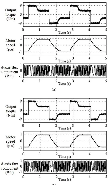
(a)
(b)
Fig. 14. Experimental results of output torque, motor speed and d-axis flux component for a square-wave speed reference for (a) the basic DTC and (b) DTC-CSF2 based induction machine drives.
REFERENCES
[1] I. Takahashi and T. Noguchi, “A new quick-response and high-efficiency control strategy of an induction motor,”IEEE Trans. Ind. Appl., Vol. IA-22, No. 5, pp. 820-827, Sep. 1986.
[2] T. Noguchi, M. Yamamoto, S. Kondo, and I. Takahashi, “Enlarging switching frequency in direct torque-controlled inverter by means of dithering,”IEEE Trans. Ind. Appl., Vol. 35, Np. 6, pp. 1358-1366, Nov./ Dec. 1999.
[3] J. W. Kang and S. K. Sul, “Analysis and prediction of inverter switching frequency in direct torque control of induction machine based on hysteresis bands and machine parameters,”IEEE Trans. Ind. Eletron., Vol. 48, No. 3, pp. 545-553, Jun. 2001.
[4] D. Casadei, G. Serra, and A. Tani, “Analytical investigation of torque and flux ripple in DTC schemes for induction motors,” in proc. of IECON 97, Vol. 2, pp. 552-556, 1997.
[5] J. K. Kang, D. W. Chung, and S. K. Sul, “Direct torque control of induction machine with variable amplitude control of flux and torque hysteresis bands,”International Conference in Electric Machines and Drives, pp. 640-642, 1999.
[6] T. G. Habetler, F. Profumo, M. Pastorelli, and L. M. Tolbert, “Direct torque control of induction machines using space vector modulation,” IEEE Trans. Ind. Appl.Vol. 28, No. 5, pp. 1045-1053, Sep./Oct. 1992. [7] J. K. Kang and S. K. Sul, “Torque ripple minimization strategy for direct torque control of production motor,”IAS Annual Meeting in Industry Applications Conference, Vol.1, pp. 438-443, 1998.
[8] S. Mir and M. E. Elbuluk, “Precision torque control in inverter-fed induction machines using fuzzy logic,”26th Annual IEEE Power
machines with constant switching frequency and reduced torque ripple,” IEEE Trans. Ind. Eletron., vol. 51, No. 4, pp. 758-767, Aug. 2004. [12] A. Jidin, M. Basar, A. Noordin, N. Idris, and A. Yatim, “A
wide-speed high torque capability utilizing overmodulation strategy in DTC of induction machines with constant switching frequency controller,” International Conference on Power Electronics and Drive Systems, pp. 649-654, 2009.
[13] C. Lascu, I. Boldea, and F. Blaabjerg, “A modified direct torque control for induction motor sensorless drive,”IEEE Trans. Ind. Appl., Vol. 36, No. 1, pp. 122-130, Jan./Feb. 2000.
[14] A. Tripathi, A. M. Khambadkone, and S. K. Panda, “Torque ripple analysis and dynamic performance of a space vector modulation based control method for AC-drives,”IEEE Trans. Power Eletron., Vol. 20, No. 2, pp. 485-492, Mar. 2005.
[15] Y.-S. Lai and J.-H. Chen, “A new approach to direct torque control of induction motor drives for constant inverter switching frequency and torque ripple reduction,”,IEEE Trans. Energy Convers., Vol. 16, No. 3, pp. 220-227, Sep. 2001.
[16] G. Papafotiou, J. Kley, K. G. Papadopoulos, P. Bohren, and M. Morari, “Model predictive direct torque control;part II: implementation and experimental evaluation,”IEEE Trans. Ind. Eletron., Vol. 56, No.6, pp. 1906-1915, Jun. 2009.
[17] J. Beerten, J. Verveckken, and J. Driesen, “Predictive direct torque control for flux and torque ripple reduction,”IEEE Trans. Ind. Eletron., Vol. 57, No.1, pp. 404-412, Jan. 2010.
[18] T. Geyer, G. Papafotiou, and M. Morari, “Model predictive direct torque control;part I: concept, algorithm, and analysis,” IEEE Trans. Ind. Eletron., Vol. 56, No.6, pp. 1894-1905, Jun. 2009.
Auzani Jidinreceived his B.Eng. and M.Eng. in Power
Electronics and Drives from the Universiti Teknologi Malaysia (UTM), Johor, Malaysia in 2002 and 2004, respectively. He is currently pursuing his PhD at the same university. He is a Lecturer in the Department of Power Electronics and Drives, Faculty of Electri-cal Engineering, Universiti Teknikal Malaysia Melaka (UTeM), Malaysia. His research interests include the field of power electronics, motor drive systems, field programmable gate arrays (FPGA) and digital signal processing (DSP) appli-cations.
Nik Rumzi Nik Idrisreceived his B.Eng. in Electrical
Engineering from the University of Wollongong, Wol-longong, Australia, his M.Sc. in Power Electronics from Bradford University, Bradford, West Yorkshire, U.K., and his Ph.D. from the Universiti Teknologi Malaysia, Skudai, Malaysia, in 1989, 1993, and 2000, respectively. He was a Visiting Research Associate at the University of Akron, Akron, OH, in 2002. Currently, he is an Asso-ciate Professor at the Universiti Teknologi Malaysia, and an Administrative Committee Member of the Industry Applications Societies
Electrical and Electronic Engineering from Portsmouth Polytechnic, Portsmouth, U.K., in 1981, and his M.Sc. and Ph.D. in Power Electronics from Bradford Univer-sity, Bradford, U.K., in 1984 and 1990, respectively. Since 1982, he has been a member of the faculty at the Universiti Teknologi Malaysia, Johor, Malaysia, where he is currently a Professor and the Deputy Dean of the Faculty. He has been involved in several research projects in the areas of power electronic applications and drives. He was a
Commonwealth Fellow from 19941995 at Heriot-Watt University, Edinburgh, U.K., and a Visiting Scholar at the Virginia Power Electronics Center, Virginia Polytechnic Institute and State University, Blacksburg, in 1993. Dr. Yatim is a Corporate Member of the Institution of Engineers Malaysia. He is a Registered Professional Engineer with the Malaysian Board of Engineers. He currently holds the Interim Chapter Chair of the Malaysian Section of the IEEE Industrial Electronics/Industry Applications/Power Electronics Joint Societies.
Tole Sutiknoreceived his B.Eng. in Electrical
Engineer-ing from Diponegoro University (UNDIP), Semarang, Indonesia and his M.Eng. in Power Electronics from Gadjah Mada University UGM), Yogyakarta, Indonesia, in 1999 and 2004, respectively. Since 2001 he has been a Lecturer in Electrical Engineering Department, Universitas Ahmad Dahlan (UAD), Yogyakarta, Indone-sia. Currently, he is pursuing his PhD. in the Energy Conversion Department, Universiti Teknologi Malaysia (UTM), Johor, Malaysia. His research interests include the field of power electronics, motor drive systems and field programmable gate array (FPGA) applications.
Malik E. Elbulukreceived his B.Sc. (with honors) from