10
COMPARISON PERFORMANCE OF INDUCTION MOTOR
USING SVPWM AND HYSTERESIS CURRENT
CONTROLLER
1
FIZATUL AINI PATAKOR, 2MARIZAN SULAIMAN, 3ZULKIFILIE IBRAHIM
Faculty of Electrical Engineering, Universiti Teknikal Malaysia, Melaka, Malaysia.
E-mail: [email protected]
ABSTRACT
This paper presents the comparative performances of three phase induction motors using space vector pulse width modulation (SVPWM) and hysteresis current controller. An indirect field orientation is applied to ensure decoupling control between torque and flux of the induction motor. The hysteresis current controller is built in with PI speed controller and three hysteresis current bands while the SVPWM system is embedded with the two control loops, the inner current control loop and the outer speed control loop using PI controller. Both systems were run and tested using MATLAB/SIMULINK software. The simulation results demonstrate that the SVPWM can improve the quality of the stator current and reduce the torque ripple while maintaining the other performance characteristics of the system.
Keywords: Indirect Field Oriented, Space Vector Pulse Width Modulation (SVPWM), Hysteresis Current
Controller
1. INTRODUCTION
At the present time, the field oriented control (FOC) technique is the widespread used in high performance induction motor drives [1, 2]. It allows, by means a co-ordinate transformation, to decouple the electromagnetic torque control from the rotor flux, and hence manage induction motor as DC motor. In this technique, the variables are transformed into a reference frame in which the dynamic behave like DC quantities. The decoupling control between the flux and torque allows induction motor to achieve fast transient response. Therefore, it is preferred used in high performance motor applications.
Nevertheless the performance of the output voltage of inverter that fed induction motor system is mainly determined by pulse width modulation (PWM) strategy. The simple implementation is use current control based on hysteresis current controller. With this method, fast response current loop will be obtained and knowledge of load parameter is not required. However this method can cause variable switching frequency of inverter [3] and produce undesirable harmonic generation [4, 5]. Another method of PWM that have become popular and received great interest by researcher is SVPWM [5-7]. This technique have better dc bus utilization [7] and easy for digital implementation [8].This paper presents a comparative performance
of SVPWM towards the traditional hysteresis current controller to control high performance induction motor incorporated with indirect field orientation technique. The modeling and simulation of SVPWM system of induction motor is performed, the principle and algorithm is analyzed. This report is organized as follows. The dynamic model of induction motor is introduced in section 2, and then the Space Vector PWM based indirect field orientated control is presented in section 3. The comparison performance of the system is presented in simulation result in section 4 and finally some concluding remarks are stated in the last section.
2. DYNAMIC MODEL OF INDUCTION
MOTOR
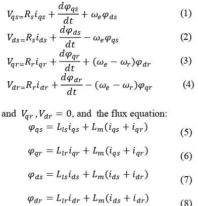
Three phase squirrel cage induction motor in synchronously rotating reference frame can be represent as Fig 1,[9]
11 b)
Fig 1:Equivalent circuit of induction motor in synchronous rotating reference frame; a) q-axis circuit
b) d-axis circuit
Where the voltage equation is:
(1)
the stator and rotor resistances, , denotes
stator and rotor inductances, whereas is the
mutual inductance. The electromagnetic torque equation is
(9)
where P, denote the pole number of the motor. If the vector control is fulfilled, the q component of
the rotor field would be zero. Then the
electromagnetic torque is controlled only by q-axis stator current and becomes:
(10)
3. SVPWMBASEDINDIRECTFIELD
ORIENTEDCONTROL
Fig. 2 (a) and (b) shows the block diagram of indirect field oriented controlled of three phase induction motor with hysteresis current controller
and SVPWM.The flux command indicates the
right rotor flux command for every speed reference within the nominal value. From this the d-axis
current reference , can be calculate using
equation (11)
(11)
The rotor speed is compared to rotor speed
command and the resulting error is process in
the controller. The controller generates the q-axis
reference current . For hysteresis current
controller in Fig. 2(a), both stator reference current in d-axis and q-axis are converted to three phase stationary reference frame through Inverse Park Transformation and compared to the current from the feedback of the motor. Then the current errors are fed to hysteresis current controllers which generate switching signal for the voltage source inverter.
While for SVPWM technique in Fig 2(b), both reference current in d-axis and q-axis is compared from the feedback from the motor current through Clark and Park Transformation. From the respective error the voltage command signal is generated through PI controller and converted to three phase voltage and fed to SVPWM block. The SVPWM can be implemented by:
• Determine , , and angle
• Determine time duration T1, T2 and T0
• Determine the switching time of each
transistor
In SVPWM block, the three phase voltage is transform into d-q axis using (12)
√ √
(12)
12 (a)
(b)
Fig 2 Indirect field oriented control (a) Hysteresis current control configuration, (b) SVPWM configuration
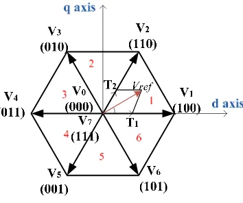
13 It is show that there are six voltage vectors that can be selected to apply to the motor. The reference and angle of respective sector can be obtain as
(13)
(14)
And switching time duration at any sector is as
√ (15)
√ (16)
(17)
where N is a sector from 1 to 6, is angle between
° to 6 °and Tz= 1/fz, sampling frequency.
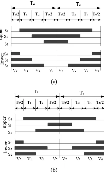
SVPWM switching pattern for sector 1 and sector 6 is shown in Fig. 4 and switching time at any sector sequence is summarized in Table 1. From this table a mathematical equation is built in function block in SIMULINK to generate a SVPWM waveform
up
Fig 4 Switching pattern for (a) sector 1(b) sector 6
TABLEI
SWITCHING TIME CALCULATION AT EACH SECTOR
Sector Upper Switches
(S1, S3, S5)
Lower Switch (S4,S6, S2)
4. SIMULATIONRESULT
Simulation has been carried out by using MATLAB/SIMULINK for 1.5KW, 1440 rpm three phase inductions motor which has parameter as follows:
Rs, stator resistance, 7.83Ω
Rr, rotor resistance, 7.55Ω
Ls, stator inductance, 0.4751H
Lr, stator inductance, 0.4751H
Lm, magnetizing inductance, 0.4535H
J, moment of inertia, 0.06Kg m2 P, number of poles,4
14 (a)
(b)
(c)
Fig 5 Simulation result of SVPWM (a) Vd and Vq voltage (b) Sector (c) operating time
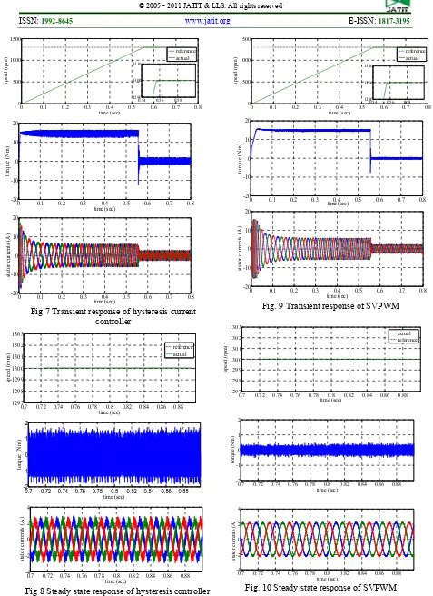
Fig. 7 shows the starting transient with no load applied and Fig. 8 show the steady state response of hysteresis current controller. While Fig. 9 and Fig. 10 shows the result for SVPWM with the same condition. It can be observe that the ripple in torque and stator currents are more during the steady state in hysteresis current controller and can be reduce with the SVPWM method.
It also shows that the torque ripple in steady state condition is ±1.8 with hysteresis current controller, and it reduced to ±0.6 with SVPWM technique. Also stator currents show improvement with SVPWM technique, that the current are almost pure sinusoidal.
(a)
(b)
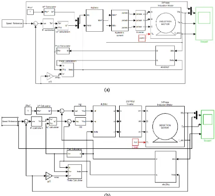
Fig 6 Overall simulation in SIMULINK (a) Hysteresis current controller (b) SVPWM
0.7 0.71 0.72 0.73 0.74 0.75 0.76 0.77 0.78 0.79 0.8
0 2 4 6
S
ec
to
r-N
0.7 0.72 0.74 0.76 0.78 0.8 -1
-0.5 0 0.5 1
O
p
er
at
in
g
t
im
e
(s
ec
15 Fig 7 Transient response of hysteresis current
controller
Fig 8 Steady state response of hysteresis controller
Fig. 9 Transient response of SVPWM
Fig. 10 Steady state response of SVPWM
0 0.1 0.2 0.3 0.4 0.5 0.6 0.7 0.8
0.54 0.56 0.58 1290
1300 1310
0.54 0.56 0.58 1290
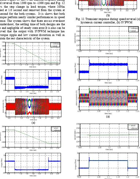
16 Figure 11 - Fig. 12 illustrate the comparative performance of speed response, torque developed and stator current for induction motor with hysteresis current controller and using SVPWM technique in various condition. Figure 11 shows the transient response during speed reversal from 1300 rpm to -1300 rpm and Fig. 12 shows the step change in load torque, where 10Nm applied at 1.0 second and removed from the system at 1.2 second for the both systems. It is shows that both technique perform nearly similar performances in speed response. The system shows that there are no overshoot and undershoot, the settling time of both designs are the same and negligible of steady state error.It is also can be observed that the output with SVPWM technique has low torque ripple and low current distortion as well as maintain the rest characteristic of the system.
(a)
(b)
Fig. 11 Ttransient response during speed reversal (a) hysteresis current controller, (b) SVPWM
17 (b)
Fig. 12 Step change in load (a) hysteresis current controller, (b) SVPWM
5. CONCLUSION
In this paper, an indirect field oriented control of three phase induction motor using hysteresis current band and SVPWM technique has done using MATLAB/SIMULINK. The comparative performances between both techniques were presented. From the simulation results, SVPWM technique gives better performances in elimination of the stator current harmonics and reduction of the torque ripple while maintaining the other characteristic of the system.
REFRENCES:
[1] G. Ramadas, t. Thyagarajan, and V. Subrahmanyam, “Robust Performance of
Induction Motor Drives,” International
Journal of Recent Trends in Engineering, vol. 1, no. 3, 2009.
[2] D. Alfonso., G. Gianluca., and M. Ignazio., “A sliding mode control technique for direct speed control of induction motor
drives,” Power Electronics Specialist
Conference, vol. 3, pp. 1106-1111, 2000.
[3] N. R. Reddy, T. B. Reddy, J. Amarnath et
al., “Simplified SVPWM Algorithm for
Vector Controlled Induction Motor Drive Using the Concept of Imaginary Switching
Times,” International Journal of Recent
Trends in Engineering, vol. Vol 2, no. No.
5, pp. 288-291, 2009.
[4] P. Alkorta, O. Barambones, A. J. Garrido et
al., “SVPWM Variable Structure Control
of Induction Motor Drives ” Industrial
Electronics ISIE, pp. 1195-1200, 2007.
[5] Z. Li, and L. Hefei, “Modelling and Simulation of SVPWM Control System of Induction Motor in Electric Vehicle,” Proceeding of the IEEE International
Conference on Automation and Logistics,
pp. 2026-2030, September 2008, 2008.
[6] D. Rathnakumar, J. LakshmanaPerumal,
and T. Srinivasan, “A new software implementation of space vector PWM,”
IEEE SoutheastCon, 2005. Proceedings,
pp. 131-136, 2005.
[7] R. Swamy, and P. Kumar, “Speed Control
of Space Vector Modulated Inverter Driven
Induction Motor,” Proceedings of the
International MultiConference of
Engineers and Computer Scientists, vol. 2,
2008.
[8] A. Anugrah, M. Sulaiman, and R. Omar,
“Space Vector Analysis in Electrical Drive for Single Phase Induction Motor Using Matlab/Simulink ” Journal of Theoretical
and Applied Information Technology, pp.
710-719, 2005.
[9] B. K. Bose, Modern Power Electronics and
AC Drives, p.^pp. 63-70: Prentice Hall,