PROJECT COMPLETION REPORT
FOR
(SHORT TERM) RESEARCH GRANT
DEVELOPMENT OF STEREO VISION SENSOR AND
DISTANCE ESTIMATION FOR COMPUTER VISION
APPLICATION (DE-CV)
Principal Researcher : SHAMSUL FAKHAR BIN ABD GANI Co-Researchers : 1. Rostam Affendi bin Hamzah (FTK)
2. Khairul Azha bin A Aziz (FTK) 3. Ahmad Fauzan bin Kadmin (FTK) 4. Zul Atfyi Fauzan bin Mohamed Napiah
(FKEKK)
Project Code No. : PJP/2012/(28B)/S01031 Report Submission Date : 1 July 2013
Department of Electronic & Computer
Engineering Technology (JTKEK)
Abstract
Stereo vision system is a practical method for depth gathering of objects and features in an environment. The purpose of this project is to design and develop a tool for stereo vision system with horizontal configuration and can estimate the range of obstacles or objects detected by stereo vision sensor. The application in this project is using autonomous guided vehicle as a platform to get the result of stereo vision system capabilities. The objectives are to optimize and to test the algorithm of disparity mapping. The construction of the software part and hardware part are run simultaneously. The integration and communication between them is using universal serial bus USB port. The sensor is using two Complementary metal–oxide–semiconductor as a stereo camera system that will be captured the images (left and right image). Because of lens distortion and camera displacements the next step is to rectify the images. Thus both cameras need to be calibrated first to get the camera parameters. The camera calibration is using Tsai’s method in Matlab. The results of camera calibration are used in rectification of stereo images. The stereo system calculates the disparity values by firstly, grabbing the images. Then, these images generate certain disparity values after entering the stereo matching process using Sum of Absolute Difference SAD algorithm in image processing software Matlab. The task of the algorithm is to build and to implement a stereo system for generating disparity mapping or depth maps. This project produces the less displacement of correspondence pixels shows that the pixels object is far away. To realize its calculation algorithms, this project needs a powerful processor and a motor controller module as well as CMOS cameras. At the end of this project, the AGV is capable to avoid the obstacles using the disparity mapping with an effective range about 0.3 meter until 4.5 meter.
Acknowledgements/Dedication
I would like to direct my warmest appreciation to Universiti Teknikal Malaysia Melaka for its funding of this Short Term Grant.
I am grateful for all the support and help from all my colleagues and lab technicians at FKEKK and FTK.
Lastly, I wish to express my love and gratitude to my family for their support and understanding.
Table of Content
Abstract ... ii
Acknowledgements/Dedication ... iii
Table of Content ... iv
List of Figures ... vii
List of Tables ... x
List of Abbreviations ... xi
Chapter 1 – Introduction ... 1
1.1 Overview ... 1
1.2 Statement of Problem ... 3
1.3 Thesis Aims and Objectives ... 3
1.4 Thesis Outline ... 4
Chapter 2 – Background ... 5
2.1 Introduction ... 5
2.2 Camera Calibration ... 6
2.2.1 Method of Camera Calibration ... 8
2.3 Basic of Stereo Vision Principles ... 14
2.4 Epipolar Geometry ... 16
2.5 Correspondence Analysis ... 17
2.6 Correspondence Problem ... 19
2.7 Obstacle Detection Using Stereo Vision ... 22
Chapter 3 –Approach ... 25
3.1 An Autonomous Guided Vehicle AGV with Stereo Vision ... 25
3.2 Image Rectification ... 28
3.2.1 Histogram Equalization ... 31
3.3 Depth Estimation ... 33
3.3.1 Stereo Correspondence ... 34
3.3.2 Disparity Mapping... 36
3.4 Obstacle Detection and Clustering ... 38
3.5 Hardware Implementation ... 38
3.6 System Architecture ... 40
Chapter 4 – Result ... 43
4.1 Stereo Result ... 43
4.2 Obstacles Avoidance ... 46
4.3 Range Estimation ... 51
Chapter 5 – Conclusion ... 53
5.1 Conclusion ... 53
5.2 Future Work ... 54
References ... 56
Appendix A: Matlab Programming ... 59
Appendix B: Result Of V2-V4 ... 68
List of Figures
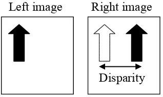
Figure 2-1 Features from left image are matched to features in the right image. The disparity between features found along the rows of the image
corresponds to the range of the feature. ... 7
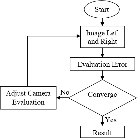
Figure 2-2 Flowchart of Tsai camera calibration model ... 8
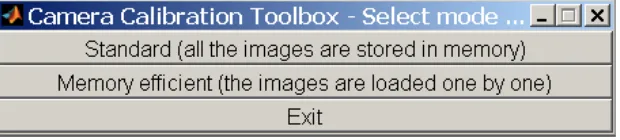
Figure 2-3 The Tsai camera calibration standard toolbox. ... 9
Figure 2-4 Main calibration toolbox ... 9
Figure 2-5 During the extrinsic calculation by the toolbox, the image taken is 4 X 4 matrix and from the figure the image is transform to digital three dimension calculation Xc, Yc and Zc plane by the original image Xw, Yw and Zw. ... 10
Figure 2-6 The intrinsic parameters are consisting of the image center, pixel size, distortion and focal length. ... 10
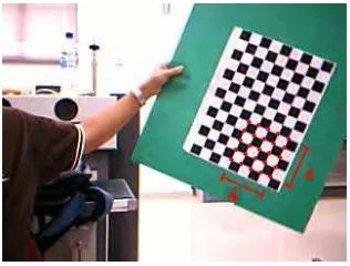
Figure 2-7 An example of calibration pattern 4x4 matrix on the chess board corners ... 10
Figure 2-8 Stereo camera toolbox ... 11
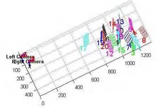
Figure 2-9 Extrinsic parameters from 3D view ... 11
Figure 2-10 Output images from left camera ... 12
Figure 2-11 Output images from right camera ... 12
Figure 2-12 Basic stereo vision with an obstacle point P ... 14
Figure 2-13 Epipolar plane in stereo vision ... 16
Figure 2-14 Image plane to get the matching point ... 19
Figure 3-1 The position of two cameras and their image plane ... 26
Figure 3-2 Flowchart of the software architecture in getting the output images ... 27
Figure 3-3 Overview of the AGV based obstacle detection for navigation ... 28
Figure 3-4 Image rectification process ... 29
Figure 3-5 Two images before go through the rectification process with the reference point PL and PR. ... 30
Figure 3-6 Zooming images of correspondence point PL and PR ... 30
Figure 3-7 Rectified image from the original image from Figure 4-5 ... 31
Figure 3-8 Original image before histogram equalization ... 32
Figure 3-9 New image after histogram equalization ... 33
Figure 3-10 Depth estimation procedures ... 33
Figure 3-11 The block matching algorithm, computing each point of the left image block for every position through the corresponding epipolar line in the right image. Figure 3-12 is the pseudo code for block matching algorithm. ... 35
Figure 3-12 Pseudo code for block matching algorithm ... 35
Figure 3-13 The disparity mapping image ... 36
Figure 3-14 Cropped disparity mapping image ... 37
Figure 3-15 Curve Fitting Tool ... 37
Figure 3-16 The AGV structure ... 39
Figure 3-17 System architecture of this project ... 40
Figure 3-18 Real representation of AGV ... 41
Figure 3-19 Flowchart of AGV movement phase... 42
Figure 4-1 Stereo vision of obstacles detection ... 43
Figure 4-2 Relation of disparity and distance ... 44
Figure 4-3 Relationship of pixel values and range ... 45
Figure 4-4 The AGV navigation in Mechatronic Lab with obstacles ... 46
Figure 4-5 Original stereo images at scene V1 ... 47
Figure 4-6 Disparity mapping from original image ... 47
Figure 4-7 Disparity mapping in digital value for un-rectified image ... 48
Figure 4-8 Rectify stereo images from V1 scene... 48
Figure 4-9 Area of AGV detection ... 49
Figure 4-10 Disparity mapping from V1 scene ... 49
Figure 4-11 Digital disparity mapping ... 50
Figure 4-12 Disparity mapping with cropped size ... 50
Figure 4-13 Pixel values from V1 scene ... 51
Figure 4-14 Distance mapping in meter from V1 scene ... 51
List of Tables
Table 2-1 Intrinsic parameters of left camera ... 13
Table 2-2 Intrinsic parameters of right camera: ... 13
Table 2-3 Extrinsic parameters (position of right camera) ... 13
Table 2-4 Extrinsic parameters (position of left camera) ... 13
Table 4-1 Disparity and range mapping... 45
Table 4-2 Pixel and range data from Matlab ... 52
Table 4-3 Pixel and range data from real measurement ... 52
List of Abbreviations
AGV Autonomous Guided Vehicle
PL Point Left
PR Point Right
USB Universal Serial Bus
NI-DAQ National Instrument Data Acquisition
FFT Fast Fourier Transform
SAD Sum of Absolute Difference
GHz Giga Hertz
GB Giga Byte
RAM Read Access Memory
Chapter 1 –
Introduction
1.1 Overview
A number of years have passed from the time when the first stereo vision systems were implemented in the industrial of robotic, but there are still no clear guidelines in terms of design and system architecture. Computers are improving in speed and memory capacity, camera prices are stable or even decreasing, potential is still growing, but, how good is stereo when compared to other type of sensors? What can, particularly, be sensed with stereo cameras? What problems are expected? Many questions remain unanswered, and therefore, research on this topic is welcomed. Stereo vision entered the arena of sensors in the eighties and today there are many automatic solutions which rely on it. Stereoscopic vision, by contrast, became popular only a decade ago with the release of compact binocular cameras. The principal advantage of stereo over usual monocular vision is the availability of the third dimension or range.
However, the advantages of stereo are still many and a practical command of stereo data is practicable with nowadays technology. Machine stereo vision is inspired from the human vision system. The origin of the word “stereo” is the Greek word “stereos” which means firm or solid, with stereo vision, the objects are seen solid in three dimensions with range (Rovira-Más, 2004). In stereo vision, the same seen is captured using two sensors from two different angles. The captured two images have a lot of similarities and smaller number of differences. In human sensitivity, the brain combines the captured to images together by matching the similarities and integrating the differences to get a three dimension model for the seen objects. In machine vision, the three dimension model for the captured objects is obtained finding the similarities between the stereo images and using projective geometry to process these matches. The difficulties of reconstruction using stereo is finding matching correspondences between the stereo pair.
Several applications of stereo vision have been developed during the last decade. The applications have also been put into practice on rovers to help out an autonomous navigation and safeguarding, typical applications where the availability of the distance camera-object results essential. In this project, the disparity mapping for navigation of stereo vision guided autonomous vehicle is one of the methods in applying the guided autonomous vehicle instead of using the active sensor. Basically a stereo vision is a passive sensor, meaning that it uses the radiation available from its environment. It is non-intrusive as it does not need to transmit anything for its readings. Differ from an active sensor sends out some form of energy into the atmosphere, which it then collects for its readings. For example, a laser sends out light that it then collects; and radar sends out its own form of electromagnetic energy. A passive sensor is ideal when one wants to not influence the environment or avoid detection.
An autonomous navigation requires a number of various capabilities, including the ability to execute uncomplicated goal-achieving actions, like reaching a given location; to react in real time to unexpected events, like the sudden appearance of an obstacle; to build, use and maintain a map of the environment; to determine the robot's position with respect to this map; to form plans that pursue specific goals or avoid undesired situations; and to adapt to changes in the environment (Jones, 2006). In a navigation of a stereo vision autonomous guided vehicle robot research, the goal is to build up a vehicle that can navigate at a certain speeds using stereo camera whether in outdoor or indoor environments such as fields or building. These vehicles require massive computational power and powerful algorithm in order to adapt their sensitivity and control capabilities to the certain speed of motion and in avoidance of obstacles.
1.2 Statement of Problem
In this project, the development of stereo vision from a pair of webcams to become a sensor for stereo vision is a big challenge. The horizontal configuration for stereo vision needs to be calibrated using a tool from software. The application is applied on autonomous guided vehicle. There are control and communication methods developed for autonomous guided vehicles. The problems such as coordination of places, motion planning and coordination of autonomous guided vehicles are generally approached with a central controller in mind or processor device. There is extensive research being carried out on autonomous mobile robots. Many solutions to the problems, including path planning and obstacle avoidance have been proposed and tested. Nevertheless, most of the research on autonomous guided vehicles was based on a single robot interacting with its environment. The problem of autonomous navigation of AGV involves certain complexities that are not usually encountered in other robotic research areas. For instance, the dynamic nature of the world, in indoor or outdoor environments, requires a real representation to be more consistent. Moreover, in order to achieve autonomous navigation, the decision making must be based on the continuous searching of images and mapping it thoroughly.
1.3 Thesis Aims and Objectives
The overall objective is to develop, optimize and test disparity mapping algorithm for navigation of stereo vision guided mobile robot using image processing software Matlab. The standard disparity mapping algorithm is to be applied. A number of disparity mapping techniques are available to be examined and tested for fast sampling rate requirement of mobile robot navigation. In addition the understanding of how the mobile robot interprets the information to navigate the site or testing the location with obstacles according to modified algorithm given by the processor/laptop. The algorithm is developed using the image processing software Matlab. First, the artificial stereo pairs are used as an input to the algorithm. Secondly, the images captured then transferred to be processed in image processing software Matlab. At the next stage, after that is
proved that the algorithm is capable to find the disparity images on both synthetic and a real world images, it has implemented on hardware.
1.4 Project Outline
The remainder of this project is organised into four chapters as follows:
Chapter 2 presents a literature review of this project. Firstly, the explanation of camera calibration using Tsai method and the results of intrinsic and extrinsic parameters. The process of camera calibration is an important issue in computer vision. A very careful calibration is needed to obtain highly precise measurements. The calibration procedure determines the projection parameters of the camera, as well as the transformation between the coordinate systems of the camera and the AGV. This chapter also tells the theoretical about stereo vision and its problems such as correspondence problem and obstacles avoidance. In this project the correspondence problem is solved by using correlation pixel method and is described in this chapter. Furthermore, this chapter also have a discussion about how to avoid an obstacle for AGV navigation.
Chapter 3 describes about the methodology of this project. The explanations are starting with capturing stereo images until the navigation of AGV. For the first part, the architecture of Matlab programming concludes the methodology of using the matching algorithm to find the best correspondence pixels between two images. Then the final output is a disparity mapping from the images.
In Chapter 4, tells about the result and discussion for this project. The result of AGV navigation in the Mechatronic Lab will determine the relationship between the disparity mapping and range in meter. This chapter also justify how are the AGV avoid the obstacles in front of it.
The conclusion and future work of this project is given in Chapter 5. The autonomous machine using a stereo vision system is related closely with the epipolar geometry, disparity, stereo image constrain and block matching algorithms. In this chapter also point up some extra ideas for the future work on this project.
Chapter 2 –
Background
2.1 Introduction
From the previous autonomous robotic technology, the famous type of sensor is using the active sensors such as LDR, laser, sonar and etc. Sensor based navigation systems that only rely on active sensors that provide one dimensional distance profiles have a great simplicity for collision and obstacle avoidance. Moreover, the active sensors cannot present the images or recording the environment that it’s covering during the navigation. A general adaptable control structure is also required. The mobile robot must make decisions on its navigation tactics, decide which information to use to modify its position, which path to follow around obstacles, when stopping is the safest alternative, and which direction to proceed when no path is given. In addition, sensors range information can be used for constructing maps of the environment for short term reactive planning and long-term environmental learning.
The AGV is mechanical devices capable of moving in an environment with a certain degree of independently. Autonomous navigation is associated with the availability of external sensors that capture information from the environment through visual images, or through distance or proximity measurements. Now, Autonomous navigation is equipped with a camera for two dimension image perception. Most of them have using their camera for grabbing a snap shot of their environment. The single camera solution can provide the depth image information, only while the robot or the observing object is moving. In contrast, the stereoscopic camera solution can provide the third dimension by grabbing simultaneously the left and right cameras, like as humans’ binocular vision. To realize the stereoscopic vision algorithms in this project, it requires generally a very fast processor for acquisition and computation of the huge amount of image information. Some research groups therefore have decided to use FPGAs in their embedded systems for image processing approaches, because of some advantages in the parallelism performance and the flexibilities.
2.2 Camera Calibration
Typically, in stereo vision system the two cameras are very important. It means, these cameras should have the same characteristic. The selections will depend on the same size of pixel and manufacturer. After that, the installation of these two stereo cameras on the AGV, they have to be adjusted to get the aligned pictures or images. The installation must be horizontally aligned with the range in between is about six centimetres (Fulton, 2004). That is, cameras are placed at the same elevation. The process of stereo vision is then usually defined as finding a match between features in left and right images as shown in Figure 2-1. In this project, the horizontal baseline is used where the cameras are placed side by side of each other. In this case, the stereo vision consists of finding match between left and right image. In reality, the cameras will not have absolutely aligned optical axes. So, the images taken with this pair of stereo vision cameras will also contain some distortions.
The main form of distortion in images is radial distortion where the images are compressed towards the edges (Tsai, 1986). This occurs most prominently in wide angle lenses. Another form of distortion is lens de-centering where the center of focus of the lens does not line up with the center of the image. This depends on the lens setting manually. If the output is clear and a sharpest image, then the part of processing image will produce the best pixel matching. The first step in the application of stereo vision is to change the poor images into an idealized stereo pair. Having idealized images makes the process of finding corresponding pixels in the two images easier. First the images are undistorted. Then they are rotated and scaled so that they fit the ideal geometrically. And then the process of rectifying the images will ensure the images captured by stereo cameras (Tsai, 1986; Tsai, 1987).
Construction of a full model from the stereo pair requires calibration of the camera system using software. From a stereo camera system (stereo rig) has accurately specified intrinsic and extrinsic parameters for both cameras. According to (Tsai, 1986; Tsai, 1987) the intrinsic camera parameters specify a pinhole camera model with radial distortion. The pinhole model is characterized by its focal length, image centre, pixel spacing in two dimensions and the radial distortion is
characterized by a single parameter. The extrinsic parameters describe the relative position and orientation of the two cameras. Intrinsic parameters for a given camera are constant, assuming the physical parameters of the optics do not change over time, and thus may be precalculated.
Figure 2-1 Features from left image are matched to features in the right image. The disparity between features found along the rows of the image corresponds to the range of the feature.
After stereo cameras installation, these cameras have to be calibrated. In order for stereo correlation techniques to work accurately and for the range results that they yield to be accurate and really represent the real world, the effects of the camera and lens distortion must be taken into consideration. The process of camera calibration is generally performed by first assuming a simplified model for both the camera and the distortion of resulting images and then statistically, fitting the distortion model to the observed distortion. Once the distortion has been modelled, it can be applied to the distorted image to correct it (Tsai, 1986).
The image processing software will use this result to get the accurate disparity values. Once a model of the camera and distortion have been chosen they are fit to the real camera and lens by comparing where points of accurately know real world coordinates appear in the image and where they would appear if there was no distortion. The error is minimized over as many points as is reasonable to fit distortion correction function to the distortion observed in the test scene (Tsai, 1986; Tsai, 1987). This distortion correction function, when applied to a raw image, reduces the distortion and what appears as a straight line in the real world appears as a straight line in the image.
Disparity Left image Right image
2.2.1 Method of Camera Calibration
Note that the purpose of camera calibration is trying to improve the transformations, based on measurements of coordinates, where one more often uses known transformation to map coordinates from one coordinate system to another. Tsai’s method for camera calibration recovers the interior orientation, the exterior orientation, the power series coefficients for distortion, and an image scale factor that best fit the measured image coordinates corresponding to known target point coordinates. This is done in stages, starting off with closed form least squares approximation of some parameters and ending with an iterative non-linear optimization of all parameters simultaneously using these estimates as starting values. Importantly, it is error in the image plane that is minimized. Details of the method are different for planar targets than for targets occupying some volume in space. Accurate planar targets are easier to make, but lead to some limitations in camera calibration (Tsai, 1986; Tsai, 1987). The flowchart Figure 2-2 below shows the steps of calibration using the matlab’s toolbox. The first step is to get a set of images in digital form and start to evaluate the error between the images of left and right. If the images are not converge each other then the system will adjust the value of the camera evaluation until they converge. The adjusted value or parameters will be used as a result for calibration process to be used in rectifying process (Zhang, 2000).
In this project a standard toolbox from matlab is used to calibrate the stereo camera using the Tsai method in Figure 2-3. It has two option, standard and memory efficient menu. Normally in camera calibration, the standard menu is the preference. In standard mode, all the images used for calibration are loaded into memory once and never read again from disk. This minimizes the overall number of disk access, and speeds up all image processing and image display functions. However, if the images are large, or there are a lot of them, then the out of memory error message may be encountered. If this is the case, the new memory efficient version of the toolbox may be used. In this mode, every image is loaded one by one and never stored permanently in memory.
Figure 2-3 The Tsai camera calibration standard toolbox.
The selection of the standard menu to make sure the time is cut down while the programming is running in Matlab. By selecting the standard mode by clicking on the top button of the window, the main calibration toolbox window appears on the screen and replacing the mode selection window from Figure 2-4.
Figure 2-4 Main calibration toolbox
To obtain both extrinsic parameters from Figure 2-5 (Sebastian Thrun, 2003) and intrinsic parameters from Figure 2-6 (Sebastian Thrun, 2003) of the stereo camera system the Tsai method uses a chess board as calibration pattern. The process of camera calibration can be divided into three steps.
Firstly the image acquisition for twenty images, then after that extraction of the chess board corners in each image with 4x4 matrix from Figure 2-7 and finally computing the intrinsic and external parameters using the submenu in Figure 2-4 above.
Figure 2-5 During the extrinsic calculation by the toolbox, the image taken is 4 X 4 matrix and from the figure the image is transform to digital three dimension calculation Xc, Yc and Zc plane by the original image Xw, Yw and Zw.
Figure 2-6 The intrinsic parameters are consisting of the image center, pixel size, distortion and focal length.
Figure 2-7 An example of calibration pattern 4x4 matrix on the chess board corners
Figure 2-8 Stereo camera toolbox
And then the display windows shows by Figure 2-7 is to illustrate the extrinsic and intrinsic parameters from the left images Figures 2-9 and right images Figure 2-10. This display window has utilities to save and load the result of calibrated stereo camera to be used by main program of stereo matching.
Figure 2-9 Extrinsic parameters from 3D view
Figure 2-9 shows the extrinsic parameters of the camera system and the position of the twenty chess boards in front of the cameras within the pictures seen in Figure 2-10 and Figure 2-11. The world coordinates of the chess board corners relative to each camera are known and the position of the left camera with respect to the right camera is calculated. The results of camera calibration are shown in Table 2-1, Table 2-2, Table 2-3 and Table 2-4. The result of each camera is displayed in pixel values. It still has plus minus with the error detected during calibration process. The Matlab created two files with different file names for left and right image in extension filename.mat. These files will be used by main stereo program.
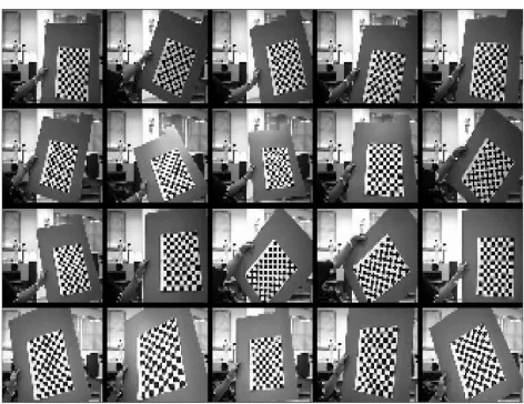
Figure 2-10 Output images from left camera
Figure 2-11 Output images from right camera
The extraction of the chess board corners needs to be done manually within the Matlab implementation of Tsai’s calibration method. After that the computing of the intrinsic and extrinsic parameters is done automatically. First every camera is calibrated separately before the global extrinsic parameters are calculated. The output images of left and right camera are positioned at same vertical positions but the horizontal coordination is totally different. If the images are out of frame during capturing activity, it must start back the procedures of calibration. As described earlier, the 4x4 matrix is selected on the chess board every image taken. So the matlab will used this selection as a reference frame to the calibration process for each twenty images left and right.
Table 2-1 Intrinsic parameters of left camera
Focal length [ 372.90575 373.58482 ] ± [ 5.14011 5.07494 ] Principal point [ 159.76547 91.23921 ] ± [ 5.46331 5.76730 ] Skew [ 0.00000 ] ± [ 0.00000 ]
Distortion [ 0.19492 -1.07074 -0.01118 -0.00091 0.00000 ]
Table 2-2 Intrinsic parameters of right camera:
Focal length [ 373.83866 373.83178 ] ± [ 4.82569 4.85865 ] Principal point [ 167.07304 139.96128 ] ± [ 5.64311 5.82166 ] Skew [ 0.00000 ] ± [ 0.00000 ]
Distortion [ 0.19645 -0.84041 -0.01428 0.00668 0.00000 ]
Table 2-3 Extrinsic parameters (position of right camera)
Rotation
vector [ -0.00757 0.16506 -0.00930 ] ± [ 0.01161 0.01458 0.00162 ] Translation
vector [ -47.82594 1.48281 3.10607 ] ± [ 0.77822 0.53278 4.14571 ]
Table 2-4 Extrinsic parameters (position of left camera)
Rotation
vector [ -0.00757 0.16506 -0.00930 ] ± [ 0.01161 0.01458 0.00162 ] Translation
vector [ -47.82594 1.48281 3.10607 ] ± [ 0.77822 0.53278 4.14571 ]