Multibody Dynamics Models of Railway Vehicle Using Adams/Rail
Azhar Ibrahim
1,a, Mohd Azman Abdullah
1,band Khisbullah Hudha
2,c 1Faculty of Mechanical Engineering,Universiti Teknikal Malaysia Melaka, Durian Tunggal, 76100 Melaka, Malaysia
2
Faculty of Engineering,Universiti Pertahanan Nasional Malaysia, Kem sungai Besi, 57000 Kuala Lumpur, Malaysia
a
[email protected], b [email protected], [email protected]
Keywords: Multibody dynamics, railway vehicle body roll angle, Adams/Rail
Abstract. This research is focusing on multibody dynamics modeling data and parameter comparison. The comfort and stability of railway vehicle suspension can be measured by using Ride Index Machine and other sensors. Complete model of EMU82 from KTMB is adapted to multibody software, ADAMS/Rail. With ADAMS/Rail, the behavior and characteristic of each suspension element can be determined. The accuracy of the simulation model is verified by comparing the result of body roll angle in Adams/Rail and the actual test. As for the experiment, certain test track will be chosen and simulated in ADAMS/Rail. The selection of track is based on the design and curvature characteristic. In experiment, data of roll angle and lateral acceleration are necessary. For that purpose selected sensors such as tri-axis accelerometer and gyro will be used. The running performance of the KTMB EMU82 suspension will be gathered from the simulation.
Introduction
With increased railway vehicle speeds, the vehicle’s dynamic performance is negatively affected. The suspension of the vehicle had to be modified in order to compensate the deteriorated dynamic behavior. In order to understand the railway suspension behavior, a multibody simulation model was developed. A model was studied considering the roll angle and lateral acceleration of railway vehicle body. Multibody dynamics software, Adams/Rail was used for the modeling of the KTMB EMU82 railway vehicle. This paper comprehensively focuses on railway vehicle modeling, test track modeling and experimental of the actual railway vehicle/test track. Moreover, the results can more accurately reflect the actual dynamic of the vehicle and they will be a basis for the analysis of new KTMB model and test track in future work.
Multibody Vehicle Modeling
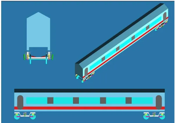
The KTM EMU82 railway vehicle was modeled by using ADAMS/Rail as analysis program. ADAMS/Rail is a specialized tool for modeling rail vehicles. It allows us to create virtual prototypes of rail vehicle, and analyze the virtual prototypes much like it would analyze the actual prototypes. Suspension system of the railway vehicle is divided into the primary suspension system and the secondary suspension system. These subsystems can be created by the user, using the creation mode templates, or predefined templates. A bogie modeling was applied to the primary suspension and the secondary suspension. The primary suspension consists of a coil spring and a vertical damper while the secondary suspension consists of an air spring, a vertical damper and a lateral damper. Both suspensions were applied in ADAMS/Rail according to the design value of all components in the suspensions. The basic data of mass and inertia of EMU82 is shown in Table 1 and Table 2. Various design parameters such as spring characteristic and damping coefficient were applied to the EMU82 simulation. The bogie model of the EMU82 railway vehicle is shown in Fig.1 and the complete model is shown in Fig.2. Based on these models, the dynamic characteristics of future railway vehicles are able to be analyzed and evaluated. In this study, a single car of the prototype was modeled and analyzed by ADAMS/Rail.
Table 1: Data of the weight condition
Mass (kg) Quantity Total
Car (Secondary sprung) 32,000 1 32000
Bogie(Primary sprung) 2615 2 5230
Wheelset(unsprung) 1503 4 6012
Table 2: Data of the inertia moment
Ixx (kgm2)
Iyy (kgm2)
Izz (kgm2) Car (Secondary sprung) 5680000 1970000 197000000
Bogie(Primary sprung) 1722 1476 3067
Wheelset(unsprung) 810 810 112
Fig. 1: EMU82 bogie model
Track Modeling
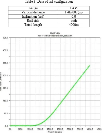
Track modeling plays an important role in this paper. An actual track length and curve were developed in the ADAMS/Rail. This model can be used to compare the results of the simulation model and the results of the actual test. The inputs of the parameters for both tests are taken from ADAMS/Rail multi-body simulations and KTMB track data. For the purpose of the experiment, the tracks were chosen based on the specified KTMB test area. The rail configuration of this track is shown in Table 3. In Fig.3 the rail profile of the test track is shown based on the actual test track curvature. The radius on track is based on the length of vertical and lateral coordinates of rail profile.
Table 3: Data of rail configuration
Fig.3: Rail profile plan (vertical coordinates (m) x lateral coordinates)
Simulations results
ADAMS/Rail will analyze every simulation separately. First, Preload and Linear Analysis will indicate if the system is stable or instable [2]. After that, the Stability Analysis will measure the critical velocity and the natural frequency. Finally, the analysis is completed with the Dynamic
Gauge 1.435
Vertical distance 1.4E-002(m)
Inclination (rad) 0.0
Rail side both
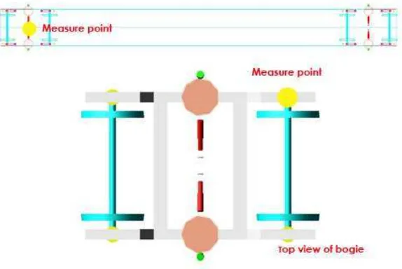
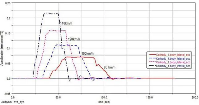
Analysis. These results consist of velocity, angular velocity, force, displacements, and irregularities data. The results of the simulations emphasis more on the lateral acceleration and the roll angle of the vehicle body. These data were gathered to determine the stability and comfort of the railway vehicle suspension. Acceleration measure points were appointed in the vehicle’s body and bogie, and after that the railway vehicle was driven on the irregular track lines. In Fig.4, the acceleration measure points were identified according to EN 14363[3]. Driving dynamic characteristics were analyzed in each point of the acceleration measurement. From these data, the detail observations of each railway vehicle’s suspensions, including primary and secondary suspension were gathered. The results based on the simulation test for body roll angle and body lateral acceleration are shown in Fig.5 and Fig.6. These data were obtained from different speeds of railway vehicle in between 80km/h to 140km/h. The speeds refer to UIC CODE 518 OR specific conditions for testing speed [4]. In Fig.5, the body roll angle increased during the 500m radius track and stabilized on the straight track. Body lateral acceleration also shows the same pattern during cornering.
Fig.4: Acceleration measurement points
Fig.6: Body lateral acceleration graph response
Conclusions and Future Works
A model of KTMB EMU 82 was developed using Adams/Rail. In dynamic analysis, result obtained for body roll angle is around 3.25deg which is stable for train vehicle. Also during 500m of track radius, the result for body lateral acceleration graph is acceptable. Lateral acceleration on the bogie frame is traditionally used to check the bogie stability. The limiting value for lateral acceleration is 8m/sec2 [5]. For future works, an experiment on actual test track will be implemented. Data from the actual test will be used for railway model validation.
Acknowledgement
The authors gratefully acknowledged the financial support from Universiti Teknikal Malaysia Melaka (UTeM) under short term grant : PJP/2011/FKM(26C)/S00981
References
[1] Bruni S, Goodall R, Mei T X and Tsunashima H: Control and Monitoring for Railway Vehicle Dynamics, Vehicle System Dynamics, Vol. 45, pp. 743-779, 2007
[2] Stribersky A, Steidl S, Müller H and Rath B: On Dynamic Analyses of Rail Vehicles With Electronically Controlled Suspensions, Vehicle System Dynamics, Vol. 25 (Suppl), pp. 614-628, 1996.
[3] “The European Standard EN 14363, Railway applications- Testing for the acceptance of running characteristic of railway vehicles”2005
[4] UIC CODE 518 OR, 3rd edition, General Conditions For Railway vehicle test.