Abstract—Ad hoc networks are becoming more important in
the modern complex environment. The ad hoc network can be used to instantly connect to the local or remote networks such as the Internet without the need of pre-existing infrastructure or centralized administration. The users of the network together will establish the infrastructure. The disadvantage of wireless communication is that it has limited range of radio transmission. Due to this, multiple network ‘hops’ are needed for one device to exchange data with another device across the network. In an ad hoc network, these devices will not only operate as a host but also as a router to forward the packets. There are varieties of routing protocols targeted for this environment that have been proposed and developed. However, most of them suffer from high overhead data traffic. The main purpose of this project is to implement the ad hoc network with the existing network protocol that had already been used in network environment which is the Address Resolution Protocol (ARP). ARP was designed to announce or find MAC addresses. The novelty of this study is that we have extended the usage of the ARP protocol to act as routing protocol in wireless ad hoc network. The ARP route provides two new operation types, ARP Forward Request and ARP Forward Reply to allow the multihop transmission using intermediate nodes to forward the request and reply. These two operation types only used the current operation codes which are ‘0x0001’ for request and ‘0x0002’ for reply. This work on the routing protocol creates a new operation code for the ARP forwarding scheme which is ‘0x000c’ for forwarding. We have successfully managed to create a multi hop transmission in an ad hoc network by using the current existing operation code for the ARP forwarding. The work scope focus only on proving that the method can be applied hence it is not necessarily to prove the effectiveness of this proposed method yet. Therefore, the outcome of the study shows that the data can be sent through multi hop transmission until it reaches the destination. The 802.11b test-bed has been configured and the ARP routing protocol has been implemented for multi hop transmission. The experiment in the open space provides the comparison of environment with obstacles and without obstacles. We manage to get more than 50% of packet receive at a place with no obstacles and more than 45% in a place with obstacles. The proof of method is shown by using several graphs namely in terms of time, packet loss and also throughput.
Index Terms—Address Resolution Protocol (ARP), Ad-hoc,
Hopping, 802.11 Wifi.
I. INTRODUCTION
Nowadays, the technology for wireless communication has made tremendous advantages where it allows a very high mobility, efficient working and almost extremely economical. Ad hoc is one of the communication technologies which provide the possibility for wireless devices to communicate directly with each other [1]. Ad hoc mode allows all wireless devices to operate within the range of each other to discover and communicate in peer-to-peer fashion without using central access points. Ad hoc network is a network that makes pre-existing infrastructure obsolete and it provides dynamic topology. The network has the ability of self-healing structure that makes the communication less vulnerable for failing links. This means that, even when the communicating devices are removed or added in the network, the information still can make its way through the network to its final destination.
Due to the limited transmission range of the wireless network interfaces, sometimes the data exchange from one node to another may not be successful across the network. Thus, multiple “hops” networks are needed to exchange data between the nodes across the network. In such a network, each of the nodes will not only operate as a host but also as a router where the forwarding packets from one node to another in the network may not be within direct wireless transmission range of each other. Each node that participates in an ad hoc routing protocol will discover ‘multi-hop’ path through the network to any other node. The idea of an ad hoc networking is sometimes also called infrastructure-less networking, since the node in the network will dynamically establish routing among themselves to form their own network ‘on the fly’.
The existence of ad hoc technology and the ‘multi-hop’ network are useful for the Vehicular Ad Hoc Network or VANET application. VANET provides communication among nearby vehicles and between vehicles and also nearby fixed equipments [2]. Each vehicle will be a node in the ad hoc network and it is equipped with VANET device. These nodes can receive and relay other message through the wireless network. In VANET, each vehicle takes on the role of sender, receiver and router to broadcast the information to the vehicular network or transportation agency. This information is used to ensure safety, and free-flow of the traffic. If two hosts are not within the radio range, all information or the data packets must pass through intermediate hosts which act as
Multi Hop Transmission in IEEE 802.11 Low Rate
Ad Hoc Network Using ARP-Route
Ida S.Md Isa1, Sharifah H.S.Ariffin2, N.Fisal2,N.M.AbdulLatiff2,N.Latif A.Shaari3, A.T.I Fayeez1
1Faculty of Electronic and Computer Engineering, Universiti Teknikal Malaysia Melaka (UTeM), Malaysia 2
Faculty of Electrical Engineering, Universiti Teknologi Malaysia (UTM), Malaysia 3
Faculty of Electrical Engineering, Universiti Teknikal Malaysia Melaka (UTeM), Malaysia [email protected]
routers and it performs the same job as routers. This is also called as multi hop where each node that participated in the network will discover multi hop paths through the network to any other nodes. In order to perform the multi hop between the nodes, a routing protocol is needed.
There are many different protocols that have been proposed to solve the multi hop routing problem in ad hoc networks. Each of this protocol is based on different assumptions and intuitions. Ad hoc routing is what underlies the establishment of the paths where VANET nodes can communicate with each other. The routing maintains the routes and makes it transparent to the user.
II. BACKGROUND STUDIES
Recently, there have been a lot of research activities in the area of routing protocol for wireless networks. Most of the works are based on simulations and very few works are based on the test-bed measurement or combination of the two.
In [6], the Optimized Link State Routing (OLSR) is evaluated through both the simulation and also a test bed. The author uses five wireless nodes equipped with IEEE 802.11b wireless network cards to simulate a mobile ad hoc network. Network simulator NS2 is used for the simulation and the Mobile Network Emulator (MNE) is used to emulate mobility of the test-bed with MAC address filtering. The results obtained from the simulation and the test bed measurement shows a good match.
In [4], Ad Hoc on Demand Vector (AODV) is used as a routing protocol to evaluate the effect of the hidden node problem in IEEE 802.11 wireless network. This study has been done in a test-bed and also in simulation work. A seven hops test-bed is established in a chain topology. All nodes are considered static and within the radio range of the previous and next hop nodes. The test-bed results are then compared with the network simulator 2 (NS2) simulation results. Interestingly, the simulation results and the test-bed results are very similar to each other. Besides, in [8] the performance of the AODV routing protocol for hybrid wireless mesh network is evaluated. The results obtained from the test bed network indicate that the AODV can perform effectively in hybrid wireless mesh network. It is able to handle a high volume of traffic with minimal latency. This paper also serves as a base line result for the exploration of larger and complex network topologies. This evaluation is done through the simulation and the real test bed and it shows a reasonable good correlation between both of them.
In [7], the Dynamic Source Routing (DSR) is used as a routing protocol over the IEEE 802.11b which serves as nodes in the test bed. This paper describes the design to facilitate experiments based on wireless ad hoc networks including radios mounted at fixed sites, on ground vehicles and in small Unmanned Aerial Vehicles (UAVs), laptop, PDA and special purpose ad hoc radios. The various components of the test bed and the issues faced during the experimentation are discussed. With the understanding of the performance of such network in the UAV scenario, it is necessary to understand the limits of multi-UAV operation [7]. Thus, the development of a wireless network test bed using the IEEE 802.11b radio equipment
mounted on small low cost UAVs is done [7]. From the test bed, the detail data on network throughput, delay, range and connectivity under different operating schemes are given. However, in [5], in order to find the high throughput paths on multi hop wireless network, the DSR and the Destination Sequence Distance Vector (DSDV) are implemented with the expected transmission count matrix (ETX). The modification to DSDV and DSR are made to allow the routing to be implemented in ETX. The ETX designed is used to minimize the expected total number of packet transmission and retransmission required to successfully deliver a packet to the destination. The minimum hop count metric chooses a path arbitrarily among the different paths of the same minimum length and ignore the possibility that a longer path might offer higher throughput. A test bed is done using the 802.11b with 29 nodes confirmed that the ETX improves the performance compared without using the ETX. For a long path, the throughput improvement is often a factor of two or more. So, the ETX could be very useful for a larger network and longer path.
In [9], the method of using the ARP for multi hop communication network is discussed. This paper presents how the ARP can be used in finding the route in an ad hoc network. This is also a new approach of using the existing routing protocol for the routing scheme. Based on the literature review, the idea of developing a new routing protocol using the existing network protocol is implemented in this project. A new operation code has been proposed which is ‘0x000c’ for forwarding scheme. Besides using less overhead, this protocol is also easy to be understand.
A. Address Resolution Protocol
The address resolution protocol (ARP) is a protocol that is used to map an Internet Protocol (IP) address to a physical machine address which is also recognized in the local network. In other words, ARP is also a method of converting the link layer address which is the medium access control (MAC) address from its network layer address like IP address. This protocol has been standardized by the Internet Engineering Task Force (IETF) in RFC 826 [3]. The ARP operates between the layer 2 and layer 3 in the OSI system model.
The ARP uses a simple format message which is a request message and respond message. Each message header has its own code where for request message the code is 1 and for reply message the code is 2. The payload in each packet consists of four addresses which are the hardware and protocol address of the sender and destination hosts. The ARP uses a cache to store mapped link layer address and network layer address to avoid network flooding. The ARP cache is used with an assumption that the MAC and IP address are rarely change and therefore the transmission of ARP message is considered as unnecessary. Besides, the ARP cache has a preconfigured timeout. This is to allow the ARP cache to remove the unused entries of route. This ARP cache is also used to allow the communicating devices to communicate faster without interference of ARP message and this utilized less network resources.
address to the MAC address, the typical size of an ARP messages is 28 bytes. Figure 1 shows the packet format of an ARP. The most significant field in the packet format is the operation code. Every message type uses a unique operation code.
32 BITS
8 8 8 8
HARDWARE TYPE PROTOCOL TYPE
HARDWARE ADDRESS
LENGTH
PROTOCOL ADDRESS
LENGTH
OPERATION
SENDER HARDWARE ADDRESS (OCTETS 0-3)
SENDER HARDWARE ADDRESS (OCTETS 4-5)
SENDER IP ADDRESS (OCTETS 0-1)
SENDER IP ADDRESS (OCTETS 2-3)
TARGET IP ADDRESS (OCTETS 0-1)
TARGET HARDWARE ADDRESS (OCTETS 2-5)
TARGET IP ADDRESS
Figure 1: The ARP packet format
B. Ad hoc routing using ARP
In this project, the implementation of multi-hop using ARP can be viewed as a self-configured routing protocol. This protocol does not need any pre-existing infrastructure. This routing operated as a reactive routing where the path will only be determined when there is data to be sent. Since this concept uses the ARP, the routing protocol operates on layer 2.5 which is between the data link layer and the network layer. As the routing operates at a lower level, the time for the process at the base station is decreased and the battery power is saved. Using the existing network traffic which employs ARP, the overhead traffic in network can be minimized. The ARP protocol is used to discover the routes. This will enable peer-to-peer communication between a source node and a destination node or a common wireless computer system. Ping application is used in this project where it will make use of the ARP protocol in order to find a route to the destination. When a route is established, then the Internet Control Message Protocol (ICMP) packet will be sent to the destination with the given path.
A route request is used in an ad hoc routing protocol to create routes to send data. There are two types of original ARP packets, which are ARP Request, and ARP Reply. The ARP Request is used to request for other node’s address. The ARP Reply is used by the recipient node to answer a request which is targeted to that node. Once the sender received the ARP Reply from the destination node, data can be sent to the destination node through the established routes. However, a new approach for multi-hop transmission is done in this project where there are two types of ARPs that have been proposed which are ARP Forward Request and ARP Forward Reply. Both of these ARPs are still using the same operation code where the ARP Forward Request used the same code as ARP Request which is ‘0x0001’ and the ARP Forward Reply
used the same code as ARP Reply which is ‘0x0002’. The IP packet is forwarded using the Internet router. The data is forwarded with a data link header that consists of the data link layer destination address.
C. The concept of multi hop transmission using ARP
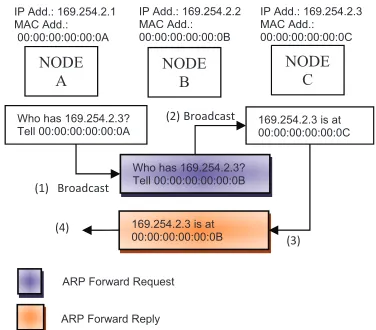
As mentioned before, there are two types of ARPs that have been proposed which are ARP Forward Request and ARP Forward Reply. The ARP Forward Request is used to allow the intermediate node or the neighboring nodes to retransmit the ARP Request over the network with some minor changes. The intermediate node needs to change the ARP Request packets where it will set itself as a sender and keep track the node that sends the ARP Request and next destination for the request. Besides, this packet is sent to create an ARP initiate route request. The ARP Forward Reply is to allow intermediate node to send and forward the ARP Reply received by the destination node to the sender node. This is also to ensure that the recipient is aware of both the destination and intermediate node. The data is forwarded according to the path created. Figure 2 shows three nodes with the multi-hop data through the destination.
In Figure 2, three nodes (Node A, Node B, Node C)are connected in a small network. The blue box illustrates the ARP Forward Request while the ARP Forward Reply is illustrated with the maroon box. Node A wants to communicate with Node C but cannot do it directly. However, Node B is positioned in such a way that it can relay messages or acts as an intermediate node between Node A and Node C. The ARP Forward Request will be sent by Node B to the destination node which is Node C and the ARP Forward Reply will be sent by Node B to the sender node which is Node A.
Figure 2: The ARP message to find a route path to destination
IP Add.: 169.254.2.2 MAC Add.: 00:00:00:00:00:0B
Who has 169.254.2.3? Tell 00:00:00:00:00:0A
Who has 169.254.2.3? Tell 00:00:00:00:00:0B
169.254.2.3 is at 00:00:00:00:00:0C
169.254.2.3 is at 00:00:00:00:00:0B
(1) Broadcast
(2) Broadcast
(4)
ARP Forward Request
ARP Forward Reply IP Add.: 169.254.2.1 MAC Add.: 00:00:00:00:00:0A
NODE A
NODE B
NODE C IP Add.: 169.254.2.3 MAC Add.: 00:00:00:00:00:0C
ARP Request ARP Reply
Ethernet Header Ethernet Header
Destination: FF:FF:FF:FF:FF:FF Destination: 00:00:00:00:00:0B Source: 00:00:00:00:00:0A Source: 00:00:00:00:00:0C
Type: ARP(0X806) Type: ARP (0x806)
Address Resolution Protocol Address Resolution Protocol
Hardware
Type: Ethernet (0x0001)
Hardware
Type: Ethernet (0x0001) Protocol
Code: Request (0x0001)
Operation
Code: Reply (0x0002) Sender HW
address: 00:00:00:00:00:0A
Sender HW
address: 00:00:00:00:00:0C Sender IP
address: 169.254.2.1
Sender IP
address: 169.254.2.3 Recipient HW
address: 00:00:00:00:00:00
Recipient HW
address: 00:00:00:00:00:0B Recipient IP
address: 169.254.2.3
Recipient IP
address: 169.254.2.2
ARP Forward Request ARP Forward Reply
Ethernet Header Ethernet Header
Destination: FF:FF:FF:FF:FF:FF Destination: 00:00:00:00:00:0A Source: 00:00:00:00:00:0B Source: 00:00:00:00:00:0B
Type: ARP(0X806) Type: ARP (0x806)
Address Resolution Protocol Address Resolution Protocol
Hardware
Type: Ethernet (0x0001)
Hardware
Type: Ethernet (0x0001) Protocol
Code: Request (0x0001)
Operation
Code: Reply (0x0002) Sender HW
address: 00:00:00:00:00:0B
Sender HW
address: 00:00:00:00:00:0B Sender IP
address: 169.254.2.2
Sender IP
address: 169.254.2.3 Recipient HW
address: 00:00:00:00:00:00
Recipient HW
address: 00:00:00:00:00:0A Recipient IP
address: 169.254.2.3
Recipient IP
address: 169.254.2.1
Figure 3: The ARP message packet
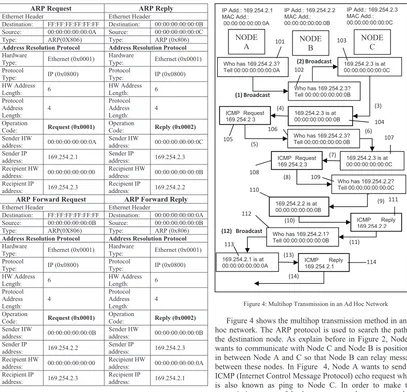
Figure 3 shows the contents of the ARP messages. As mentioned before, the forwarding scheme is proposed by only using the currently operation code with some minor modification. In order to make the sender starts to send ICMP packet data to the destination, the ARP Forwarding Reply packets sent by Node B is modified. Node B will act as the destination (Node C) where the “Sender IP address” is “169.254.2.3” instead of “169.254.2.2” but the operation code is still the same as current ARP Reply operation code (0x0002). Once the sender get reply from the destination, then only the ICMP packet data will be sent.
Figure 4: Multihop Transmission in an Ad Hoc Network
Figure 4 shows the multihop transmission method in an ad hoc network. The ARP protocol is used to search the path to the destination node. As explain before in Figure 2, Node A wants to communicate with Node C and Node B is positioned in between Node A and C so that Node B can relay message between these nodes. In Figure 4, Node A wants to send an ICMP (Internet Control Message Protocol) echo request which is also known as ping to Node C. In order to make this transmission successful, there are several messages which indicate the new message types communicated between the nodes. The flows of the scenario are illustrated as follows:
1. Node A starts its communication procedure by sending or broadcast an ARP Request asking for the location of the IP numbers it wants to communicate with. This is illustrated in box 101.
2. This ARP Request is received by Node B. Node B determines that the message request is not meant for itself but to another node. The message is forwarded or rebroadcast by Node B which is also known as ARP Forward Request. Here, the ARP Request packets is altered where, Node B will be set as sender. This message is illustrated in box 102.
3. The message is received by Node C and an ARP Reply is sent to Node B as illustrated in box 103.
IP Add.: 169.254.2.2 MAC Add.: 00:00:00:00:00:0B
Who has 169.254.2.3? Tell 00:00:00:00:00:0A
169.254.2.3 is at 00:00:00:00:00:0C
169.254.2.3 is at 00:00:00:00:00:0B
(1) Broadcast
(2) Broadcast
(4)
IP Add.: 169.254.2.1 MAC Add.: 00:00:00:00:00:0A
Who has 169.254.2.3? Tell 00:00:00:00:00:0B
ICMP Request 169.254.2.3
Who has 169.254.2.3? Tell 00:00:00:00:00:0B
169.254.2.3 is at 00:00:00:00:00:0C ICMP Request
169.254.2.3
Who has 169.254.2.2? Tell 00:00:00:00:00:0C
169.254.2.2 is at 00:00:00:00:00:0B
ICMP Reply 169.254.2.2 Who has 169.254.2.1?
Tell 00:00:00:00:00:0B
169.254.2.1 is at
00:00:00:00:00:0A ICMP Reply 169.254.2.1
(3) IP Add.: 169.254.2.3 MAC Add.: 00:00:00:00:00:0C
4. Once Node B receives the reply from Node C, then Node B will forward the reply message to Node A. Here, Node B will act as IP address of Node C but still using its MAC address. The forwarded message is also known as ARP Forward Reply as illustrated in box 104.
5. Node A then has the coordinates or path to reach Node C and then sends the ICMP request to Node C as illustrated in box 105.
6. Node B then relay the ICMP Request to Node C. Here, the ARP process is repeated where Node B know that the ICMP Request is meant for Node C and an ARP Request is broadcast to Node C as illustrated in box 106.
7. Node C then sends an ARP Reply to Node B as in box 107.
8. Node B sends or forwarded the ICMP Request from Node A to Node C as in box 108.
9. Node C received this ICMP Request and then wants to send an ICMP Reply. However, to send the reply, Node C needs to know the MAC address of Node B (since it received the ICMP Request of Node A from Node B). So, Node C then sends an ARP Request for Node B. This is illustrated in box 109.
10. Nodes B received the ARP Request from Node C and know that the request is meant for itself. Then Node B will send the ARP Reply to Node C as in box 110. 11. Node C received the reply from Node B and starts to send
the ICMP Reply to node B as illustrated in box 111. 12. When Node B received the ICMP Reply from Node C,
then Node B will automatically relay or forwarded the ICMP Reply to Node A by sending an ARP Request to Node A as illustrated in box112.
13. Node A received an ARP Request from Node B and replies an ARP reply to Node B as in box 113.
14. Node B then has the MAC address of Node A and start forwarded the ICMP Reply to Node A as in box 114 and the ICMP communication procedure is finalized.
The above process describes communication method involving ICMP request/reply. This method is using the standard message by using the current operation code field with some modification. The operation code used to define types of message is transmitted or received. In this project, the operation code used is still the standard request and reply, however, for the proposed forwarding scheme, some modification is made without adding new operation code and the routing using the ARP protocol is successfully done.
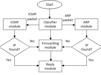
Figure 5 is the flow chart for the operation of an intermediate node, which consists of five processes: Classifier Module, ARP Module, ICMP Module, Forward Module and Reply Module. The Classifier Module is used to check the type of packets that enter the node either it is an ICMP Packet or ARP Packet. If the packet type is ICMP Packet, then it will invoke the ICMP Module while if the packet type is ARP Packet, and then this packet will invoke the ARP Module.
In ARP Module, there are six processes which are Check Packet Type, Check Target IP, Get Sender IP address, Save Sender IP Address, Get Sender MAC Address and Check Packet Status. Since there are two types of ARP Packet, ARP Reply and ARP Request, it differentiates the packet types by checking the packet type process. The Check Target IP
Process is to check whether the packet received is for the node itself or for other nodes. This is done by checking the IP address that is included in the received packet. The purpose of Get Sender IP Address is to store the sender IP and MAC address in the buffer.
Figure 5: The flow chart of the intermediate node
The Reply Module will be invoked when the packet is dedicated to that node and the address is saved. If the packet received is not for that node, then the target IP and the MAC address of the sender is saved and it will invoke the Forwarding Module. If the packet received is the ARP Reply Packet, then the IP checking is done by invoking Check Target IP process. The node will ignore the packet if the target IP of the received packet is not for the node. If the target IP of the received packet is for the node, then the Check Packet Status process is done. Here, the node will know if the packet received is a normal packet or from the forwarding request. If it is a normal packet, then the ARP Process is done and the ICMP Packet is invoked. Besides, if the packet received status is the forwarding packet, then it will get the sender IP and MAC address that has been stored in the buffer and invoke the Forward Module.
and llected in the e fty packets are st-bed deploym ge. If the replyi RP Reply Pack ard is shown in
istances are co
Figure 6: PIC Ex
re 7: Test-bed expe
de, then the n ket process is e Transmit ICM
xplorer 16 Board
eriment without ob ket is needed th
used and if it g the Explorer rocontroller. T n the experime ach location. T is measured. T et throughput
e of the locatio Figure 8 show Each of the tra collected time ed based on the ful message d
r at different nt strength. Thi
However, Fig es as the distan Th (
Test-bed experime
Time (RTT) of the nodes. T er. Node A ind y received at th
trip time, the livered over a ain network n e the average R
environment w is also cause th gure 9 also sho nce is longer.
ent with obstacle
for each tr The time is disp
dicates that the of the low rate which is the av
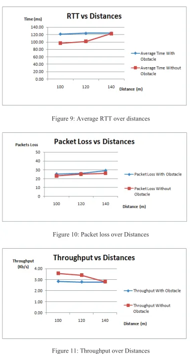
Figure 10 shows the packet loss during the packet transmission over the different distances of the nodes for two different environments. It shows that in both environments the results gives similar packet loss over the distance. The attenuation and the reflection of the signal could cause to signal lost. Thus the transmitted packet will also lose due to the lost signal. As it can be seen in Figure 10, the packet loss is higher as the distance is increased.
Figure 9: Average RTT over distances
Figure 10: Packet loss over Distances
Figure 11: Throughput over Distances
Figure 11 shows the throughput of the two different locations in kbps. Due to the different environments or locations of the experiments, the throughput varies significantly. From the graph obtained, it shows that at the place without obstacles, the throughput is much higher compared to that of the place with obstacles. The value of the throughput depends on the RTT that has been measured for each place. Since the average of the RTT at the place without obstacles is lower than the one with obstacles, the throughput for the place without obstacles is much higher. Besides, in a place with obstacles, the bit error rate is higher compared to that of the place without obstacles.
Besides the test bed experiment, the Wireshark software is also run to capture the packet being forwarded. In this experiment using the Wireshark, Node C which acts as a receiver is replaced with a laptop. The Wireshark capture the ARP packets and the ICMP packets that have been received at the receiver node. Here the results also prove that the data received at the receiver is the data from Node A which is relayed by Node B. In this experiment, Node A will send a data of “1111” while Node B contains data of “2222”. Figure 12 shows the results of the Wireshark capturing packet.
Figure 12:Wireshark capturing packet data
IV. CONCLUSION
This paper introduces the implementation of the ARP routing protocol for multi hop wireless network which operates in an ad hoc network. The route is determined by using the ARP protocol implemented in an ad hoc wifi device. This paper also presents the operation of an intermediate node in an ad hoc network to support multi hop transmission. The forwarding method for the ARP protocol is introduced by only using the existing operation code in the ARP standard protocol. From the results obtained, it shows that the 802.11b radio transceiver could operate well in an ad hoc network with ARP routing protocol This also proves that, this device with ARP could work not only in an open space area, but will also work in a place with obstacles. Moreover, based on the experiment it is shown that the performance of a network is affected by the surrounding environment and also the distance between the nodes.
The proposed method of multihop routing using ARP protocol can be enhanced by using more than 3 nodes. This proposed method can also be applied into a larger multihop network. Besides, this method can also be applied not only to a static network but also in a moving network such as VANET application.
ACKNOWLEDGMENT
REFERENCES
[1] J. Broch, D.A. Maltz, Yin-Chun H. and J. Jetcheva, “A Performance Comparison of Multi- Hop Wireless Ad Hoc Network Routing Protocol”, ACMMobicom Conference, October 1998.
[2] S. Kohli, B. Kaurand S. Bindra, “A Comparative Study of Routing Protocol in VANET” Proceeding of ISCET, 2010.
[3] RFC 826 ‘An Ethernet Address Resolution Protocolor Converting Network Protocol Addresses’, http://tools.ietf.org/html/rfc826. [4] P. C. Ng, S. C. Liew, “Throughput Analysis of IEEE802.11 Multi-hop
Ad hoc Networks”, IEEE/ACM Transaction, March 2005.
[5] D. S. J. De Couto, D. Aguayo, J. Bicket, R. Morris, “A High-Throughput Path Metric for Multi-Hop Wireless Routing”, Published by ACM 2003.
[6] F. Haq and T. Kunz, “Simulation vs. Emulation: Evaluating Mobile Ad Hoc Networking Routing Protocols”, In Proceedings of the international Workshop on Wireless Ad-hoc Networks (IWWAN’05), 2009. [7] S. S. Jadhay, T. X Brown, S. Doshi, D. Henkel, and Br. G.
Thekkekunnel, “Lessons Learned Constructing a Wireless Ad Hoc Network Test bed”, Proceeding of the First Workshop on Wireless Network Measurements WiNMee, 2005.
[8] P. Hu, A. A. Pirza and M.Portmann, “Experimental Evaluation of AODV in a Hybrid Wireless Mesh Network”, The 5th Workshop on the
Internet, Telecommunication and Signal Processing WITSP’06), 2006. [9] L. Axelsson, Ander Lundstorm and Magnus Wesbergh, “Method,