UNIVERSITI TEKNIKAL MALAYSIA MELAKA
DEPTH OF CUT ANALYSIS USING PLASMA CUTTER FOR
HYBRID MACHINE INNOVATION
This report submitted in accordance with requirement of the Universiti Teknikal Malaysia Melaka (UTeM) for the Bachelor Degree of Manufacturing Engineering
(Manufacturing Process) (Hons.)
by
WAN MOHD AZAHAR BIN WAN MOHD YUSOFF B051010224
881211035151
DEPTH OF CUT ANALYSIS USING PLASMA CUTTER
FOR HYBRID MACHINE INNOVATION
WAN MOHD AZAHAR BIN WAN MOHD YUSOFF
B051010224
UNIVERSITI TEKNIKAL MALAYSIA MELAKA
ABSTRAK
Pada zaman moden sekarang, terdapat perningkatan penyelidikan dalam pemesinan dan penerokaan dalam inovasi teknologi. Salah satu kejayaan penyelidikan adalah mesin hibrid iaitu di mana gabungan dua atau lebih proses dalam sebuah mesin. Peningkatan persaingan dalam industri untuk mencapai kejituan yang tinggi selain kepercayaan dalam permesinan, mesin konvensional menjadi nadi dalam pelbagai industri. Proses konvensional yang selalu diketengahkan adalah Pemotongan Secara Plasma Udara. Kadar kejituan produk akhir dan kebolehan untuk memotong pelbagai bahan yang keras dan dapat membentuk rekabentuk yang komplek untuk memenuhi permintaan pasaran. Berdasarkan kajian terdahulu dalam tesis ini telah menganalisis rangka kerja untuk memaksimumkan keputusan, kaedah separa two factorial telah digunakan untuk tujuan tersebut. Siri orthogonal yang sesuai telah diputuskan berdasarkan bilangan parameter dan terdapat peringkat yang melaksanakan bilangan ujian yang minimum. Bahan kerja
ABSTRACT
DEDICATION
ACKNOWLEDGEMENT
Alhamdulillah and grateful to ALLAH S.W.T for giving me the strength, patience and perseverance in completing the Final Year Project
I would like to express my deep sense of respect and gratitude toward my supervisor Dr Mohd Hadzley bin Abu Bakar, who not only guided the academic/final year project work but also stood as a teacher and philosopher in realizing the imagination in practical way, I want to thank him for introducing me for the field of Optimization and giving the opportunity to work under him. His optimism has provided an invaluable influence on my career and outlook for the future. I consider it my good fortune to have got an opportunity to work with such a wonderful person.
I am especially indebted to my mother for their love, sacrifices and support. They are my teachers after I came to this world and have set great example for me about how to live, study and work. Also would like to convey my biggest thanks to all the Faculty of Manufacturing Engineering, University of Technical Malaysia Melaka staff for their encouragement to supporting me throughout my project.
TABLE OF CONTENT
1.2 Process Description 2
1.3 Problem Statements 4
2.3.1 Milling Machining Operation 12
2.3.1.1 End Milling 12
2.4 Cutting Tools. 13
2.4.1 Carbides (uncoated tool) 13
2.4.2 Coated carbide (coated tool) 14
2.5.1 Cutting Speed 16
2.5.2 Feed Rate 16
2.6 Plasma Cutting 17
2.7 Principle Of Plasma Arc Cutting 18
2.8 Plasma Cutting Capability 22
2.9 System 23
2.10 The Process of Air Plasma Cutter 24
2.11 Air Plasma Cutter Parameter 25
2.11.1 Current Flow Rate 25
2.13 Surface Integrity 30
2.13.1 Surface Topography 32
2.13.1.1 Surface Roughness 33
2.13.2 Surface metallurgy 37
2.14 Design Of Experiments (DOE) 38
2.14.1 2-Level Factorial Design 40
2.15 Laser Machining 40
CHAPTER3: METHODOLOGY
3.2 Define The Objective Of The Experiment 41
3.3 Jig Design 42
3.4 Determine the Input Parameters at Low Level and High Level 44
3.5 Design of Experiment Matrix 44
3.6 Identify the Appropriate Response Variable 45
3.7 Preparation of the Experiment 45
3.7.1 Workpiece Preparation 45
3.7.2 Haz 2 Mini Vertical Machining Centre 46
3.8 Conclusion and Recommendation 47
3.9 Flow Chart of Study 48
CHAPTER4 : RESULT AND DISCUSSION
4.1 Finish Jig Part 49
4.2 Experiment Layout 53
4.3 The Effect of the parameter on Distance off cut 54
4.3.1 Cutting Current 54
4.3.2 Feed Rate 57
4.3.3 Air Pressure 59
4.4 Analysis Of Variance (ANOVA) 61
LIST OF TABLE
Table 2. 1 Element in AISI D 12 8
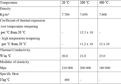
Table 2. 2 Properties table of AISI D2 8
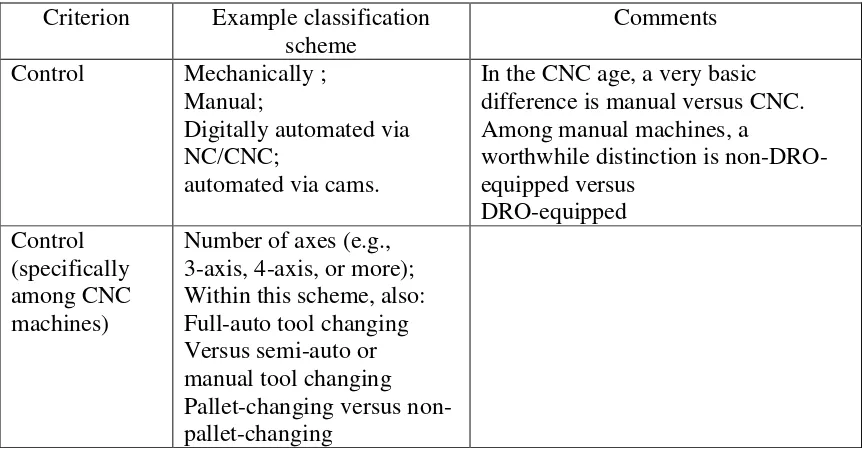
Table 2. 3 CNC machine criteria 9
Table 3. 1 Variable factor level 44
Table 3. 2 Design Matrix generated by Design Expert 7.0 software 44 Table 3. 3 Mechanical Properties of work material 46 Table 3. 4 Chemical composition and hardness of AISI D2 46
LIST OF FIGURE
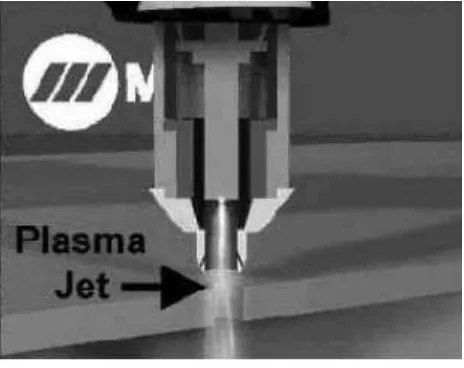
Figure 1.1 Plasma Jet 3
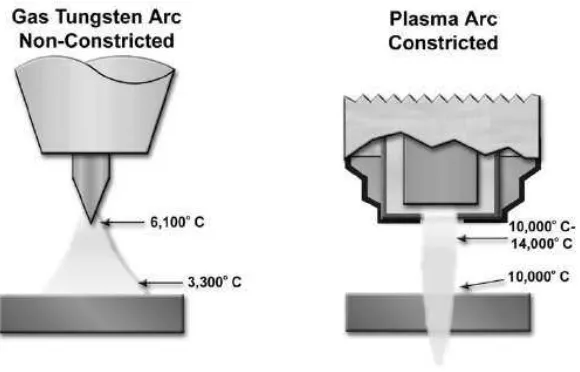
Figure 1.2 TIG and Plasma Arcs 4
Figure 2.1 CNC Milling Machine. 11
Figure 2.2 End milling 12
Figure 2.3 Usual carbide inserts with several shapes 15 Figure 2.4 The principle of the plasma cutting 19
Figure 2.5 Air Plasma 22
Figure 2.6 Air Plasma Setup 23
Figure 2.7 Air Plasma Cutter System 24
Figure 2.8 Torch Stand Off 27
Figure 2.9 Torch Breakdown 28
Figure 2.10 Electrode 29
Figure 2.11 Swirl Ring 29
Figure 2.12 Tip 30
Figure 2.13 The six clusters of important issues that explain the surface integrity of a
complete material 31
Figure 2.14 3D surface of machined workpice 32
Figure 2.15 Surface texture 33
Figure 2.16 Schematic section through a machined surface 37
Figure 3.1 Part 1 42
Figure 3.2 Part 2 42
Figure 3.3 Part 3 43
Figure 3.4 Part 4 43
Figure 3.6 Flow chart of the workpiece preparation 45 Figure 3.7 HAZ2 hybrid mini Machine Centre 46
Figure 3.8 Experiment Flowchart 47
Figure 4.1 Full assembly Jig 49
Figure 4.2 Part 1 50
Figure 4.3 Part 2 51
Figure 4.4 Part 3 51
Figure 4.5 Plasma Torch clamper 52
Figure 4.6 Complete Assembly jig attach to HAZ2 CNC Mini Milling Machine 52 Figure 4.7 Correlation between cutting speed and energy density 55 Figure 4.8 The relationship between current and DOC 55 Figure 4.9 The effect of parameter current on Distance of cut 56 Figure 4.10 The different between current 30 ampere and 20 ampere 56 Figure 4.11 Molten metal for low and high feed rate 57 Figure 4.12 The effect of feed rate on Distance Of Cut 57 Figure 4.13 Diagram for increasing and decreasing feed rate 58 Figure 4.14 The effect of parameter air pressure on Distance of cut 59 Figure 4.15 Different effect of changing Air pressure on Distance of cut 59
Figure 4.16 3D relationship graph 60
CHAPTER 1
INTRODUCTION
1.1 Introduction
Topic of this thesis writing is analysis of the surface integrity by using a plasma cutting for the hybrid machine technique. The focus of this project is keen to obtain an optimum condition (setting) and also to obtain maximum Distance Of Cut (DOC).
The result of the electrical arcs when air plasma is heating air to a high temperature to ionize its atoms (the result is due to an unequal number of electron to protons to an equal temperature an electrically is charged) and allowing it to conduct electricity. The light will be produced by a fluorescent lamp when you are reading by lights where you see plasma in action and containing of low pressure mercury within the shinning tube of the lamp. A across electrodes with a high voltage that is ionized at the ends of the tube conducts an electric current which result the plasma to radiate which in turn causes the phosphor coating on the inner surface of the tube to glow (Miller, 2013) .
an electrical metal such as stainless steel, aluminum; copper, brass etc will be cut by plasma cutter.
The cutting that is hotter and tighter than an oxy-acetylene flame is ensured by the plasma jet which gave kerfs width smaller with a cleaner cut. Compare with oxy-acetylene the plasma cutting mainly suitable for cutting a sheet metal and meanwhile a task the oxy-acetylene cutting torch is not mostly well-suited for since it leaves a lot of slag on the edges. Moreover the particularly tight focus of the plasma arc tends to reduce heat distortion in the cut parts.
For reaching high quality, in term of work piece dimensional accuracy, surface finish, high production rate, less wear on the cutting tools, economy of machining in terms of cost saving and increase of the product performance with reduced environmental impact are the challenges that mostly focused with. End milling is the ability to control the process for a better quality of the final product that is very commonly used and very high importance for machining process in machining industry.
Hardened steels are substantial in reducing machining costs and lead times compared to more traditional machine route which benefits in the manufacture of components (Koshy, 2002). AISI D tool steel group is extensively used in making molds and dies, but the machine ability of this group is very poor indeed.
1.2 Process Description
due to it is sufficient hot to melt the metal that has being cut and also fast to blow molten away from the cut (Sacks, 2005).
Figure 1.1- Plasma Jet
Figure 1.2 - TIG and Plasma Arcs
High temperature, constricted, high velocity jet of ionized gas exiting from the constricting orifice of the torch tip to melt a much localized area and remove the molten material from the metal being cut by the force of the plasma jet are where the APC process is used. This process is happened when the force of the arc pushes the molten metal through the work piece and severs with APC the material gave an extremely clean and accurate cuts are possible due to tightly focused heat energy that has a very little warping, even when cutting thin gauge sheet metal thickness.
1.3
Problem StatementsConventional materials exhibit in a very excellent technical properties. But however the constraints such as a high cost of both raw materials and processing limit their use. Alternatively the advanced machining such as Air Plasma Cutting is normally used. Material such as Stainless steel, Soft Steel and Aluminum can be used as the work piece in this type of cutting.
air tangentially into an electric arc formed between electrodes in a chamber and this is resulting vortex of hot gases emerges at very high speed through a hole in the negative electrode.
Compare to Oxy-Fuel torch or abrasive saws that are using low or no heat affected zone air plasma cuts ferrous and non-ferrous metal much faster. A clean cut with little or no dross means less time and money is required to finish the work piece. Parts are virtually weld-ready.
By using air plasma less preparation of work is required due it is hot enough to burn through most surface coatings such as paint and rust and still provides an excellent cutting results and minimal heat input and distortion of the metal as there is with jigsaws or cutting shears. Applications such as ventilation ductwork (HVAC), tanks or vessels, plasma cutting offers considerable advantage since there is no fixturing required are being used to handle difficult shape.
In order to obtain the best factors combination (Distance of Cut) an experiment and using full factorial methods of the processing is needed to prove feasibility and effectiveness.
1.4 Objectives
The objectives of this experiment are:
1. Design and fabricate a set of jig to guide the Plasma Air Cutter at the HAZ2 CNC Milling Machine.
2. To study about the influence of Plasma Air Cutting Parameters on Distance of Cut at Tool steel (AISI D2).
3. To design a series of experiment using the help of Design of Experiments (DOE) layout in order to study about Plasma Arc Cutting (PAC).
4. To study about the best combination of solution for maximizing the Distance Of Cut with full factorial method.
1.5 Scope of project
The scope of this project is to:
a) The design of Jig to guide the plasma cutter will perform using Solidwork 2012 software and no performance analysis will generate.
b) The fabricating of jigs design using CO2 Laser cutter machine for each part and use TiG welding machine for assembly section.
c) This project focuses on the optimization of cutting parameters of Plasma Air Cutting (PAC).
d) The material used as workpiece was Tool Steel of specification ASTM A681 D2 UNS T30402
e) Design of Experiments (DOE) layout will be used for testing and analyzing with Full Factorial Method.
CHAPTER 2
LITERATUREREVIEW
2.1 Introduction
This part describes the principle of milling process. Air plasma the parameters by referring the journal beside, cutting tools and workpiece. This chapter also include about basic introduction about solid work, laser cutting machine and several part about the jig design.
2.2 AISI D12 Carbon Steel
Table 2. 1 Element in AISI D 12 Standard Specification AISI D2, W-Nr 1.2379
Delivery condition Soft annealed to approx. 210 HB
Color code Yellow/ white
2.2.1 Application of AISI D2
AISI D2 is recommended for tool with high wear resistance and moderate toughness (shock-resistance) beside than that, it supply different finishes, which include hot-rolled, pre-machined, and fine machined condition. Refer table 2.2 for the properties of AISI D2.
Table 2. 2 Properties table of AISI D2
2.3 Milling Machine
Milling Machine is mechanism used to process, to produce the finish product and the chips from raw material. This Milling machines can be represented in two basic forms which are vertical and horizontal. Positioning of the cutting tool spindle is the basic form and meanwhile drill press is where work material static on the table and the cutting tool is moved vertically to machine the material otherwise milling machine which includes the movement of the work material against the spinning cutter .The movement of the cutting tool and work piece are accurately controlled to below than 0.025 mm, usually by means of precision instrument or analogous technology. Milling machines can be mechanically automated and may be manually operated, or digitally automated via computer numerical control (CNC). unnecessary number of processes, some complex, keyway cutting and such as slot, drilling, planning, rebating, die sinking, and routing can be performed by the Milling machine. Coolant is frequently pumped to the cutting site to lubricate and to cool the machining process. Techniques to categorize milling machines are dependent on which conditions are focuses: