Approximating the relationship among the degree of the reaction
forces and the nodes on footprint during a stance phase
A. Y. Bani Hashim
a,⇑, N. A. Abu Osman
b, W. A. B. Wan Abas
b, L. Abdul Latif
c aDepartment of Robotics and Automation, Faculty of Manufacturing Engineering, Universiti Teknikal Malaysia Melaka, Durian Tunggal, 76109 Melaka, Malaysia b
Department of Biomedical Engineering, Faculty of Engineering, University of Malaya, 50603 Kuala Lumpur, Malaysia c
Department of Rehabilitation Medicine, Faculty of Medicine, University of Malaya, 50603 Kuala Lumpur, Malaysia
a r t i c l e
i n f o
Article history: Received 20 March 2011
Received in revised form 4 November 2011 Accepted 13 November 2011
Available online xxxx
Keywords: Bipedal walking Edge
Graph Vertex
Vertical ground reaction force
a b s t r a c t
This study examined the foot biomechanics that are utilized when foot is in contact with the ground during a stance phase. The purpose of the study was to investigate the normal-ized ground reaction forces that impacted certain sections and points on the footprint, and to identify patterns in the degrees to which these forces occurred. Foot was modeled in such a manner that a vertex represented a bone and an edge represented a joint, and a graph that depicted the foot was created. Twelve nodes were marked on the footprint and these were linked together to create a gait path. By fusing the graph and the gait path and by manipulating the mathematical models, a profile for an ideal bipedal walking loco-motion was developed. A male subject performed bipedal walking through a force plate system in order to obtain the profile that reflected actual bipedal walking. The actual and the proposed profiles were compared and there were significant similarities between the two profiles, with both exhibiting an double-bump pattern. It is therefore viable that the approximation techniques proposed in this work may provide an alternative means over the application of a force plate system to generate a profile for bipedal walking. How-ever, the accuracy and reliability of the results yielded from this technique need further investigation.
Ó2012 Elsevier Inc. All rights reserved.
1. Introduction
This research involved an investigation of the foot biomechanics that are utilized when a foot is placed in contact with the ground during a stance phase. The purpose of the study was to investigate the normalized ground reaction forces that re-acted on certain sections and points on the footprint and to attempt to identify patterns in the degree to which these forces occurred. In order to do this, it was necessary to measure the ground reaction forces. Measuring these forces using a force plate is one method that is commonly applied. However, a force plate system produces output charts that provide no depic-tion of the reladepic-tionship between the ground reacdepic-tion forces and the bones and joints involved. The reacdepic-tion force patterns involved in human walking gait provide crucial information pertaining to the level of normality of the feet. If foot is abnor-mal, then the walking profile will follow a different pattern. Studying the reaction force patterns can be extremely beneficial because they can help to determine the level of foot normality[1], measure the gait biometrics[2], and allow an accurate reproduction of the foot in the form of prosthetic foot[3]. However, these benefits fall beyond the scope of the current study.
0307-904X/$ - see front matterÓ2012 Elsevier Inc. All rights reserved. doi:10.1016/j.apm.2011.11.089
⇑Corresponding author.
E-mail addresses:[email protected],[email protected](A. Y. Bani Hashim).
Applied Mathematical Modelling xxx (2012) xxx–xxx
Contents lists available atSciVerse ScienceDirect
Applied Mathematical Modelling
j o u r n a l h o m e p a g e : w w w . e l s e v i e r . c o m / l o c a t e / a p m
2. Background
The human foot has 27 bones[4]. The five digits called the phalanges are located at the extreme end of the foot, while the calcaneus, the largest bone, is located at the ankle. At the initial stage of a stance phase, sole-floor reaction force from the calcaneus dominates the distribution of reaction force, whereas the phalanges are effective towards the end. A stance phase has five sequences, which occur in the following order[5]:
(i) The initial contact (IC) with the ground, (ii) Heel strike (HS),
(iii) Mid stance (MS),
(iv) Forefoot contacts (FC), and end with (v) Push-off (PO).
The calcaneus is the first bone to bear the body weight upon contact with the ground. The body weight will then accu-mulate onto the navicular, the cuboid, and later onto the remaining bones. At the end of a stance phase, the last toe bears the body weight. The HS initiates the sequence in which specific bones will begin to have direct contact with the ground. The sequences of a stance phase apply to human locomotion; it is unknown if they also apply to other primates. However, a re-search has proven that the human foot has a lower total force in joints and muscles than that of an ape[6]. The kinematic pattern in human gait was proposed in[7].
Comprehensive gait analyses may be performed using a force plate system with special techniques, as suggested in[8]. The application of a force plate system to experiment with the walking patterns of healthy subjects that were wearing rocker shoes was reported in[9]. The function of gait analysis has been clinically evaluated[10], as too has the gait characteristics of persons with bilateral transtibial amputations[11]. However, the accuracy and reliability of the observational gait analysis data produced during this study was questionable[12,13]. As such, this work aims to approximate the reaction forces that act on the specific bones and joints by using an alternative measurement system to the force plate.
3. Methods
3.1. Proposition
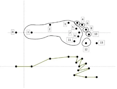
In completing one gait cycle, the foot undergoes a distinct sequence that follows a unique path; this is shown inFig. 1and is commonly referred to as the gait path. The path has fourteen nodes, 12 of which contain areas where the forces react. This has been extensively studied, especially in the early work of Elftman[14]. However, at present, Bani Hashim et al.[3]is the only study that proves the existence of the 12 nodes on the footprint. The path inFig. 1depicts nodeN0as the start point along the path as the foot descends. Similarly,N13is located along the path above the ground after the PO. The cycle begins at
N0and ends onN13. On the IC,N1, the calcaneus experiences the first force reaction impulse.
Proposition 1.Let the sequence of walking foot be a function of the nodes and the normalized GRF, so that Q(N,f).Every sequence has at least one node and a degree of reaction force except for sequence 0 and 13.
Proposition 2. Let the degree of the relationship(H)between the sequences, the nodes, and the reaction forces be represented by a
membership function(W).Then, the degree V depicts that a very large reaction force exists. Similarly, for the degrees: L, large; M,
medium; S, small; and A, absent. So that Eq.(1)definesHfor each foot of an ideal bipedal walking. Suppose that the relationships
are defined by natural numbers, wehaveWQN:(V?4,L?3,M?2,S?1,A?0):
Proposition 3. Suppose Eq.(2)defines the equivalent, the third-order trend line with vertical axis intercepts, and Eq.(3)is the sum of the estimate membership function, where the value defines the overall degree of the reaction force of that sequence. The
esti-mated membership function(W)becomes continuous but the Q and N remain discrete:
b
Definition 1. The double sum on the left hand side of Eq.(4)must equal to the double sum on the right hand side in order to verify the converted values of the membership function:
X13
Definition 2. Eq.(5)defines the estimated degree of the membership function (^h) after the function (W) has been converted into the trend lines:
Definition 3. Let the bones and the joints be represented by vertices (
m
) and edges (e) respectively. The graph that represents the foot is shown inFig. 2. If the gait path is embedded onto the graph, the reaction forces can be pinpointed to specificFig. 2.The gait path is embedded on the graph.
A. Y. Bani Hashim et al. / Applied Mathematical Modelling xxx (2012) xxx–xxx 3
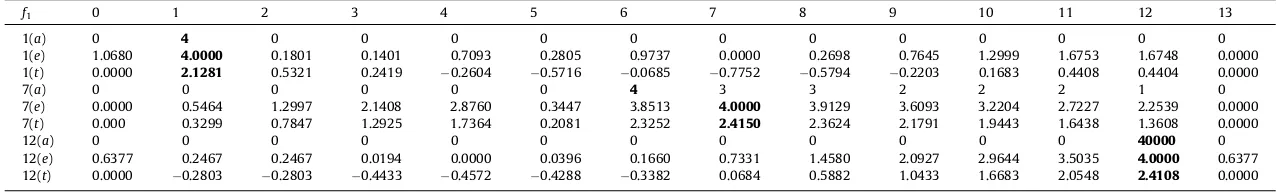
Table 1
List of bones and joints that experiencefk.
f1 0 1 2 3 4 5 6 7 8 9 10 11 12 13
1(a) 0 4 0 0 0 0 0 0 0 0 0 0 0 0
1(e) 1.0680 4.0000 0.1801 0.1401 0.7093 0.2805 0.9737 0.0000 0.2698 0.7645 1.2999 1.6753 1.6748 0.0000
1(t) 0.0000 2.1281 0.5321 0.2419 0.2604 0.5716 0.0685 0.7752 0.5794 0.2203 0.1683 0.4408 0.4404 0.0000
7(a) 0 0 0 0 0 0 4 3 3 2 2 2 1 0
7(e) 0.0000 0.5464 1.2997 2.1408 2.8760 0.3447 3.8513 4.0000 3.9129 3.6093 3.2204 2.7227 2.2539 0.0000
7(t) 0.000 0.3299 0.7847 1.2925 1.7364 0.2081 2.3252 2.4150 2.3624 2.1791 1.9443 1.6438 1.3608 0.0000
12(a) 0 0 0 0 0 0 0 0 0 0 0 0 40000 0
12(e) 0.6377 0.2467 0.2467 0.0194 0.0000 0.0396 0.1660 0.7331 1.4580 2.0927 2.9644 3.5035 4.0000 0.6377
12(t) 0.0000 0.2803 0.2803 0.4433 0.4572 0.4288 0.3382 0.0684 0.5882 1.0433 1.6683 2.0548 2.4108 0.0000
N:h;^h(bold number designate maximum value).
A.
Y.
Bani
Hashim
et
al.
/Applied
Mathematical
Modelling
xxx
(2012)
xxx–xxx
Please
cite
this
ar
ticle
in
press
as:
A.Y.
Bani
Hashi
m
et
al.,
Appro
ximating
the
relations
hip
among
the
degree
of
the
reaction
forces
and
the
nodes
on
footprin
t
during
a
stance
phase,
Appl.
Math.
Modell
.
(2012),
doi:
10.1016/j.a
pm.2011
vertices and joints, which is described inFig. 3.Table 1lists the bones and joints with their respectivefk!^h. Eq.(6)is the
Definition 4. Eq.(7)defines the sum of the graph walks:
X
There are 12 nodes on the footprint, each of which will have contact with the ground during a stance phase on at least one occasion. The estimated position of the nodes, as seen inFig. 1, suggests that bothN0andN13will never have contact with the ground during a stance phase. The respective sequences for these nodes are therefore, Q0 and Q13. As such, we have
Q0(N0,f0= 0) andQ13(N13,f13= 0).
During a stance phase, the foot experiences distinct reaction forces according to where in the sequence it is positioned. Upon IC, it is evident thatN1experiences the largest force, henceh?V= 4, whereas the remaining nodes haveh?A= 0.
This is shown in Row 1, the second row of Eq.(8). The remaining rows explain the pattern of the reaction force occurrences on different nodes. The first and last nodes do not have contact with ground. This is evident in the first and the last columns ofH: the largest weight while the rest of the nodes hold some of the weight.
Table 2lists the values forhandh^that were computed using Eqs.(1), (2), (5). The assumed sequence (Q1,a) is related to Eq.
(1). Similarly, the trend line sequence (Q1,t) to Eq.(2)and the estimated sequence (Q1,e) to Eq.(5). The values inTable 2 con-sist of three sets of data of the sequences that occurred during the IC (Q1), the MS (Q7), and the PO (Q12). It is evident that (Q1N1) and (Q12N12) have the largest value forhand^h. However, (Q7N7) has the largest value forh^, but the largesth seems to lie on the (Q7N6).
The plot ofFig. 2shows the relationship betweenP bWandN. It is apparent that there exist the local maximum atN1. The global maximum and minimum, however, are atN13andN2respectively. Eq.(7)was used to produce the profile for the de-gree of the normalized ground reaction force on an ideal bipedal walking in term of the graph walks (Fig. 4).
The experiment setup shown inFig. 5is one example of the application of a single force plate system to measure and record force values with respect to time. The subject walked towards the instrument and stepped on the force plate while walking. There are four charts inFig. 5, one for each time the subject repeated the experiment. The results of the bipedal walking profiles as obtained from a single force plate system were studied. The curves shown inFig. 5demonstrate a pattern
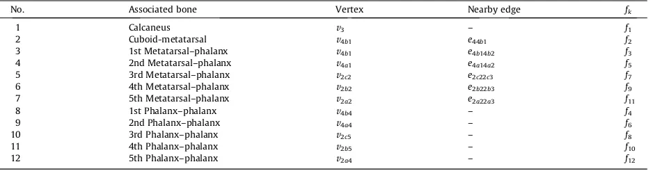
Table 2
The values ofhand^haccording to the sequences.
No. Associated bone Vertex Nearby edge fk
1 Calcaneus v3 – f1
A. Y. Bani Hashim et al. / Applied Mathematical Modelling xxx (2012) xxx–xxx 5
Fig. 5.The experiment setup used to study bipedal walking profiles using a single force plate system.
Fig. 3.The relationship betweenP bWandN.
Fig. 4.The profile of the degree of the normalized ground reaction forces on an ideal bipedal walking locomotion pattern. TheSw,3is the graph walk on MS.
that resembles the letter ‘M’. The two peaks indicate that foot was experiencing maximum body weight during IC, HS, and PO.
5. Conclusions
The fused graph and gait path were useful in producing a profile that measured the degree to which normalized ground reaction forces acted on specific nodes during the sequences utilized during an ideal bipedal walking locomotion. InFig. 2,N2 marked the midsection of the walking gait cycle – the MS. In addition,Fig. 4markedSw,3as the graph walk that represented the MS. A series of experiments were conducted using a single force plate system in order to measure the actual profiles uti-lized during bipedal walking. The effectiveness of this approach may be improved if a double force plate system were to be used. The chart provided inFig. 5exhibits a unique double-bump curve and this was also replicated in the chart inFig. 4. Therefore, the approximation techniques proposed in this work may provide a viable alternative to the force plate system as a method of generating a profile for bipedal walking.
Acknowledgements
This work is funded through the MOHE FRGS FRGS/2008/FKP(4)-F0069 and MOHE HIR.
References
[1] A.A. Zadpoor, A.A. Nikooyan, The relationship between lower-extremity stress fractures and the ground reaction force: a systematic review, Clin. Biomech. 26 (2011) 23–28.
[2] K. Nakajima, Y. Mizukami, K. Tanaka, T. Tamura, Footprint-based personal recognition, IEEE Trans. Biomed. Eng. 47 (2000) 1534–1537.
[3] A.Y. Bani Hashim, N.A. Abu Osman, W.A.B. Wan Abas, Prosthetic foot design: the significance of the normalized ground reaction force, in: N.A. Abu Osman, W.A.B. Wan Abas, A.K. Abdul Wahab, H.-N. Ting, (Eds.), 5th Kuala Lumpur International Conference on Biomedical Engineering, IFMBE Proceedings, Kuala Lumpur, Malaysia, 2011, pp. 765–768.
[4] A.Y. Bani Hashim, N.A. Abu Osman, W.A.B. Wan Abas, L. Abdul Latif, Evaluation of foot kinematic structure by the order of bones’ vertices and joints’ edges, Int. J. Model. Simul. 31 (2011) 11.
[5] A. Gefen, M. Megido-Ravid, Y. Itzchak, M. Arcan, Biomedical analysis of the three-dimensional foot structure during gait: a basic tool for clinical applications, J. Biomech. Eng. 122 (2000) 630–639.
[6] W.J. Wang, R.H. Crompton, Analysis of the human and ape foot during bipedal standing with implications for the evolution of the foot, J. Biomech. 37 (2004) 1831–1836.
[7] D.A. Winter, Kinematics and kinematics patterns in human gait, Hum. Mov. Sci. 3 (1984) 51–76. [8] J.K. Gronley, J. Perry, Gait analysis techniques, Phys. Ther. 64 (1984) 1837–1838.
[9] M.J. Peterson, J. Perry, J. Montgomery, Walking patterns of healthy subjects wearing rocker shoes, Phys. Ther. 65 (1985) 1483–1489. [10] R.K. Laughman, L.J. Askew, R.R. Bleimeyer, E.Y. Chao, Objective clinical evaluation of function gait analysis, Phys. Ther. 64 (1984).
[11] P.-F. Su, S.A. Gard, R.D. Lipschutz, T.A. Kuiken, Gait characteristics of person with bilateral transtibial amputations, J. Rehabil. Res. Dev. 44 (2007) 491– 502.
[12] J.L. McGinley, P.A. Goldie, K.M. Greenwood, S.J. Olney, Accuracy and reliability of observational gait analysis data: judgments of push-off in gait after stroke, Phys. Ther. 83 (2003) 146–160.
[13] D.E. Krebs, J.E. Edelstein, S. Fishman, Reliability of observational kinematic gait analysis, Phys. Ther. 65 (1985) 1027–1033. [14] H. Elftman, Dynamic structure of the human foot, Artif. Limbs 13 (1969) 49–58.
A. Y. Bani Hashim et al. / Applied Mathematical Modelling xxx (2012) xxx–xxx 7