i
DECLARATION
“I hereby declare that the work in this thesis is my own except for summaries and quotations which have been duly acknowledged.”
Signature : ……… Author : TIO KOK WEI
ii
DECLARATION
“I hereby declare that the work in this thesis is my own except for summaries and quotations which have been duly acknowledged.”
Signature : ……… Author : TIO KOK WEI
iii
ACKNOWLEDGEMENTS
Firstly, I would like to thank sincerely to my supervisor, Dr. Mohd Zulkefli Bin Selamat for spending his precious time in guiding me with his expertise and giving his moral support. The countless time that he spent in reflecting, encouraging, and advising patiently throughout the entire process and help me to finish my Final Year Project smoothly. Throughout this learning process, I have gained a lot of knowledge from him.
Secondly, I would like to thank PM Dr. Azma Putra and Dr. Rafidah Hasan as my panel who evaluated my work and provide me with useful opinions during presentation. Besides that, I would like to acknowledge and thank to the staff member especially the technicians in FASA B for providing any assistance requested. In addition, special thanks to the master students who help me a lot in understanding more details about my research.
iv
ABSTRACT
v
ABSTRAK
vi
TABLE OF CONTENT
CHAPTER TITLE PAGE
DECLARATION ii
ACKNOWLEDGEMENT iii
ABSTRACT iv
ABSTRAK v
CONTENT vi
LIST OF FIGURE ix
LIST OF TABLE xi
LIST OF ABBREVIATION AND SYMBOL xiii
CHAPTER 1 INTRODUCTION
1.1 FUEL CELL 1
1.2 PROBLEM STATEMENT 2
1.3 OBJECTIVES 3
1.4 SCOPE 3
CHAPTER 2 LITERATURE REVIEW
2.1 TYPES OF FUEL CELL 4
2.1.1 Polymer Electrolyte Membrane Fuel Cell 7
2.1.2 Components of PEMFC 8
2.1.3 Bipolar Plate 10
2.1.4 Development of Bipolar Plate 12
2.2 CONDUCTIVE POLYMER COMPOSITE 13
2.3 PERCOLATION THEORY 13
vii
2.4.1 Graphite Bipolar Plate 16
2.4.2 Metallic Bipolar Plate 17
2.4.3 Polymer Composite Bipolar Plate 18
2.5 MATERIALS 19
2.5.1 Graphite 19
2.5.2 Stannum 20
2.5.2.1 Physical properties and chemical properties for Stannum
21
2.5.3 Polypropylene 22
2.6 FABRICATION METHOD 24
2.6.1 Compression Molding 24
2.6.2 Injection Molding 25
2.7 TESTING METHOD 26
2.7.1 Electrical Conductivity of Bipolar Plates 26
2.7.2 Bulk Density 27
2.7.3 Shore Hardness 27
2.7.4 Flexure Strength 28
2.7.5 Microstructure Analysis 28
2.8 RESEARCH FOCUSES 29
CHAPTER 3 METHODOLOGY
3.1 EXPERIMENTAL OVERVIEW 30
3.2 MATERIALS SELECTION 32
3.3 FABRICATION METHOD 33
3.3.1 Characterization of Raw Material 33 3.3.2 The Composition of Raw Materials 35
3.3.3 Pre-Mixing 36
3.3.4 Preparation of Binder 37
3.3.5 Compression Molding 38
3.4 TESTING METHOD 40
3.4.1 Electrical Conductivity 40
3.4.2 Bulk Density 41
viii
3.4.4 Flexural Strength 43
3.4.5 Microstructure Analysis 44
CHAPTER 4 RESULT AND ANALYSIS
4.1 BASED OF THE PREVIOUS RESEARCH 45
4.2 DETERMINE THE FORMATION TEMPERATURE AND ELECTRICAL CONDUCTIVITY
47
4.2.1 The Formation Temperature and Various Sn Loading
48
4.3 FLEXURAL STRENGTH 48
4.4 BULK DENSITY 49
4.5 SHORE HARDNESS 49
4.6 MICROSTRUCTURE ANALYSIS 50
CHAPTER 5 DISCUSSION
5.1 DETERMINE THE FORMATION TEMPERATURE AND ELECTRICAL CONDUCTIVITY
52
5.1.1 The Formation Temperature and Various Sn Loading
54
5.2 FLEXURAL STRENGTH 55
5.3 BULK DENSITY 56
5.4 SHORE HARDNESS 58
5.5 COMPARING WITH PREVIOUS FINDINGS 59
CHAPTER 6 CONCLUSION AND RECOMMENDATION
6.1 CONCLUSION 61
6.2 RECOMMENDATION 62
REFERENCES 64
APPENDIX A 69
ix
LIST OF FIGURE
FIGURE TITLE PAGE
2.1 Basic Diagram of PEMFC 7
2.2 Major Components in the PEMFC 8
2.3 Relative cost and weight components from a PEMFC using Graphite Bipolar Plate
12
2.4 Schematics of percolation pathway 14
2.5 Percolation S-Curve 14
2.6 Structural Formula for Polypropylene 23
2.7 Schematic of electron transport in the cell 26
3.1 Fabrication Process of Gr/Sn/PP Composite Bipolar Plate in PEMFC
31
3.2 The sample of hybrid conductive fillers, Graphite(G/Gr) and Stannum(Sn) and the binder, Polypropylene(PP)
34
3.3 Ball Mill Machine 37
3.4 Preparation process of the binder (PP) 37
3.5 High Speed Hot Press Hydraulic Machine 38
3.6 Sample of Bipolar Plate 39
3.7 Mold used during Compression Molding Process 39
3.8 Jandel Multi Height Four-Point Probe 40
3.9 Electronic Densimeter 41
3.10 Type-D Analog Shore Hardness Tester 42
3.11 Proxxon Table Saw 43
3.12 Instron Universal Testing Machine (Model 5585) 43
x
4.1 Distribution of Sn, Gr and PP in the Composite 50
5.1 Graph of average value of Electrical Conductivity (S/cm) against Formation Temperature (oC)
53
5.2 Graph of average value of Electrical Conductivity (S/cm) against Weight Percentage of Sn (wt%)
54
5.3 Graph of average Maximum Flexural Strength (MPa) against Weight Percentage of Sn (wt%)
55
5.4 Graph of mean Bulk Density (g/cm3) against Weight Percentage of Sn (wt%)
57
5.5 Graph of average value of Shore Hardness against Weight Percentage of Sn (wt%)
xi
LIST OF TABLE
TABLE TITLE PAGE
2.1 Characteristics on Each Type of Fuel Cell 4
2.2 Materials and Function of Main Components in PEMFC 9
2.3 Functions of the Bipolar Plate in PEMFC 10
2.4 Requirement of US-DoE for Bipolar Plate 11
2.5 Physical Properties and Chemical Properties of Graphite 20 2.6 Physical Properties and Chemical Properties of Stannum 22 2.7 Physical Properties and Chemical Properties of
Polypropylene
23
3.1 Characteristics of the Materials 33
3.2 Composition for Gr/Sn/PP Composite based on the Weight Percentage (%)
35
3.3 Conditions and Parameters for Compression Process 38
4.1 Formation Parameters of the Bipolar Plate 45
4.2 Composition and Electrical Conductivity of Bipolar Plate 46 4.3 Average value of Electrical Conductivity for each specimen
at different Formation Temperature
47
4.4 Average value of Electrical Conductivity for each specimen at Formation Temperature of 170oC
48
4.5 Average value of the Maximum Flexural Strength for each specimen at Formation Temperature of 170oC
48
4.6 Mean Bulk Density for each specimen at Formation Temperature of 170oC
xii
4.7 Average value of Shore Hardness for each specimen at Formation Temperature of 170oC
49
4.8 Microstructure of Surface and Cross Section for each specimen at Formation Temperature of 170oC with 10X Magnification
51
xiii
LIST OF ABBREVIATION AND SYMBOL
PEMFC = Polymer Electron Membrane Fuel Cell AFC = Alkaline Fuel Cell
PAFC = Phosphoric Acid Fuel Cells MCFC = Molten Carbonate Fuel Cells SOFC = Solid Oxide Fuel Cells
MEA = Membrane Electrolyte Assembly GDL = Gas Diffusion Layer
CPCs = Conductive Polymer Composites HCC = Hybrid Conductive Composite PANi = Polyaniline
US-DoE = United State Department of Energy
ASTM = American Society for Testing and Materials
Gr = Graphite
Sn = Stannum
PP = Polypropylene
S/cm = Siemen per Centimeter
MPa = Mega Pascal
g/cm3 = Gram per Centimeter3
µA = Micron Ampere
1
CHAPTER 1
INTRODUCTION
1.1 FUEL CELL
Fuel cell is an electrochemical energy conversion device which can convert the chemical energy from hydrogen and oxygen into water, heat and in the process it will produces electricity. Hydrogen is commonly acts as fuel and sometimes hydrocarbons such as natural gas and alcohols like methanol are used. Fuel cells are different with batteries because a battery will eventually exhausted when the chemicals stored inside the cell has been used up. For the fuel cells, they can produce electricity as long as the inputs constant source of fuel and oxygen has been supply continuously. The electrolytic process will occurs and electricity will be generated. This process will never end up with the continuous supply of inputs.
2
combustion engine in vehicles and provide power in stationary and portable power applications because they are energy efficient, clean, and fuel flexible.
1.2 PROBLEM STATEMENT
3
1.3 OBJECTIVES
1. Study the effect of formation temperature on the properties of Gr/Sn/PP composite.
2. Determine the suitable process parameter for Gr/Sn/PP composite.
1.4 SCOPE
4
CHAPTER 2
LITERATURE REVIEW
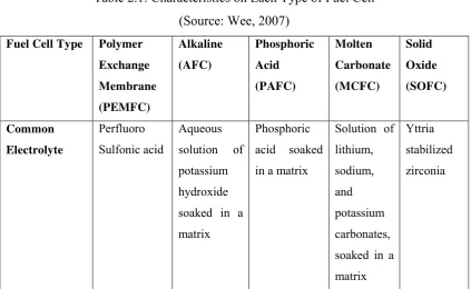
2.1 TYPES OF FUEL CELL
There are various types of fuel cells had been developed nowadays and they are classified according to the types of electrolyte used. There are classified as five types, which are polymer exchange membrane fuel cell (PEMFC), alkaline fuel cells (AFC), phosphoric acid fuel cells (PAFC), molten carbonate fuel cells (MCFC) and solid oxide fuel cells (SOFC). Table 2.1 shows the characteristics on each type of fuel cells.
Table 2.1: Characteristics on Each Type of Fuel Cell (Source: Wee, 2007)
Fuel Cell Type Polymer
Exchange Membrane (PEMFC) Alkaline (AFC) Phosphoric Acid (PAFC) Molten Carbonate (MCFC) Solid Oxide (SOFC) Common Electrolyte Perfluoro Sulfonic acid Aqueous solution of potassium hydroxide soaked in a matrix
Phosphoric acid soaked in a matrix
Solution of lithium, sodium, and potassium carbonates, soaked in a matrix
5
Fuel Cell Type Polymer
Exchange Membrane (PEMFC) Alkaline (AFC) Phosphoric Acid (PAFC) Molten Carbonate (MCFC) Solid Oxide (SOFC) Operating Temperature
50-100 oC
122-212oF
typically 80oC
90-100oC
194-212oF
150-200oC
302-392oF
600-700oC
1112-1292oF
700-1000oC
1202-1832oF
Typical Stack
Size
<1kW-100kW
10-100kW 400kW
100kW module 300kW- 3MW 300kW module 1kW-2MW
Efficiency 60%
transporta-tion 35% stationary
60% 40% 45-50% 60%
Applications Backup power, portable power, distributed generation, transporta-tionand speciality vehicles
6
Fuel Cell Type Polymer
Exchange Membrane (PEMFC) Alkaline (AFC) Phosphoric Acid (PAFC) Molten Carbonate (MCFC) Solid Oxide (SOFC) Advantages -Solid electrolyte reduces corrosion & electrolyte management problems -Low temperature -Quick startup -Cathode reaction faster in alkaline electrolyte, leads to high performance -Low cost components -Higher temperature enables CHP -Increased tolerance to fuel impurities -High efficiency -Fuel flexibility -Can use a variety of catalysts -Suitable for CHP -High efficiency -Fuel flexibility -Can use a variety of catalysts -Solid electrolyte -Suitable for CHP & CHHP
Disadvantages -Expensive
catalysts -Sensitive to fuel impurities -Low temperature waste heat -Sensitive to CO2 in fuel
7
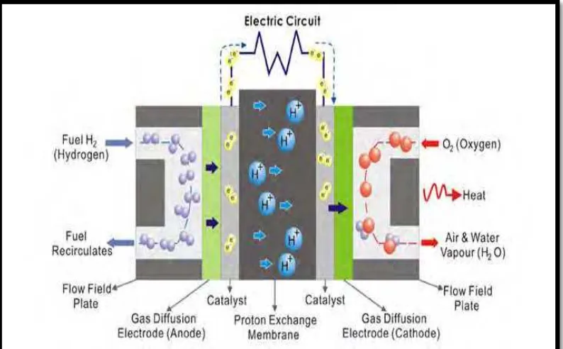
2.1.1 Polymer Electrolyte Membrane Fuel Cell
Polymer electrolyte membrane fuel cells (PEMFC) have emerged as the most common type of fuel cell under development today. It is also known as the proton exchange membrane fuel cells based on the key characteristics of the solid electrolyte membrane to transfer protons from the anode to the cathode. The solid electrolyte avoids problems caused by liquid electrolytes used in other systems, and the temperature range of <100oC enable rapid start-up under low temperature operation, with operation possible down to subfreezing temperatures. The lower temperature also allows a wider range of materials to be used and enables relatively easy stack design in terms of sealing issues and material selection (Cifrain et al. 2003). This type of fuel cell is the most feasible for use under transportation applications. The highly acidic membrane necessitates the use of highly reactive catalysts, with platinum being the only one in use today sufficiently active to achieve required performances (Wee, 2007). The fuel used can either be pure hydrogen or a hydrogen containing stream, typically produced from a reformed fuel, such as natural gas, methanol or other fuels like kerosene and propane. Figure 2.1 shows the basic diagram of PEMFC.
8
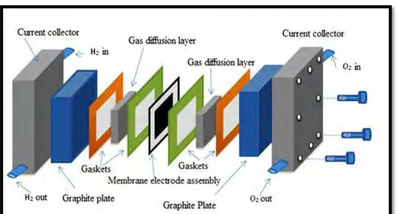
2.1.2 Components of PEMFC
Polymer fuel cells (PEMFC) are formed by the membrane electrolyte assembly (MEA), gaskets, gas diffusion layers, bipolar plates, current collectors and endplates. Figure 2.2 shows the majors components in the PEMFC and Table 2.2 shows the materials and function of main components in PEMFC. There are 4 main components of PEMFC:
1. Membrane Electrode Assembly (MEA) 2. Bipolar Plate
3. Current Collector 4. Endplate
9
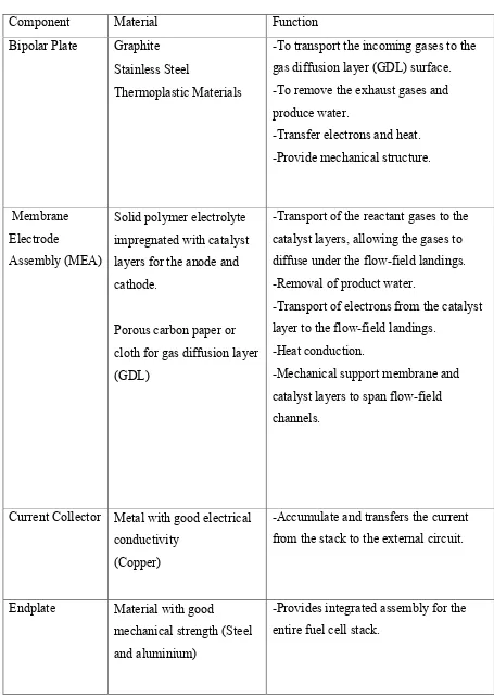
Table 2.2: Materials and Function of Main Components in PEMFC (Source: Wang, 2006)
Component Material Function
Bipolar Plate Graphite Stainless Steel
Thermoplastic Materials
-To transport the incoming gases to the gas diffusion layer (GDL) surface. -To remove the exhaust gases and produce water.
-Transfer electrons and heat. -Provide mechanical structure.
Membrane Electrode
Assembly (MEA)
Solid polymer electrolyte impregnated with catalyst layers for the anode and cathode.
Porous carbon paper or cloth for gas diffusion layer (GDL)
-Transport of the reactant gases to the catalyst layers, allowing the gases to diffuse under the flow-field landings. -Removal of product water.
-Transport of electrons from the catalyst layer to the flow-field landings.
-Heat conduction.
-Mechanical support membrane and catalyst layers to span flow-field channels.
Current Collector Metal with good electrical conductivity
(Copper)
-Accumulate and transfers the current from the stack to the external circuit.
Endplate Material with good
mechanical strength (Steel and aluminium)
10
2.1.3 Bipolar Plate
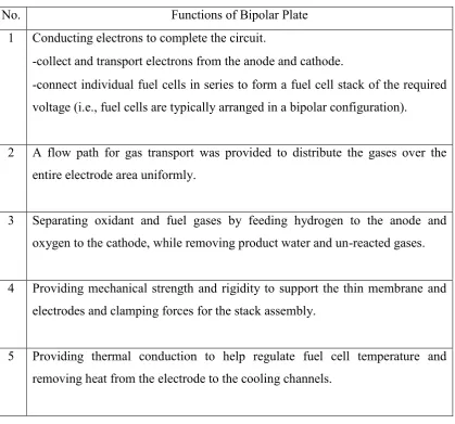
Bipolar plates (also known as flow-field plates) are as the most crucial component for the Polymer Electrolyte Membrane Fuel Cell (PEMFC) which is assembled on either side of the GDLs, the entire unit comprising the unit cell of the fuel cell stack. The plates are typically made out of carbon or graphite-polymer composite materials or metals. The bipolar plates act an important role due to its multi-functional in the fuel cell stack. According to Wang (2006), the functions of the bipolar plate in PEMFC are shown in Table 2.3.
Table 2.3: Functions of the Bipolar Plate in PEMFC (Source: Wang, 2006)
No. Functions of Bipolar Plate
1 Conducting electrons to complete the circuit.
-collect and transport electrons from the anode and cathode.
-connect individual fuel cells in series to form a fuel cell stack of the required voltage (i.e., fuel cells are typically arranged in a bipolar configuration).
2 A flow path for gas transport was provided to distribute the gases over the entire electrode area uniformly.
3 Separating oxidant and fuel gases by feeding hydrogen to the anode and oxygen to the cathode, while removing product water and un-reacted gases.
4 Providing mechanical strength and rigidity to support the thin membrane and electrodes and clamping forces for the stack assembly.
11
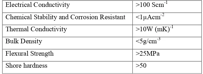
According to the United State Department of Energy (US-DoE), there are some basic requirements that need to be achieved by a standard bipolar plate due to its multiple responsibilities and the challenging environment in which the fuel cell operates (Wee, 2007). Table 2.4 shows the requirement of US-DoE for bipolar plate.
Table 2.4: Requirement of US-DoE for Bipolar Plate
Electrical Conductivity >100 Scm-1
Chemical Stability and Corrosion Resistant <1µAcm-2
Thermal Conductivity >10W (mK)-1
Bulk Density <5g/cm-3
Flexural Strength >25MPa
Shore hardness >50