DEVELOPMENT ON UWB BANDPASS FILTER USING
DEFECTED GROUND STRUCTURE
MUHAMAD AKMAL BIN TALIB
This Report Is Submitted In Partial Fulfillment of
Requirement for the Bachelor of Electronic Engineering
(Telecommunication Engineering)
Faculty of Electronic and Computer Engineering
Universiti Teknikal Malaysia Malacca
ii
UNIVERSTI TEKNIKAL MALAYSIA MELAKA
FAKULTI KEJURUTERAAN ELEKTRONIK DAN KEJURUTERAAN KOMPUTER
BORANG PENGESAHAN STATUS LAPORAN
PROJEK SARJANA MUDA II
Tajuk Projek : DEVELOPMENT ON UWB BANDPASS FILTER USING DEFECTED GROUND STRUCTURE Sesi
Pengajian : 1 4 / 1 5
Saya MUHAMAD AKMAL BIN TALIB
mengaku membenarkan Laporan Projek Sarjana Muda ini disimpan di Perpustakaan dengan syarat-syarat kegunaan seperti berikut:
1. Laporan adalah hakmilik Universiti Teknikal Malaysia Melaka.
2. Perpustakaan dibenarkan membuat salinan untuk tujuan pengajian sahaja.
3. Perpustakaan dibenarkan membuat salinan laporan ini sebagai bahan pertukaran antara institusi pengajian tinggi.
4. Sila tandakan ( √ ) :
SULIT* *(Mengandungi maklumat yang berdarjah keselamatan atau kepentingan Malaysia seperti yang termaktub di dalam AKTA RAHSIA RASMI 1972)
TERHAD** **(Mengandungi maklumat terhad yang telah ditentukan oleh organisasi/badan di mana penyelidikan dijalankan)
iii
“I hereby declare that this thesis entitled, Development on UWB Bandpass Filter Using Defected Ground Structures is a result of my own research idea
concept for works that have been cited clearly in the references.”
iv
“I hereby declare that I have read this report and in my opinion this report is sufficient in term of scope and quality for the award of Bachelor of Electronic
Engineering (Telecommunication Engineering) with honors.”
v
DEDICATION
„
In the Name of Allah, the most Beneficent, the most Merciful”
Special Dedication to parents:
Talib Bin Ahmad and Che Li Rohana Binti Madzhar
To my siblings
Nooryusma Laily Binti Talib and Noor Amira Binti Talib
To my beloved friend
vi
ACKNOWLEGMENT
First and foremost, I would like to thank my advisors Dr Mohd Azlishah Bin Othman and everyone who help me to complete this thesis. They shared their knowledge, their ideas, and numerous tips all of which culminated in the completion of this thesis. I would like to extend my sincere thanks to all of them for development, fabrication, and the measurements of the filter. I also like to thank members of the Department of Telecommunication, Faculty of Electronic and Computer Engineering (FKEKK), UTeM both past and present, for their invaluable support, assistance, mentorship, and feedback which I kept me on track of my research. Finally, an honorable mention goes to my parents and my friends for their understandings and supports on me in completing this thesis. Special thanks to them, to my family and to my friends. I am grateful to everyone who was on my side during my master thesis.
vii
ABSTRACT
viii
ABSTRAK
Dalam tesis ini, ultra-jalur lebar (UWB) penapis gelombang mikro dan cabaran reka bentuk dikaji dan, yang mikrostrip UWB reka bentuk prototaip penapis
ix
INDEX
CHAPTER TITTLE PAGE
STATUS OF CONFIRMATION II
DECLARATION III
x
2.1.1 Butterworth filter 6 2.1.2 Chebyshev filter 6
2.5 DEFECTED GROUND STRUCTURE 16 2.5.1 Advantages of DGS 18
4 RESULT AND DISCUSSION
4.1 ADS CIRCUIT SYNTHESIS 34
4.2 DEFECTED GROUND STRUCTURE 39 4.2.1 Dumbbell shape 40
xi
4.2.4 Arrow and dumbbell 43
4.2.5 Gap ring 44
4.2.6 Dimensions of the shape 45
4.3 FABRICATION & MEASUREMENTS 46
4.3.1 Fabricate step 46
4.4 MEASUREMENT 47
4.5 DEBUGGING AND FINAL FILTER MEASUREMENT 48
4.6 FURTHER DEVELOPMENT 49 5 CONCLUSION 5.1 CONCLUSION 50
xii
LIST OF TABLES
NO
TITLE
PAGE
xiii
LIST OF FIGURES
NO
TITLE PAGE
1.0 Basic Wireless Communication 2
2.0 Lowpass Graph 8 2.9 Measured and Simulated of Fabricated Filter 24
3.0 Flowchart 26
3.1 Circuit of Lowpass Filter 27 3.2 Simulation of Low Pass Filter 27 3.3 Circuit of Bandpass Filter 32 3.4 Simulation of Bandpass Filter 32 4.0 Initial Ads Optimized Circuit Schematic 35
xiv
LIST OF ABBREVIATIONS
LPF - Lowpass Filter HPF - Highpass Filter BSF - Bandstop Filter BPF - Bandpass Filter
ADS - Advanced Design System UWB - Ultra-Wide Band
IL - Insertion Loss RL - Return Loss
xii
CHAPTER 1
INTRODUCTION
1.1Project Introduction
Since the authorization of the unlicensed use of ultra-wideband (UWB) frequency band from 3.1–10.6 GHz for commercial application by Federal
Communications Commission (FCC) in 2002, the UWB technology has become one of the most promising technologies for short-range high-rate indoor wireless
2
selectivity filtering characteristics and relatively small size that uses defected ground structures (DGS) to suppress the spurious passband is proposed in this thesis.
Ultra-wideband (UWB) microwave filters and design challenges are studied and, a microstrip UWB filter prototype design is presented. The UWB bandpass filter operating in the 3.6 GHz to 10.6 GHz frequency band is targeted to comply with the FCC spectral mask for UWB systems. The prototype filter is composed of quarter wavelength spaced shunt stub transmission lines. The circuit is first simulated and optimized by using ADS simulation software tool. The fabricated microstrip UWB bandpass filter is then measured using a vector network analyzer and results are presented. The prototype built can be used in UWB communications or localization systems.
Figure 1.0: Basic wireless communication
1.2 Project Summary
3
1.3 Problem Statement
Ultra wideband (UWB) signals operate from 3.1GHz to 10.6GHz has been released by the Federal Communications Commission (FCC). However, there are some existing wireless communication system partially overlap with UWB system. Multiple-mode resonators (MMR) were implemented in the design of UWB BPFs and resulting in a wide pass-band covering the whole band of 3.1-10.6GHz. However, the out of band performance is not good enough due to higher order harmonics which arises just after the first pass band. UWB BPF with single or multiple notched bands are required in order to avoid interferences from undesired signal.
1.4 Objectives
4
1.5 Scope of Project
The main scope of this project is to design a bandpass filter. We need to design a filter in the range of 3-10 GHz.
5
CHAPTER 2
LITERATURE REVIEW
2.1 Filter
In signal processing, filter is device that functional to remove undesired signal and to accept only a signal that we want. There is different type of filter and bring own advantages and disadvantages. Some of the example is Butterworth, Chebyshev, Bessel and other. Electronic filter can be passive or active, analogue or digital, high pass, low pass, band stop or all pass. Passive filter can be the
combination of resistor, inductor and capacitor. Filters may be specified by family and band form. A filter's family is specified by the approximating polynomial used and each leads to certain characteristics of the transfer function of the filter.
6
2.1.1 Butterworth Filter
Advantages:
- Maximally flat magnitude response in the pass-band. - Good all-around performance.
- Pulse response better than Chebyshev. - Rate of attenuation better than Bessel.
Disadvantages:
- Some overshoot and ringing in step response.
This filter has the flattest possible passband magnitude response. Attenuation is -3dB at the design cutoff frequency. Attenuation beyond the cutoff frequency is a moderately steep -20dB/decade/pole. The pulse response of the Butterworth filter has moderate overshoot and ringing.
2.1.2 Chebyshev Filter
Advantage:
- Better rate of attenuation beyond the pass-band than Butterworth.
Disadvantage:
- Ripple in pass-band.
-Considerably more ringing in step response than Butterworth.
7
can be achieved by allowing more pass-band ripple. The Chebyshev has more ringing in its pulse response than the Butterworth - especially for high-ripple designs.
2.1.3 Bessel Filter
Advantage:
- Best step response-very little overshoot or ringing.
Disadvantage:
- Slower initial rate of attenuation beyond the pass-band than Butterworth.
8
2.2 Types of Filter
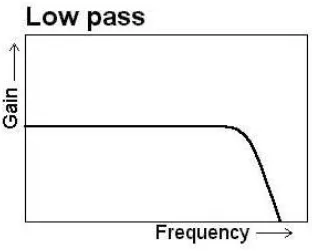
2.2.1 Lowpass Filter
The most basic filter is low pass filter. It rolls off all frequencies above its cut-off frequency with a particular slope. A low-pass filter is filters that go through signals with a frequency lower than a certain cutoff frequency and decrease signals with frequencies higher than the cutoff frequency. The filter design will affect the amount of attenuation for each frequency.
9
2.2.2 Highpass Filter
High-pass filter is an electronic filter that elapse signals with a frequency higher than a particular cut-off frequency and weakened signals with frequencies below the cutoff frequency. The amount of attenuation for each frequency depends on the filter design.
10
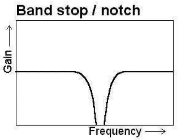
2.2.3 Bandstop Filter
Band stop filter will cut a few ranges of frequencies. Relative notch filter actually filters resonance. Band-reject filter is the complement of the band-pass filter. Thoughts high signal losses between the WC2 WC1, hence the name of the band-stop and band-reject. In this case, the denied frequency band located between these two pass-bands.
Band-stop filter features two pass-band; passband lesser beginning from zero to f pass1, temporarily passband of the start of SS2 in fi f munity.