DOI: 10.12928/TELKOMNIKA.v12i2.1948 273
Overview on Strategies and Approaches for FPGA
Programming
Tole Sutikno*1, Nik Rumzi Nik Idris2, Aiman Zakwan Jidin
Department of Electrical Engineering, Faculty of Industrial Technology, Universitas Ahmad Dahlan, Yogyakarta, Indonesia
Department of Energy Conversion, Faculty of Electrical Engineering, Universiti Teknologi Malaysia, Johor, Malaysia
Department Electronics & Computer Engineering Technology, Faculty of Engineering Technology, Universiti Teknikal Malaysia Melaka, Melaka, Malaysia
*Corresponding author, e-mail: [email protected], [email protected], [email protected]
Abstract
This paper presents an overview of strategies and approaches for FPGA programming. At first, design entry methods are briefly introduced. Then, the concepts of FPGA programming in some perspective viewpoints, such as: execution perspective, modelling perspective, programming style perspective, construction methodology perspective and synthesis perspective will be explained. Finally, the principle of VHDL programming use synchronization-evolution-action approach is introduced.
Keywords: VHDL programming, programming style perspective, synthesis, synchronization-evolution-action approach
1. Introduction
A field programmable gate array (FPGA) can be considered as a proper solution for boosting performance of controllers and for decreasing the gap between the analog and digital world [1-3]. FPGA can significantly accelerate the processing time of an algorithm [4, 5]. When addressed to fast ADC, the extremely fast computation capability of FPGA allows real-time computation of complex control algorithms in a few microseconds [2].
Today, FPGA vendors provide a fairly complete set of tools which allow high quality design process starting from the hardware description using VHDL. Generally, the design tools cover hardware design and verification tools (VHDL editor, synthesizer, place/route and physical implementation tools) [1, 6]. Some the examples are Quartus from Altera, Integrated Software Environment (ISE) from Xilinx [7] and Libero from Actel [8]. However, the understanding about perspectives of FPGA programming is needed to use the tools for realizing a digital design.
2. Design Entry Methods
Designing by hand on paper using techniques such as Boolean expressions, circuit schematics, Karnaugh maps, Quine-McCluskey (Tabular) minimization, and state transition diagrams were used in the past to design digital circuits. Currently, the design process migrated to the computer using electronic design automation (EDA) tools [9-11].
For entering a design into an EDA tool, a suitable design entry method is required. Typically, the design entry methods are following [12-14]:
- Circuit schematics, present a graphical view of the design using logic gate symbols and
interconnect wiring.
- Boolean expressions can be entered as a text-based description in combinational logic
designs.
- HDL design entry, allows a description of the digital logic circuit or system operation to be
entered in text form using a suitable language.
- State transition diagrams, present a graphical view of state machine that identifies the
design states and the transitions between states.
3. Concepts of VHDL Programming
VHDL is a hardware description language. However, the term “hardware” in this context is used in a wide variety of context, which covers the complete range of applications from complete systems such as personal computer to the small logical, and can be used for modelling digital hardware in a general way. VHDL is suitable for the design phases from system level to gate level. The existence of “IEEE Standard VHDL Language Reference Manual” has increased the use of VHDL and has enabled the creation and development of high-performance computer-aided-design (CAD) tool [15-18].
3.1. An Execution Perspective
The distinguishing of VHDL from other languages is in the way how assignments can be executed. Two basic types of statements are known as [19-21]:
a. Sequential statements
As in software programming languages, these statement types are executed one after another. So, the order of the assignment must be considered when use these types.
b. Concurrent statements
The types are active continuously where the order of the statements is not relevant. So the types are especially suited to model the parallelism of hardware.
3.2. A Modelling Perspective
Three important features of the modelling techniques are abstraction, modularity and hierarchy [22-25].
a. Abstraction
VHDL is rich in language constructions which can be used to describe different abstraction levels. Abstraction levels are a way of hiding details of a particular set of functionality. It allows for the description of different parts of a digital system with different amounts of detail. Thus, hierarchical and modular approaches which are defined at different levels of abstraction for taking advantages of the VHDL can be use in digital circuit design [22-25].
There are three different abstraction levels for hardware description languages have been defined to deal with the huge size of detailed information describing electronic devices. Each of level is characterized by a set of primitive component and by the size of information processed at that level [10, 22, 23].
- Behavioural level
The behavioural level is a simple way to describe the behaviour of a circuit. The level consists of the functional/algorithm description of the circuit. Usually, such descriptions are only simulatable, but not synthesizable.
- Register transfer level (RTL)
The RTL deals with words of bits using combinational and sequential devices such as word gates, multiplexers, decoders, arithmetic operators, registers, etc. Two different types of processes exist in RTL descriptions are the pure combinational process and the clocked process. All clocked processes infer flip-flops and can be described in terms of state machine. In depth of the state machine will explain in sections V and VI.
- Gate level
The logic level is well defined by switching theory based on Boolean or multi-valued algebra. It involves all of the logic gates processing Boolean of multiple-value bit-information. The logic networks must be optimized.
The complexity of designed ICs favoured the development of new design methodologies based on abstraction. Three strategies may be distinguished in design methodologies [26-29]:
- Top-Down, proceeds hierarchically from an abstract level to a more detailed one by
- Bottom-Up, achieves the design of more complex systems by assembling less complex
ones.
- Meet-in-the-middle, decomposes a system into subsystems until the parts of the resulting
decomposition can be designed using a library of component and standard cells. This last approach is the most frequently used.
b. Modularity
For very large models, it is useful to split the whole code into many files that can be compiled separately. A big functional block can be split into smaller units and grouped closely related parts in self-contained sub-blocks, so-called modules. A complex system can be divided into manageable sub-systems by using this technique. From a functional point of view, the modules are easier to develop and make sense. This can be conducted by identification and extraction of some re-useable and independent modules [1, 22, 24].
c. Hierarchy
Hierarchy is useful for splitting an initial, complex problem into simpler sub-problems that can be worked out separately to achieve a solution to the initial problem. Using hierarchies to handle complexities does not mean that the design becomes less complex (sometimes it becomes more complex instead), but it become easier to understand for designer. By using hierarchy method, building a design out of modules is possible. Each level of a hierarchical description may contain one or more modules that can even have different degrees of abstraction. The sub-modules of these models are present in the next lower hierarchical level [23-25].
Modularity and hierarchy help to simply and organize a design project.
3.3. A Programming Style Perspective
VHDL offers three styles of description: the behavioural, dataflow, and structural styles. In contrast to other languages, the VHDL model may include any combination of the three abovementioned styles [7, 8, 12, 19, 30].
a. Behavioural style
A behavioural description models the system as to how the outputs act with the inputs. The behavioural style permits the designer to quickly test concept, where the designer can specify the high-level function of the design without taking much care how it will be done structurally. This description defines the functionalities of a device with a sequential algorithm with no reference to any structural implementation. For example, an adder will be modelled with an addition operation. The synthesized from behavioural descriptions will often end up using a lot of more resources than actually necessary, even after optimization. b. Dataflow style
Dataflow describes how the system’s signals flow from the inputs to the outputs. At the dataflow or the RTL style, the system is represented by a concurrent set of equations involving user-defined functions, and arithmetic and logic operators operating on signals of arbitrary complex types. These equations express the flow of information through RTL functional modules implied by the functions and operators. A direct hardware implementation can be derived by mapping signals into wires and dataflow operators in RTL modules. For example, an adder will be constructed by mapping signals into wires and dataflow of the predefined languages operators XOR, AND, and NOT.
c. Structural style
In a structural style, the description lists the parts of the system and their interconnections. Structural descriptions model the system as components or gates. Actually, the functionalities of the components are not part of the description. The components are viewed as black boxes with regard to their interface. The resulting system is equivalent to an interconnected set of sockets. For example, an adder could be described as the interconnection of two half-adders and an OR gate. In this case the half-adder and the gate are viewed as black boxes.
3.4. A Construction Methodology Perspective
Design of integrated circuit is a mapping process of functional description of a problem in order to satisfy a set of performance criteria. A construction methodology perspective may concentrate on any level of abstraction defined within this process: Recent literature on VHDL programming perspectives describe a number of distinct methodologies. All of these methodologies can be grouped into three mainstreams that differ in design philosophy [26-29]: a. Top-down approach (behavioural)
The design process is started from high-level, behavioural descriptions of blocks that will realize certain functions. A good example for the top-down approach is logic synthesis methodology. Standard cell libraries based-VHDL description of a digital circuit has become a commonly used technique for automatic synthesis of such circuits. This approach is addressed to avoid the complexities of physical design and thus, speeds up the process. Yet, the weakness of this approach cannot solve a number of issues such as careful speed optimization and area minimization.
b. Bottom-up approach (physical)
The low-level elementary building blocks of the circuit are designed and combined to realize the desired function. A good example of the bottom-up design strategy is full-custom and mask-level design of elementary building blocks. This approach quickly becomes very difficult to manage the overall design complexity in larger FPGA designs.
c. Meet-in-the-middle approach
The design of complex systems should employ a combination of top-down and bottom-up approaches which is called the "meet-in-the-middle" approach, for most efficient results.
3.5. A Synthesis Perspective
Synthesis is the translation process from a description of a hardware device at higher abstraction level into an optimized implementation on a lower level abstraction. This process may be done by human or a computer assisted program. There are two common categories of the synthesis process [10, 20, 26, 31-35]:
a. Behaviour to structure
The gap between the high-level behavioural specification of a digital circuit and its structure are bridged high-level synthesis. The high-level synthesis as opposed to logic synthesis which optimizes only combinational logic, deals with memory elements, the interconnection structure such as buses and multiplexers, and the sequential aspects of a design. The behavioural specification aims at describing only the functionality of a circuit, or what the circuit must do. On the other hand, circuit structure gives strong hints about the circuit's implementation or how it is built. The structure is described by a netlist, a list of components and their interconnections.
b. Structure to physical layout
Transformation from structure to physical layout representation is called physical design. Physical design Physical design includes two major parts: (i) the first part is the refinement process between the structural and physical views which derives a layout for a netlist; and (ii) The second part involves the analysis and tuning of a circuit's electrical characteristics. The main tasks in physical design include floor planning, placement and routing and circuit extraction.
The synthesis process can also be viewed in three different levels [10, 20, 26, 31-35]: a. Behaviour synthesis
Behavioural synthesis allows design at higher levels of abstraction by automating the translation and optimization of a behavioural description, or high-level model, into an RTL implementation which fits in with existing design flows. This method can be selectively applied to portions of a design. It will derive the greatest benefit from the using a higher level of abstraction. This behavioural design flow increases design productivity, reduces errors, and speeds verification.
b. Logic synthesis
Logic synthesis involves both combinational and sequential logic design.
optimized truth table or Boolean expression into gates of a particular technology. c. Physical synthesis
Physical synthesis is the last stage in a synthesis design flow and is where the individual gates are placed and routed on the specific FPGA platform.
4. Using Arithmetic Operations and Types
In VHDL, the declaration of the constants, signals, variables, functions and parameters can be conducted with a type that defines and restricts their characteristics. When objects are assigned to a type, they are restricted to the values and operations for that type [18, 36, 37].
Altera recommends using the following types [37]:
a. STD_LOGIC and STD_LOGIC_VECTOR types. These types are defined in IEEE Std 1164-1993 [38]. A copy of the std_logic_1164 package, which includes these types, is provided in the ieee library in the \quartus\libraries\vhdl\ieee directory.
b. BIT and BIT_VECTOR types. These types are defined in IEEE Std 1076-1987 [15]. A copy of the standard package, which includes these types, is provided in the std library in the \quartus\libraries\vhdl\std directory.
c. SIGNED and UNSIGNED types. These types are provided in the std_logic_arith, numeric_std, and numeric_bit packages in the ieee library in the \quartus\vhdl\ieee directory.
5. State Machine
Boolean form can be used to specify all programmable logic designs. However using non-Boolean models are easier to conceptualize and implement some designs. The one such model is state machine model. A state machine represents a system as a set of states, the transitions between them, along with the associated inputs and outputs. So, it is a particular conceptualization of a particular sequential circuit which can be used for many other things beyond logic design and computer architecture [27, 33, 35, 39, 40].
A finite state machine (FSM) or simply a state machine is a model of behaviour composed of a finite number of states, transitions between those states, and actions. It is like a "flow graph" where we can see how the logic runs when certain conditions are met [27, 33-35, 39, 40].
6. Synchronization-evolution-action approach in state machine
A state machine is acting as a sequential circuit. The use of state machines is an effective means of implementing control functions. The current state “state vector” of the machine is stored in the state memory; and the next state of the machine is determined base on the current state and the inputs acquired [27, 33, 35, 39, 40].
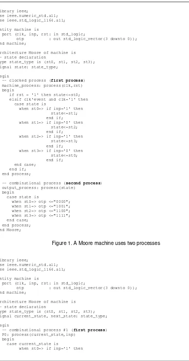
The state machine usually works in two phases. In the first phase, the new state is calculated, and in the second phase the new state is sampled into a register. In general, for describing a state machine in VHDL, an enumeration type for the states can be declared, and process statements can be utilized for the state registers and the next-state logics. Other way uses three different processes: one to decode next state, one to assign current state and one for the output signals [27, 33, 35, 39, 40]. In order to be more readable and easier to debug, this thesis introduces synchronization-evolution-action approach as the way of describing as state machine in VHDL.
d. Synchronization : a process to synchronize the state transition at every clock cycle i.e. the state transition will only occur at the rising edge of the designated clock. e. Evolution : to describe the condition of the state transition, from current state to
another state
library ieee;
use ieee.numeric_std.all; use ieee.std_logic_1164.all;
Entity machine is
port (clk, inp, rst: in std_logic;
otp : out std_logic_vector(3 downto 0)); end machine;
Architecture Moore of machine is -- state declaration
type state_type is (st0, st1, st2, st3); signal state: state_type;
begin
-- clocked process (first process) machine_process: process(clk,rst) begin
if rst = '1' then state<=st0; elsif clk'event and clk='1' then case state is
when st0=> if inp='1' then state<=st1; end if;
when st1=> if inp='0' then state<=st2; end if;
when st2=> if inp='1' then state<=st3; end if;
when st3=> if inp='0' then state<=st0; end if; end case;
end if; end process;
-- combinational process (second process) output_process: process(state)
begin
case state is
when st0=> otp <="0000"; when st1=> otp <="1001"; when st2=> otp <="1100"; when st3=> otp <="1111"; end case;
end process; end Moore;
Figure 1. A Moore machine uses two processes
library ieee;
use ieee.numeric_std.all; use ieee.std_logic_1164.all;
Entity machine is
port (clk, inp, rst: in std_logic;
otp : out std_logic_vector(3 downto 0)); end machine;
Architecture Moore of machine is -- state declaration
type state_type is (st0, st1, st2, st3); signal current_state, next_state: state_type;
begin
-- combinational process #1 (first process) P0: process(current_state,inp)
next_state<=st1; end if;
when st1=> if inp='0' then next_state<=st2; end if;
when st2=> if inp='1' then next_state<=st3; end if;
when st3=> if inp='0' then next_state<=st0; end if;
end case; end process;
P1: process(clk,rst) -- second process
begin
if rst = '1' then current_state<=st0; -- reset state elsif clk'event and clk='1' then
current_state<=next_state; end if;
end process;
-- combinational process #2 (third process) P2: process(current_state)
begin
case current_state is when st0=> otp <="0000"; when st1=> otp <="1001"; when st2=> otp <="1100"; when st3=> otp <="1111"; end case;
end process; end Moore;
Figure 2. A Moore machine uses three processes
library ieee;
use ieee.numeric_std.all; use ieee.std_logic_1164.all;
Entity machine is
port (clk, inp, rst: in std_logic;
otp : out std_logic_vector(3 downto 0)); end machine;
Architecture Moore of machine is -- state declaration
type state is (st0, st1, st2, st3); signal current_state, next_state : state;
begin
synchronization:
process (clk, rst) is begin
if rst = '1' then current_state <= st0; elsif rising_edge(clk) then current_state <= next_state; end if;
end process;
evolution:
process (inp, current_state) is begin
--default state evolution next_state <= current_state;
case current_state is
next_state <=st1; end if;
when st1=> if inp='0' then next_state <=st2; end if;
when st2=> if inp='1' then next_state <=st3; end if;
when st3=> if inp='0' then next_state <=st0; end if;
end case; end process;
action:
process (current_state) is begin
case current_state is when st0=> otp <="0000"; when st1=> otp <="1001"; when st2=> otp <="1100"; when st3=> otp <="1111"; end case;
end process;
end Moore;
Figure 3. A Moore machine uses Synchronization-evolution-action approach
library ieee;
use ieee.numeric_std.all; use ieee.std_logic_1164.all;
Entity machine is
port (clk, inp, rst: in std_logic;
otp : out std_logic_vector(3 downto 0)); end machine;
Architecture Moore of machine is -- state declaration
type state is (st0, st1, st2, st3); signal current_state, next_state : state;
begin
synchronization:
process (clk, rst) is begin
if rst = '1' then current_state <= st0; elsif rising_edge(clk) then current_state <= next_state; end if;
end process;
evolution_and_action:
process (inp, current_state) is begin
--default state evolution next_state <= current_state; --default output
otp <="0000";
case current_state is
when st0=> if inp='1' then next_state <=st1;
otp <="0000";
end if;
end if;
when st2=> if inp='1' then next_state <=st3;
otp <="1100";
end if;
when st3=> if inp='0' then next_state <=st0;
otp <="1111";
end if; end case;
end process;
end Moore;
Figure 4. A Moore machine uses Synchronization-evolution-action approach: evolution and action steps are merged
In some cases, the evolution and action steps can be merged so that unnecessary register usages or latch problems can be avoided.
7. Conclusion
This paper has presented an overview of FPGA Programming. FPGA platforms and perspectives of VHDL programming, included some perspectives (execution, modelling, programming style, construction methodology and synthesis) have been presented. Finally, the synchronization-evolution-action approach in state machine is introduced.
References
[1] Monmasson E, Cirstea MN. FPGA Design Methodology for Industrial Control Systems-A Review.
IEEE Transactions on Industrial Electronics. 2007; 54(4): 1824-1842.
[2] Naouar MW, Monmasson E, Naassani AA, Slama-Belkhodja I, Patin N. FPGA-Based Current Controllers for AC Machine Drives-A Review. IEEE Transactions on Industrial Electronics. 2007; 54(4): 1907-1925.
[3] Sutikno T, Facta M. An Efficient Strategy to Generate High Resolution Three-Phase Pulse Width Modulation Signal Based on Field Programmable Gate Array. International Journal of Computer and Electrical Engineering. 2010; 2(3): 413-416.
[4] Medical Imaging Implementation Using FPGAs. White Paper: Altera Corporation. 2010.
[5] Monmasson E, Idkhajine L, Naouar MW. FPGA-based Controllers. IEEE Industrial Electronics Magazine. 2011; 5(1): 14-26.
[6] Monmasson E, Idkhajine L, Cirstea MN, Bahri I, Tisan A, Naouar MW. FPGAs in Industrial Control Applications. IEEE Transactions on Industrial Informatics. 2011; 7(2): 224-43.
[7] Gonzalez-Concejero C, Rodellar V, Alvarez-Marquina A, Icaya E, Gomez-Vilda P. An FFT/IFFT Design versus Altera and Xilinx Cores. International Conference on Reconfigurable Computing and FPGAs (ReConFig '08). 2008: 337-342.
[8] Mahdian P, Griebling M. VHDL implementation of a bidirectional interface for 3ATI avionic sub-systems. The 23rd 2004 Digital Avionics Systems Conference (DASC 04). 2004. 2: 11.C.5-.1-7. [9] Alderighi M, Casini F, D'Angelo S, Mancini M, Pastore S, Sterpone L, et al. Soft Errors in
SRAM-FPGAs: A Comparison of Two Complementary Approaches. IEEE Transactions on Nuclear Science. 2008; 55(4): 2267-2273.
[10] Richards MA. Simulation libraries for system-level design. Computer. 1995; 28(2): 76-77.
[11] Jung Uk C, Quy Ngoc L, Jae Wook J. An FPGA-Based Multiple-Axis Motion Control Chip. IEEE Transactions on Industrial Electronics. 2009; 56(3): 856-70.
[12] Drayer TH, Tront JG, Conners RW, Araman PA. A development system for creating real-time machine vision hardware using field programmable gate arrays. Proceedings of the 32nd Annual Hawaii International Conference on Systems Sciences (HICSS-32). 1999: 5.
[13] Grout I. Digital Systems Design with FPGAs and CPLDs: Elsevier Science. 2011.
[14] Mezei I, Malbasa V. Using VHDL to Improve an FPGA Based Educational Microcomputer. The International Conference on Computer as a Tool (EUROCON 2005). 2005: 799-802.
[15] IEEE Standard VHDL Language Reference Manual. IEEE Std 1076-1987. 1988:0_1.
[16] IEEE Standards Interpretations: IEEE Std 1076-1987, IEEE Standard VHDL Language Reference Manual. IEEE Std 1076/INT-1991. 1992:1.
[18] IEEE Standard VHDL Language Reference Manual - Redline. IEEE Std 1076-2008 (Revision of IEEE Std 1076-2002) - Redline. 2009:1-620.
[19] Hodges BR, Proicou MC, hatrum TC. A distributed kernel for VHDL simulation. Proceedings of the IEEE 1990 National Aerospace and Electronics Conference (NAECON 1990). 1990; 1: 215-220. [20] Cogswell MC, Wood DE. A hybrid event-simulation/cycle-simulation environment for VHDL-based
designs. 1997 Proceedings VHDL International Users' Forum. 1997: 258-263.
[21] Bui H, Tahar S. Design and synthesis of an IEEE-754 exponential function. 1999 IEEE Canadian Conference on Electrical and Computer Engineering. 1999; 1: 450-455.
[22] Agha G, Frolund S, Wooyoung K, Panwar R, Patterson A, Sturman D. Abstraction and modularity mechanisms for concurrent computing. IEEE Parallel & Distributed Technology: Systems & Applications. 1993; 1(2): 3-14.
[23] Rothermel K, Helbig T. Clock hierarchies: an abstraction for grouping and controlling media streams.
IEEE Journal on Selected Areas in Communications. 1996; 14(1): 174-184.
[24] Leong C, Bento P, Lousa P, Joao N, Rego J, Rodrigues P, et al. Design and test issues of an FPGA based data acquisition system for medical imaging using PEM. IEEE Transactions on Nuclear Science. 2006; 53(3): 761-769.
[25] Brackenbury LEM, Plana LA, Pepper J. System-on-Chip Design and Implementation. IEEE Transactions on Education. 2010; 53(2): 272-81.
[26] Olsen G. System design considerations for FPGA synthesis. Idea/Microelectronics Conference Record (WESCON/94). 1994: 592-595.
[27] Donzellini G, Ponta D. A bottom-up approach to digital design with FPGA. 2011 IEEE International Conference on Microelectronic Systems Education (MSE). 2011: 31-34.
[28] Jimenez J, Martin JL, Zuloaga A, Bidarte U, Arias J. Comparison of two designs for the multifunction vehicle bus. IEEE Transactions on Computer-Aided Design of Integrated Circuits and Systems. 2006; 25: 797-805.
[29] Gohringer D, Becker J. High performance reconfigurable multi-processor-based computing on FPGAs. 2010 IEEE International Symposium on Parallel & Distributed Processing, Workshops and Phd Forum (IPDPSW). 2010: 1-4.
[30] Yan Y, Zhu JG, Guo YG. Initial rotor position estimation and sensorless direct torque control of surface-mounted permanent magnet synchronous motors considering saturation saliency. IET Electric Power Applications. 2008; 2(1): 42-8.
[31] Camposano R. From behavior to structure: high-level synthesis. IEEE Design & Test of Computers. 1990; 7: 8-19.
[32] Huang R, Vemuri R. PAHLS: towards run-time synthesis for FPGAs. 2005 International Conference on Field Programmable Logic and Applications. 2005: 739-740.
[33] Rawski M, Selvaraj H, Luba T, Szotkowski P. Application of symbolic functional decomposition concept in FSM implementation targeting FPGA devices. 2005 Sixth International Conference on Computational Intelligence and Multimedia Applications. 2005: 153-158.
[34] Szotkowski P, Rawski M. Symbolic Functional Decomposition Algorithm for FSM Implementation. The International Conference on Computer as a Tool (EUROCON 2007). 2007: 484-488.
[35] Giomi JC. Finite state machine extraction from hardware description languages. Proceedings of the Eighth Annual IEEE International ASIC Conference and Exhibit. 1995: 353-357.
[36] IEEE Standard VHDL Language Reference Manual. IEEE Std 1076-2008 (Revision of IEEE Std 1076-2002). 2009:c1-626.
[37] Using Arithmetic Operations and Types (VHDL). ALTERA.
[38] IEEE Standard Multivalue Logic System for VHDL Model Interoperability (Stdlogic1164). IEEE Std 1164-1993. 1993:0_1.
[39] Koster M, Teich J. (Self-)reconfigurable finite state machines: theory and implementation. Proceedings on Design, Automation and Test in Europe Conference and Exhibition. 2002: 559-566. [40] Tiwari A, Tomko KA. Saving power by mapping finite-state machines into embedded memory blocks