UNIVERSITI TEKNIKAL MALAYSIA MELAKA
SELF-DRIVING TOY CAR
This report submitted in accordance with requirement of the Universiti Teknikal Malaysia Melaka (UTeM) for the Bachelor Degree in Electrical Engineering
Technology (Industrial Automation and Robotics) with Honours
by
MUHAMMAD HAFIZ BIN MOHAMED YUNUS B071110411
901016-14-6759
i
UNIVERSITI TEKNIKAL MALAYSIA MELAKA
BORANG PENGESAHAN STATUS LAPORAN PROJEK SARJANA MUDA
TAJUK: Self-Driving Toy Car
SESI PENGAJIAN: 2014/15 Semester 1
Saya MUHAMMAD HAFIZ BIN MOHAMED YUNUS
mengaku membenarkan Laporan PSM ini disimpan di Perpustakaan Universiti Teknikal Malaysia Melaka (UTeM) dengan syarat-syarat kegunaan seperti berikut:
1. Laporan PSM adalah hak milik Universiti Teknikal Malaysia Melaka dan penulis. 2. Perpustakaan Universiti Teknikal Malaysia Melaka dibenarkan membuat salinan
untuk tujuan pengajian sahaja dengan izin penulis.
3. Perpustakaan dibenarkan membuat salinan laporan PSM ini sebagai bahan pertukaran antara institusi pengajian tinggi. atau kepentingan Malaysia sebagaimana yang termaktub dalam AKTA RAHSIA RASMI 1972)
(Mengandungi maklumat TERHAD yang telah ditentukan oleh organisasi/badan di mana penyelidikan dijalankan)
Alamat Tetap:
ii
DECLARATION
“I hereby declare that the content in this thesis is the result of my own work expect references and citations which I have clearly stated the source of origin”
Signature : ………
Name : MUHAMMAD HAFIZ BIN MOHAMED YUNUS
iii
APPROVAL
This report is submitted to the Faculty of Engineering Technology of UTeM as a partial fulfillment of the requirements for the degree of Bachelor in Electrical Engineering Technology (Industrial Automation and Robotics) with Honours. The member of the supervisory committee is as follow:
(Signature of Supervisor)
……….
iv
ABSTRAK
v
ABSTRACT
This project is about implementation of autonomous car or self-driving car for a toy car. The toy car move to the particular destination based on input of the destination coordinate from the user. The toy car is guided by using GPS module, Electronic compass and Microcontroller. The toy car basically can move autonomously by only using GPS module and Microcontroller. However, the direction of toy car movement is unknown and this makes Electronic Compass come in handy to determine the current heading of the toy car. Even though, the Electronic Compass will face new problem because of interference from the car movement and the electronic circuit, a chassis of toy car is designed to reduce the tilt error and magnetic disturbances of Electronic Compass. Meanwhile, the GPS module give inaccurate of position data when in dynamic environment and long distance travel. Both of these problems are inevitable since toy car main function is as a mobile and distance of travel is not limited to short distance only. The distribution of waypoints course for toy car is increased to solve the long distance travel issue and dynamic environment problem. These three main problems of the project are reduced and the positioning of coordination is more accurate and precise.
vi
DEDICATION
vii
ACKNOWLEDGEMENTS
Assalamualaikum wbt,
First of all, thanks to Allah Almighty for mercy and grace I can finish this project until to the end. Thanks to my supervisor En.Mohd Hanif Che Hasan never bored entertain and provide guidance. He is an efficient mentor and teaching in a transparent.
Did not forget to family and friends for their continuous encouragement and patience during the time the project start and until completed. To employees electronics stores around Melaka and KL which always give opinions and suggestions.
viii
List Of Symbols And Abbreviations xv
CHAPTER 1: INTRODUCTION 1
CHAPTER 2: LITERATURE REVIEW 5
x
CHAPTER 4: PROJECT DEVELOPMENT 36
4.1 Electrical Design 37
CHAPTER 5: RESULT AND DISCUSSION 47
5.1 The performance of the FV-M8 GPS Receiver 47
5.1.1 Accuracy of FV-M8 GPS Receiver 47
5.1.2 Unstable connection between satellite and GPS Receiver 49 5.1.3 Stable connection between satellite and GPS Receiver 50 5.2 The Deviation FV-M8 and HMC6352 in Disturbance
Environment
52
5.3 Elevation Error 54
5.4 The performance of SDTC in Dynamic Environment 56
5.4.1 Testing waypoint 56
5.5 Conclusion 61
CHAPTER 6: SUMMARY AND CONCLUSION 63
6.1 Summary 63
6.2 Conclusion 63
6.3 Recommendation 64
xi
REFERENCES 66
APPENDICES
xii
LIST OF FIGURES
FIGURE TITLE PAGE
2.1 The concept of operation of HM55B (Run et al, 2010)
8
2.2 Image processing set up (Ahsan et al 2012) 9
3.1 Flow chart work progress 17
3.2 Block diagram of guidance system 18
3.3 Circuit Schematic of SDTC 19
3.4 Simulation Circuit of SDTC 20
3.5 Component of hardware circuit of SDTC 21
3.6 FV-M8 GPS Receiver 22
3.7 GPS Locator Utility 23
3.8 HMC6352 Electronic compass module 24
3.9 Arduino Mega 2560 board 25
3.10 MG995 DC Servo motor 26
3.11 Servo motor positioning control 27
3.12 Dual 12 Volt DC Motor 28
3.13 L298N Dual Motor Driver 28
3.14 11.1 Volt Lithium Polymer Battery 29
3.15 Power Supply Unit Board 30
3.16 Self-Driving Toy Car Prototype 31
3.17 Communication between microcontroller and GPS receiver
32
3.18 Read two bytes from the HMC6352 slave 32
4.1 Design Process of SDTC 36
xiii
4.3 FV-M8 pin configuration 39
4.4 FV-M8 wiring 39
4.5 Electronic compass calibrating 40
4.6 Body Chassis of the SDTC 41
4.7 12V Dual DC motor assemble with tires and chassis
42
4.8 A DC Servo motor used for turning purpose 43
4.9 Algorithm Flow Chart 44
4.10 GPS Receiver data in Serial Monitor 46
5.1 Data of Latitude and Longitude at fix position for sixteen hours
48
5.2 Satellite Channel versus Distance at fix position for two hours
49
5.3 GPS and Compass Data during Normal and Disturbance Condition
54
5.4 Two points of coordinate 55
5.5 Elevation profiles 55
5.6 Test place at Bukit Beruang multipurpose hall 56 5.7 The graph of deviation result of distance and
heading
xiv
LIST OF TABLE
TABLE TITLE PAGE
3.1 FV-M8 Pin Description 23
3.2 Command used in HMC6352 25
3.3 The characteristic of the Arduino Mega 2560 26 3.4 NMEA GGA output description (SparkFun, 2014) 33
5.1 The sample of GPS Receiver Data in unstable condition 50 5.2 The communication between satellite and GPS
Receiver is stabilized
51
5.3 The sample of 28 data from GPS Receiver at 4 to 10 satellites
52
5.4 GPS and Compass Data during Normal and Disturbance Condition
53
5.5 Test five different number of waypoint 57
xv
LIST OF SYMBOLS AND ABREVIATIONS
SDTC - Self-Driving Toy Car MCU - Microcontroller Unit GPS - Global Positioning System
MIPS - Millions of Instruction per Second PDA - Personal Digital Assistant
UART - Universal Asynchronous Receiver Transmitter NMEA - National Marine Electronic Assosiation 12C - 2-wires Interface
SPI - Serial Peripheral Interface PWM - Pulse Width Modulation
PID - Proportional Integrater Derivative
ABS - Absolute Sensor
1
CHAPTER 1
INTRODUCTION
The self-driving car also known as an autonomous car, driverless car, drive-free car or a robot car, is a vehicle system that capable to handling vehicle by itself either fully autonomous or partially autonomous. By the definition in Oxford dictionary, the word autonomous means able to do things and make decisions without help from anyone else.
1.1 Background
As the technology keep grows, the society always looking for the best ways to facilitate daily routine. Transportation becomes important nowadays for people to travel to their desire places. The car technology exist recently is has focus on safety and satisfaction such auto-braking system, adaptive cruise control, GPS, parallel parking and other. These features need to be improved to fulfil the driver desire. As the research shows more than 90% car accident comes from the driver itself and other percentage from vehicle(mechanism) failure and environment(road conditions). There is a lot beneficial for the user in term of facilities such as facing road traffic, answer phone without need to focus on the road, blind people can drive and other advantages.
2 by Digital Compass to tell the current coordination and Global Positioning System (GPS) to know the destination place. The three elements, the input from user, the Digital Compass and GPS is feed to a microcontroller, Atmega2560, so that microcontroller can produce the output to control the movement of the SDTC.
The movement of SDTC driven by two dc motors to control the forward and reverse movement and one servo motor to control the left and right movement. The circle of microcontroller receive the input from Digital Compass and GPS, and give output to the servo motors is keep repeating until the destination place is reach.
1.2 Problem Statement
3
1.3 Objective
i. To develop self-driver car by using MCU and other electronic components. ii. To discover various communication protocol used for programming. iii. To study the data extracted from GPS receiver.
iv. To analyses GPS technology in aspect of accuracy and precision with the aid of electronic compass for navigation.
1.4 Scope
The work scope was covered the utility of GPS in aspects tracking of moving object such Self-Driving Toy Car (SDTC) and how the GPS receiver module was communicate with satellites to receive signal for position and time. The work scope was specified into several parts. Firstly, the SDTC was developed by using Arduino Uno board, a GPS Receiver module, Electronic Compass and other common electronic components so it has guidance system. Secondly, the communication protocol was included are 12C and UART by using C++ language. Thirdly, the data received by the
4
1.5 Thesis Outline
The Self-Driving Toy Car report consisted of 6 chapters for the final thesis. Each of the chapter was elaborated the literature review, theory, hardware and software that depend on the need of particular chapter.
Chapter 1 briefly describe about the introduction, problem statement, objective and scope of the thesis.
Chapter 2 is focusing on the literature review of method approach of hardware and software used in the previous research.
Chapter 3 explained the throughout process of method used to collect and analyse the data which the main focus on software and hardware.
Chapter 4 elaborated the development of the project by explained the important part that used in the hardware and software.
Chapter 5 was described about the result obtained in figure form which included the circuit simulation diagram and actual hardware.
5
CHAPTER 2
LITERATURE REVIEW
This chapter had been discussed the literature review of the earlier research. The discussion was about the problem arising in previous study and the method approach use to overcome or reduce the problem. The focus of the literature review was on the guidance system for Self-Driving Toy Car (SDTC) to work autonomously. However, the consequences of the selected method have its own strength and weakness.
2.1 Hardware
The hardware section consists of several components to create a guidance system and toy car to drive it. Some previous methods improve the guidance system with monitoring system. The comparison and contrast was focus on the controller unit, GPS module, Electronic Compass, user interface system and sensor unit.
2.1.1 Controller Unit
The microcontrollers used in the project include the 68HC11 and 80C188EB. By reduce the number of components used, its increase reliability reduce power consumption. The computation was barely handled by the on-board computer. The
program was written and stored in EPROM’s. Either floppy or hard drive was available
6 To design indoor air ship autopilot, a microcontroller Samsung's ARMS3C2440 is used. It can use multiple analogue signals, high-precision collect and process the signal of the ultrasonic sensor and the speed of the motor system. The available of UART is three so that can communicate with the wireless communication equipment and HMR3300 electronic compass, accepting information of motor speed system by Analogue to Digital conversion, has the PWM signal forms of control signal output capacity to control the steering gear, has high frequency with 200MHz at maximum and precise real time (Li, Y. and Liu, C., 2011)
The AT89C52 microcontroller provide low-power consumption, robust of a CMOS 8-bit microcomputer with the utility of 8K bytes of flash programmable. The on-chip Flash allows the program memory to be reprogrammed many times in system or by a conventional non-volatile memory programmer. The Atmel AT89C52 provides a highly-flexible and cheap product to many embedded control applications (Xi, B. and Fu, C., 2010).
The C8051F021 microcontroller is a fully integrated mixed-signal system-on-chip, it can control the connection between digital data and external input/output pins. The microcontroller has asynchronous, with full duplex UART0 and UART1, by determining the 1PPS to achieve the synchronization collection of electronic compass information and GPS information .It also has an internal clock, so only need to access timing control component in to form a stable self-excited oscillator (Jiang et al, 2010). To control the set point of PID controllers of the brake and throttle, the naive set point controller PID-based reactive controller is used. Unfortunately, the controller do not offer a firm guarantee that the car could arrive at either the correct time or correct velocity. Even though, the naive set point controller offers good performance in practice when provided with a feasible arrival time, in particular when seeded with the output like the optimization procedure (Au et al, 2012).
7 2.1.2 GPS Module
The GPS receiver are most important in the navigation system. The GARMIN 15-H was used in the project, have the function to updates the satellite signal to be sent to the GPS. The information of the GPS signal was extracted and transmitted again to the MCU by using the serial communication for every one second. Distance and direction between driverless car and destination are obtained through the calculation based on the GPS data (Run et al, 2010).
The current latitude and longitude was determined through GPS, after receive the destination latitude and longitude from user. The angle and distance between two coordinate was determine based on the four possibilities in which navigation can start after that. Two possibilities are for Y axis which is 90 and 270 degrees that decided to move either forward or backward (Riaz et al, 2009).
The Fastrax iTrax03 has 2m of positioning accuracy, portable and cheap GPS that has self-contained PNS (Chen et al, 2010).
The iTrax02 are small and low-power consumption was chose as GPS receiver. It use NMEA0183 format data and binary I-Talk format data as character string standard. The GPS receiver also has two roads of UART interface (Jiang et al, 2010).
2.1.3 Electronic Compass
The information of posture for the indoor unmanned air ship gathers from HMR3300 digital compass. It offering heading, pitch and roll that the three directions of state data. An electronic compass provide the airship posture information in indoor environment. Inertial navigation or GPS navigation was used in conventional aircraft. The latter is limited to outdoor use, while digital compass does not exists the problems. The scheme was proven feasible after a long flight test, that the airship flying has stable performance (Li, Y. and Liu, C., 2011).
8 yaw and pitch, it also update frequency 8Hz, and have serial communication port. The HMR3300 are portable, low power and cheap (Jiang et al, 2010).
Honeywell 2-axis electronic compass, HMC6352 has a heading accuracy of about
2.5°. HMC6352 was used to measures the intensity of Earth’s magnetic field and give the absolute angle value with respect to true magnetic north (Au et al, 2012).
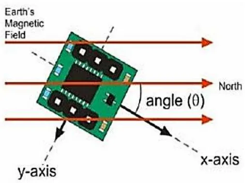
The Hitachi HM55B Compass Module was used to detect the Earth's magnetic field and thereby output the angle from the true North. So that the correct decision for turning left or right can be made by knowing the direction in front of the car. Figure 2.1 below shows the concept of operation of the electronic compass, in which the x-axis of the electronic compass indicates the long x-axis of the car body (Run et al, 2010).
Figure 2.1: The concept of operation of HM55B (Run et al, 2010)
2.1.4 User interface system