ABDUL GHAFFUR BIN MOHAMMAD MOHSIN
ABDUL GHAFFUR BIN MOHAMMAD MOHSIN
ABDUL GHAFFUR BIN MOHAMMAD MOHSIN
This Report Is Submitted In Partial Fulfillment of Requirements for the Degree of Bachelor in Electrical Engineering
(Power Electronic Actuator & Drives)
Fakulti Kejuruteraan Elektrik Universiti Teknikal Malaysia (UTeM)
“I hereby declared that I have read through this report and found that it has comply
the partial fulfillment for awarding the degree of Bachelor of Electrical Engineering
(Power Electronic Actuator & Drives)”
Signature : ………
Supervisor’s Name : ……….
“I hereby declared that this report is a result of my own work except for the
excerpts that have been cited clearly in the references.”
Signature : ………
Name : Abdul Ghaffur Bin Mohammad Mohsin
For my beloved father and mother
Mohammad Mohsin Bin Hj Mohd Sidek and Noor Riza Binti Hj Ahamad
ACKNOWLEDGEMENTS
Alhamdulilah, praise be to Allah, the Cherisher and Sustainer of world, most
Gracious, most Merciful Lord.
Praise be to Allah for enabling me to completed this gate driver for induction motor
using PIC16F877A Microcontroller project and report for my “Projek Sarjana Muda
1”.
I would like to thank P.M Ismadi Bugis as my supervisor, for his invaluable
help, support and ideas to me through achieving my “Projek Sarjana Muda 2” goals.
Her countless contributions in this project will remind forever in my mind.
During the completion, I had collaborated with many colleagues for whom I
have great regards and I want to extend my warmest thanks to all those who helped
me with my work especially Musa. Who expose me to the electronic circuit.
Finally, I would like to honor my parent, for supporting me steadfastly and
ABSTRACT
Gate driver circuit is important device for application of motor. Many
technique for control motor drives were introduce from previous , such as using
PWM (pulse width modulation), BRM (binary rate modulation) etc. Based on that
technique the proposed system are used the optocoupler device to develop the PWM.
In addition that device more simple and easy to handle the operation to produce the
required PWM. Beside that, the microcontroller PIC is used to program and control
the motor drives. So the motor load can be operated forward or reversed biased by
ABSTRAK
Litar pemacu adalah alat penting bagi menjalankan sesuatu motor. Banyak
teknik untuk menjalankan jentera motor telah diperkenalkan dari terdahulu lagi,
seperti menggunakan PWM (pemodulatan lebar denyut), BRM (modulasi kadar
perduaan) dan sebagainya. Berdasarkan teknik itu cadangan sistem digunakan alat
optocoupler untuk membangunkan PWM. Tambahan pula alat itu lebih mudah dan
mudah mengendalikan operasi untuk mengeluarkan dikehendaki PWM. Di samping
itu, mikropengawal PIC adalah digunakan untuk memprogram dan kawalan
menjalankan operasi motor. Supaya motor boleh dikendalikan ke hadapan atau
TABLE OF CONTENTS
2.1 Single Phase AC Induction Motor Characteristic 8
2.2 Rectifier Circuit 11
2.3 Device for Rectifier Circuit 13
2.4 Inverter Circuit 13
2.5 Device for Inverter Circuit 15
2.6 The PIC16F877A Microcontroller 17
2.7 Pulse Width Modulation (PWM) 20
2.8 What is the difference between Square Wave, Modified 22
Square Wave & Pure Sine Wave Inverters?
2.9 Recent Advances In Soft Switching Inverter Technology 23
3.0 METHODOLOGY
3.1 Phase A 53
3.2 Phase B 55
3.2.1 Rectifier Circuit Design 56
3.2.2 Inverter Circuit Design 57
3.2.3 Completer Gate Drive for AC Induction Motor 61
4.0 REASULT 63 4.1 Analysis on gate driver circuit 63
4.2 Expected result 63
5.0 CONCLUSION AND RECOMMENDATION
5.1 Conclusion 64
5.2 Recommendations 64
6.0 REFERENCES 67
LIST OF FIGURE
2.6 The example of output waveform for rectifier 12
2.7 Basic circuit for full bridge rectifier 12
2.8 Full bridge rectifier device 13
2.9 The example for the inverter output 14
2.10 Mosfet (BUZ10) 15
2.11 Optocoupler (HCPL3120) 16
2.12 Symbol for optocoupler 16
2.13 The Diagram of PIC16F877A and Its Pin Descriptions Diagram 18
3.1 Gate for Induction Motor Project Methodology 54
3.2 Example for 3 phase Induction Motor Control 55
3.3 Block diagram of the system 55
3.4 Circuit design for full wave bridge rectifier 56
3.5 Circuit design for full bridge inverter 58
3.6 Circuit design optocoupler device & simulation result 58
3.7 Design for snubber circuit 59
4.1 Gate driver circuit (optocoupler) 64
4.2 Inverter circuit (Mosfet) 65
CHAPTER 1.0
INTRODUCTION
1.1
BACKGROUND
Power electronics are an enabling technology and interface multiple systems with
different requirements. As such, constraints are applied to power electronics systems
by outside variables such as the load, source, environmental factors, life span
requirements, packaging and cost; all of these must be weighed and balanced to
create an optimal power electronics solution for an application. Soft-switching
topologies offer the promise of increasing power density, reducing life cycle costs,
and reducing the detrimental effects of electromagnetic interference (EMI) on any
vulnerable electronics.
Soft-switching inverters are of keen interest to researchers and product
designers alike for their many beneficial characteristics. Many papers have been
written on soft switching inverters describing the characteristics of various different
topologies. Though various topologies excel in different areas, the general family of
soft-switching inverters has several possible advantages over traditional
hard-switching inverters.
• Higher efficiency – Soft-switching inverters significantly reduce the
amount of switching loss in power semiconductor switches and make
efficiency less dependent on switching frequency.
• Harmonics and audible noise reduction – If increases in switching
above 18 kHz there is no longer any audible noise from the power
electronics.
• Increased power density – The use of smaller main switch die size is
possible because lower switching losses will result in lower device junction
temperatures for a given average load current. The efficiency improvements
ideally lead to higher power density and smaller cooling system size, but the
additional space required for auxiliary components may negate any such
benefits.
These aforementioned points are highly desirable characteristics in some applications
and considered unimportant in others. This is especially important to take into
consideration when considering the drawbacks of soft-switching converters as well
as their benefits.
Some prominent production design holdups are:
• Increased component count – soft switching inverters require additional
components which increase supply management issues, circuit layout
complexity and the overall number of possible failure points in the inverter.
• Increased cost – The soft switching inverter will likely cost more in
production than a hard switching inverter due to increased components.
• Design and control complexity – Many soft switching inverters have
complex operations that differ from a traditional inverter. This extra
complexity usually involves additional control circuitry. Additionally, the
overall design process will take longer than the traditional inverter leading to
• Reliability questions - Soft switching inverters by nature are not inherently
unreliable, but since there are no soft switching inverters in production there
is not significant information available about the long term reliability of soft
switching inverters in various applications.
Gate Driver for Induction Motor is a device that capable to generate a variable frequency modulation or variable magnitude voltage source in such a way it manage
to control induction motor operating conditions. The device operates by applying a
series of gate pulse at which the pulse width can be adjuster using PIC in accordance
to a contain modulation technique. By doing to, the controller induction motor can be
made to control at a pried timer operating condition such as speed, torque, and etc.
This project focuses on development of gate driver for single phase induction
motor. The idea behind these is that because Ac motors has a numerous advantage
are DC motor. Hence, induction motor is commonly used in industry. Ac motors is
preferred to control high horsepower compare to the DC motors. This is because AC
machine are twenty to forty percent lighter than the DC motors [9]. Besides that, AC
motors are inexpensive and requires less maintenance compare to the DC motors.
Along width advance of power electronic, controlling of AC motor drives is
becoming easier and cheaper, and mare also becoming a prime interest topic of many
researcher. The application of power electronic that used is rectifier circuit and
inverter circuit. Rectifier circuit will produce the DC voltage to the inverter from
main AC supply. While inverter circuit is used to convert back from DC voltage to
AC supply to start the AC motors. There are two type inverter that can be used in
order to control the speed and operation of AC motor: voltage source inverter and
current source inverter [9]. Mosfet is used as a switch in inverter circuit. Mosfet is
preferred because the fast switching time obtainable with them vary little with
temperature. Seconds because of the high input impedance of the device, the drive
circuitry can be of low power and also compact and simple. The driver that be used
for MOSFET in this project is BUZ10 that produce by microchip. The advantages of
a) High efficiency because of low ‘on state’ conduction losses when the
semiconductor is conducting and low ‘off state’ leakage losses when it is
blocking the source voltage.
operation of motor is more efficient, resulting in longer life, lower power dissipation
and lower overall system cost.
1. A DC machine has a commutator which is expensive and need constant
maintenance.
2. The brushes used with the commutator need periodical replacement
because constant wear tear.
So this project is expected able to overcome the internet problems of the DC
motor. In the recent past, AC motors have replaced DC drives in many applications
such as machine tools drives, paper mills, waste water treatment, conveyor and etc.
Again, in high horsepower applications solid state cycloconverter fed induction
trend is continuing eventhough the power electronic portion of these AC drives
constitutes seventy percent of their total cost [6]. AC drives have the following
advantages:
a) AC machine are twenty to forty percent lighter than the DC motors.
Besides, AC drives are inexpensive and require less maintenance compare
to the DC motors.
replace ability of hardware circuitry by implementing microcontroller
software.
In industrial field, AC motors are very popular to drives a heavy machine. The
development of gate drives device together with utilizing power switch the operation
of the induction motors can be fully controlled. This is important because, by
controlling the operation of motors energy can be reducing. In addition, the cost of
1.2 PROJECT OBJECTIVES
The main objectives of this project are to design gate driver for induction
motor control. This project consists of hardware and software. Which as describe as
follows:
1. To develop and design the pulse width modulation (PWM) using optocoupler
2. To develop and design the motor driver.
3. To design and control the motor using microcontroller.
4. To develop and design rectifier circuit and inverter circuit in order to provide
a drive system for single phase ac induction motor (speed control.
1.3 PROBLEM STATEMENT
The problem statement of this project is microcontroller is more stable
compare to the microprocessor in order to generate the pulse width modulation
(PWM) waveform. Secondly, the microcontroller circuit also simple and easy to
control. Therefore, the microcontroller is cheaper than microprocessor.
Beside that, the system build up are using optocoupler to switching the pulse
width modulation (PWM) before go throw the gate of Mosfet for inverter circuit.
And the application, function or advantage in the circuit is to:
Monitor high voltage.
Output voltage sampling for regulation.
System for control micro for power on/off.
1.3 SCOPE OF PROJECT
The scope of this project is to develop a gate drives system for single phase
AC induction motor. To achieve the objective of the project some of power
electronic circuits need to be developed. Firstly, rectifier circuit should be design.
The rectifier is used to convert AC supply to DC supply. Secondly inverter circuit
should be design in order to re-convert DC supply into AC supply. Furthermore, the
AC supply can be a variable frequency controlled through adjusting pulse duty cycle
of the PWM signal.
CHAPTER 2.0
LITERATURE REVIEW
2.1 SINGLE PHASE AC INDUCTION MOTOR CHARACTERISTIC
Induction motor is widely used in many residential, commercial, industrial and
utility applications [9]. AC induction motors transform electrical energy into mechanical
energy. It can be part of fan or pump, or connected to some other mechanical application
such as a winder and conveyor. In this project specification of the motor are single phase
AC induction motor 240V 500W. There are three basic parts of the AC induction motor
that are rotor, stator and enclosure. Stator and rotor are electrical circuits that are
Figure 2.1: Mechanism of AC induction motor
The stator is stationary electrical part of the motor. The core of the stator motor
is made up of several hundred thin laminations. These laminations are based on National
Electrical Manufactures Associations (NEMA) [9]. Stator laminations are stacked
together forming a hollow cylinder and coil of insulated wire are inserted into slot of the
stator core. The basic concept of the motor operation is electromagnetism which is each
grouping of coil together with the steel it surrounds from electromagnets [9]. The stator
windings are connected directly to the power circuit. Refer figure 2.2.
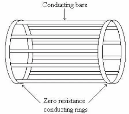
The rotor of the AC induction motor is the rotating part of the electromagnetic
circuit. The rotor is divided into two types that are squirrel cage and wound rotor.
However, the most common type of rotor is squirrel cage. This is because it is low cost,
simple, robust and low maintenance. Refer figure 2.3 and 2.4.
Figure 2.3: The rotor of AC induction motor
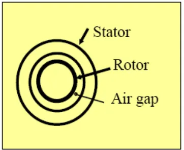
The enclosure consist of a frame of yoke and two ends bracket or bearing
housing. The stator mounted inside the frame and the rotor fits inside the stator with a
slight air gap separating it from the stator. There is no direct physical connection
between the rotor and stator. The enclosure also protecting the electrical and operating
parts of the motor from harmful effects of the environment in which the motor operates.
Refer figure 2.5.
Figure 2.5: Gap between stator and rotor
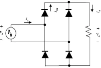
2.2 RECTIFIER CIRCUIT
Rectifier used to convert AC source to DC. There are several rectifiers that can
be used such as controlled half wave rectifier, uncontrolled half wave rectifier,
controlled full wave bridge rectifier and full wave center tapped bridge. Instead of using
half wave rectifier, full wave rectifier is most suitable in high power application such as
motor control. In this project, uncontrolled full wave bridge rectifier is used. The
purpose of the full wave rectifier is to produce an output that is purely DC, or the
purpose may be to produce a voltage or current waveform that has a specification DC
component, refer figure 2.6. A diode is a simplest electronics switches. It is
uncontrollable in that the on and off condition are determine by voltage and current in
purpose of the filter is to produce an output voltage which is close to purely DC.
Therefore, this DC voltage is used as voltage supply to the inverter circuit.
Figure 2.6: The example of output waveform for rectifier