ii
FUZZY LOGIC CONTROL OF AN AUTONOMOUS MOBILE ROBOT
WAN NOR SYAHIRA BINTI WAN ALI
This report is submitted in partial fulfillment of the requirements for the award of Bachelor Electronic Engineering (Computer Engineering) With Honours
Faculty of Electronic and Computer Engineering Universiti Teknikal Malaysia Melaka
iii
“I hereby declare that this report is the result of my own work except for quotes as cited in the references.
iv
“I hereby declare that I have read this report and in my opinion this report is sufficient in terms of the scope for the award of Bachelor of Electronic Engineering
(Computer Engineering) With Honours.”
v
vi
My first thanks for my supervisor, Puan Sharatul Izah Samsudin, whose constant support, patience and unbounded enthusiasm were of invaluable help. Her devotion to the needs of the students and the encouragements has made working with him a true delight. Thanks for helping me to kick start this research by providing insights and his work as reference. My sincere thankful to fellow friends in time spend sharing the similar research interests. I appreciated with the concern of helping me in enriching ideas in this project.
vii
viii
ix
1.1 Background Study 1
1.2 Problem Statement 2
1.3 Objectives 2
1.4 Scopes of project 3
1.5 Methodology 3
x
2.2 Nonholonomic Constraints on Kinematics 6 Model
2.3 Kinematic Equations 6
2.4 Control of the Kinematics Model 8
2.5 Dynamic Equations 9
2.6 Fuzzy logic 13
2.6.1 The Sugeno Method 15 2.6.2 The Mamdani Method 16 2.6.3 Comparison Between Sugeno and
Mamdani Method 17 2.6.4 Fuzzy Logic Membership Function 18 2.6.5 Fuzzy Logic Rule-base System 20 2.6.6 Fuzzy Logic Inference System 22 2.7 Fuzzy Logic Control in Matlab 24
3.1 Prove the Mathematical Model 26 3.2 Reconstruct the Tracking Controller 27 3.3 Fuzzy Logic Controller Design 27 3.4 Comparison between Mamdani’s and
Sugeno’s Method 28
4.1 Mathematical Model and the Tracking
Controller 29
xi
4.5.1 The Application of Rule Base and Membership Function Based on
Sugeno’s Method. 43
4.5.2 The Application of Similar Rule
Base of Sugeno’s Method with Different
Membership Function 44
4.5.3 The Application of Similar Membership Function of Sugeno’s Method with
Different Rule Base 45
4.5 Differentiation between Sugeno and Mamdani
Method. 48
50
51
52
53
xii
4.1 The parameter of Fuzzy Logic Controller 35
4.2 Fuzzy Rule Set 35
4.3 The values of %OS, ζ and Ts of Sugeno’s Output Waveform. 42
xiii
1.1 Basic Flowchart of the Project 4
2.1 The Autonomous Mobile Robot 5
2.2 Unicycle Mobile Robot with Xm-Ym Coordinate System 6 2.3 Unicycle Robot with Velocity Vector (v,
ω
) and angle θ 72.4 Trigonometry Theorem 7
2.5 Fuzzy Logic Control System 13
2.6 The General Description of a Fuzzy System (left) and a
Specific Fuzzy System (right). 14
2.7 Sugeno’s Method Rule Operation 16
2.8 Example of trimf and trapmf Fuzzy Membership Function 18 2.9 Example of gaussmf, gauss2mf and gbellmf Fuzzy
Membership Function. 19
2.10 Example of sigmf, dsigmf and psigmf Fuzzy Membership
Function. 20
2.11 Example of zmf, pimf and smf Fuzzy Membership Function. 20 2.12 Interpretation Diagram of Fuzzy Inference 24 3.1 Steps in Designing Fuzzy Logic Controller 27 4.1 Mathematical Model of the Tracking Controller 29
4.2 Simulink Block Diagram of the System. 30
4.3 Mobile Robot Subsystem 30
xiv
4.5 Position Error Subsystem 31
4.6 Auxilary Velocity Control 32
4.7 The subsystem of 32
4.8 The subsystem of 32
4.9 Input and Output of Sugeno Fuzzy Logic Controller 33
4.10 Sugeno’s Input Membership Function 34
4.11 Sugeno’s Output Membership Function 34
4.12 Fuzzy Rule Set in Matlab (Rule Editor) 29
4.13 Rule Viewer of the Sugeno Fuzzy Logic Controller 36 4.14 Surface Viewer of the Sugeno Fuzzy Logic Controller 37 4.15 Mamdani’s Input and Output Fuzzy Logic Controller 37 4.16 Inputs of Membership Function for Mamdani Fuzzy Logic 38
Controller
4.17 Outputs of Membership Function for Mamdani Fuzzy Logic 38 Controller
4.18 Rule Viewer of Mamdani’s Fuzzy Logic Controller 39 4.19 Surface Viewer of Mamdani’s Fuzzy Logic Controller 39 4.20 Position error and orientation error with respect to reference
values for Sugeno method. 40
4.21 The cmax value of Sugeno’s output waveform. 41
4.22 Velocity error of Sugeno’s method. 42
4.23 Position error and orientation error with respect to reference
values for Mamdani method. 43
4.24 Velocity error of Mamdani method. 44
4.25 The New Membership Function 44
4.26 Position Error with New Membership Function. 45 4.27 Velocity Error with New Membership Function. 45
4.28 New Rule Base for Mamdani’s method 46
xv
A Fuzzy Inference System 52
B Fuzzy Inference System (FIS) in Simulink 53
1
!"#$% "
Mobile robots are mechanical devices capable of moving in an environment with a certain degree of autonomy and posses nonholonomic properties caused by nonintegrable differential constraints while Autonomous robots are robots which can perform desired tasks in unstructured environments without continuous human guidance. Many kinds of robots have some degree of autonomy. Different robots can be autonomous in different ways. A high degree of autonomy is particularly desirable in fields such as space exploration, cleaning floors, mowing lawns, and waste water treatment.
2
built with fuzzy logic, and vice-versa. However, in a number of cases, conventional design methods would have been overly complex and, in many cases, might prove simpler, faster and more efficient. The key to successful use of fuzzy logic is clever combination with conventional techniques. Also, a fuzzy system is time-invariant and deterministic. Therefore any verification and stability analysis method can be used with fuzzy logic too.
Therefore, in this project, based on the Fuzzy Logic Technique, this project will develop a tracking controller for the dynamic model of a unicycle mobile robot by integrating a kinematics controller and a torque controller. The tracking controller for the dynamic model will use a control law such that the mobile robot kinematics (velocity) reach the given velocity inputs and a fuzzy logic controller provided the required torques for the actual mobile robot. Computer simulations will be done using Matlab software, confirming the performance of the tracking controller and its application to different navigation problems. The Mamdani’s approach will also be applied and differentiate with Sugeno’s method.
& '()% )*
In this project, one of the objectives is to develop a tracking controller for the dynamic model of a unicycle mobile robot by integrating a kinematics controller and a torque controller. Besides, its purpose is to simulate and differentiate between Mamdani’s method and Sugeno’s method in fuzzy logic control system.
+ !"',)- . )-)
3
approaches that can handle real world uncertainty, researchers are frequently faced in developing systems that are difficult to control.
Nowadays, there are many researchers have carried out a lot solution and design to improve the autonomous unicycle mobile robots. However, most of the research only focused on kinematics models of mobile robot. Those robots have the controlled velocity inputs, but it is not focused to the controlled problem of nonholonomic dynamic system, where forces and torques are the true input.
Therefore, this project will be done to develop a tracking controller for the dynamic model of a unicycle mobile robot by integrating a kinematics controller and a torque controller, in order to solve this problem. Since there is two methods of fuzzy logic control systems, which is Mamdani’s and Sugeno’s method, this project will also compare the performance of both methods. Matlab software will be used to analysis this project in order to confirm the performance of the tracking navigation problems and its application to different navigation problems.
/ %"0)* "1 2) !"()%
A tracking controller for the dynamic model of a unicycle mobile robot based on the Fuzzy Logic technique will be developed. Besides, computer simulations are done by using Matlab software to confirm the performance of the tracking controller and its application to different navigation problem. Lastly, the comparison between Mamdani’s method and Sugeno’s method also will be done.
3 ) 2"#","45
4
[image:18.612.155.459.144.585.2]two controllers, which is the tracking controller for the mobile robot and the Fuzzy Logic controller of the mobile robot. The overall flowchart of the methodology that is being used is shown as in Figure 1.1 below:
5
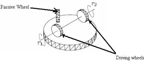
& 2) "' ,) "'"
[image:19.612.197.444.578.683.2]The term ‘autonomous robot’ has been ascribed to robotic systems to function without human supervision. [3] In this project, we assume that it is a unicycle mobile robot. The robot body is symmetrical around the perpendicular axis and the center of mass is at the geometric center of the body. It has two driving wheels fixed to the axis that passes through C and one passive oriental wheel that is placed in front of the axis and normal to it. The two fixed wheels are controlled independently by motors, and the passive wheel prevents the robot from tipping over as it moves on a plane. In what follows, we assume that the motion of passive wheel can be ignored in the dynamics of the mobile robot.
6
& & " 2"," "- % " * !. * " )-. %* "#),
Non holonomic robots are most prevalent because of their simple design and ease of control. By their nature, non holonomic mobile robots have fewer degrees of freedom than holonomic mobile robots. These few actuated degrees of freedom in non holonomic mobile robots are often independently controllable or mechanically decoupled, further simplifying the low-level control of the robot. Since they have fewer degrees of freedom, there are certain motions they cannot perform. This creates difficult problems for motion planning and implementation of reactive behaviours. Holonomic however, offer full mobility with the same number of degrees of freedom as the environment. This makes path planning easier because there aren’t constraints that need to be integrated. Implementing reactive behaviours is easy because there are no constraints which limit the directions in which the robot can accelerate. [4]
Normally, a unicycle mobile robot is said as nonholonomic because the constraints of the system impose on their kinematics. Besides, the order of the system is second order system, since the robot is nonholonomic. [6]
& + )-. % 6$. " 789
[image:20.612.183.421.524.684.2]Firstly, the Xm – Ym coordinate system is fixed to the unicycle mobile robot with C at the origin as below: [6]
7
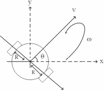
[image:21.612.229.409.154.312.2]Then, the robot is assumed to move in a linear velocity, v which is in the same direction of Xm axis and
ω
is the angular velocity of it. Figure 2.2 shows the angle,θ
is representing the heading direction of the robot.Figure 2.3: Unicycle Robot with Velocity Vector (v,
ω
) and angle θFrom figure 2.3, we can generate the coordinates by using the trigonometry theorem as below:
Figure 2.4: Trigonometry Theorem
From Figure 2.4, the polar coordinates of v and θ can be converted to the Cartesian coordinates of x and y by using the trigonometric function as:
[image:21.612.219.422.418.552.2]8
θ
=ω
We know that =( , ,θ
) for robot position Therefore, =θ
= θ
θ
sin cos Factoring…ω
θ
θ
=
1
0
0
sin
0
cos
Therefore, the planar motion of mobile robot under nonholonomic constraint of ideal
rolling condition is:
ω
θ
θ
=
1
0
0
sin
0
cos
(2.1)
& / " !", "1 2) )-. %* "#), 789
Based on the equation (2.1), the desired trajectory, q
d(t) should satisfy as
equations above: [6]
ω
θ
θ
=
1
0
0
sin
0
cos
)
(
(2.2)
The error coordinates can be defined as (2.3):
e = T
e(q
d-q) ,
9
θ
=
θ
θ
θ
θ
θ
θ
−
−
−
−
1
0
0
0
cos
sin
0
sin
cos
(2.3)
Based on Leslie Austudillo’s control objective, we know that the mobile
robot that the mobile robot can be controlled in stable if there is no error between the
real-time trajectory, q (t) and the desired trajectory, q
d(t). The controller applies
adequate torque must fulfill this condition.
Therefore, the
τ
(t) is derived as below, into specific v
c(t) that controls the
steering system.
v
c= f
c(e,v
d),
ω
=
+
+
+
+
θ θsin
cos
3 2 1(2.4)
& 3 5 .- % 6$. " 789
Most of the nonholonomic system is described by the dynamic equations
based on the Euler Lagrange formulation. The equation is shown as below:
M (q) + C (q, ) + g(q) = B(q)
τ
+ J
τ
(q)
λ
(2.5)
From the equation, M (q) is the symmetric positive-define n x n inertia
matrix. The M (q) plays important role both in the robot’s dynamic model as well as
in control design. Besides, the C (q, ) is the matrix of Cariolis and centripetal forces
for robot. In this project, the value of C (q, ) is assumed as 0, which is will be
neglected. In this project the gravitational torques, g (q) is 0 because the trajectory of
10
The dynamical equations of mobile base can be expressed in matrix form as
below:
0
0
0
0
0
0
θ
=
1
θ
θ
θ
θ
sin
sin
cos
cos
2 1τ
τ
+
θ
λ
θ
−
0
cos
sin
(2.6)
Where m is the mass of the mobile robot; I is the mass moment of inertial; r is the
radius of the wheel; R is the distance of the rear wheel;
τ
1and
τ
2are the torques of
the left and right motors; and λ is the Lagrange multipliers of constrained forces.
Hence,
C (q, ) = 0 (2.7)
g (q) = 0 (2.8)
J
τ
(q) =
−
0
cos
sin
θ
θ
(2.9)
M (q)
=
0
0
0
0
0
0
(2.10)
B (q)
−
=
θ
θ
θ
θ
τ
sin
sin
cos
cos
1
(2.11)
τ
=
2 1τ
τ
(2.12)
Solve by using equation (2.6),
θ
=
1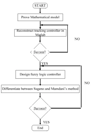
![Figure 2.2: Unicycle Mobile Robot with Xm-Ym Coordinate System [6]](https://thumb-ap.123doks.com/thumbv2/123dok/620911.74823/20.612.183.421.524.684/figure-unicycle-mobile-robot-xm-ym-coordinate.webp)