SIMULATION STUDY OF PITCHING AND ROLLING CONTROL FOR PASSANGER CAR
MOHD KHAIRUL AZWAN BIN MAMAT
I/We* have read this thesis and from my/our* opinion this thesis
is sufficient in aspects of scope and quality for awarding Bachelor of Mechanical Engineering (Automotive)
Signature : ……….
Name of Supervisor : EN MOHD HANIF BIN HARUN Date : 24 May 2010
i
SIMULATION STUDY OF PITCHING AND ROLLING CONTROL FOR PASSANGER CAR
MOHD KHAIRUL AZWAN BIN MAMAT
This report is presented in
Partial fulfillment of the requirements for the
Degree of Bachelor of Mechanical Engineering (Automotive)
Faculty of Mechanical Engineering Universiti Teknikal Malaysia Melaka
“I declare this report is on my own work except for summary and quotes that I have mentioned its sources”
Signature :………..
Name of Author : Mohd Khairul Azwan Bin Mamat
iii
ACKNOWLEDGEMENTS
Praise to Allah S.W.T from Whom i seek help and guidance and under His benevolence we exist and without his help this project could not have been accomplished.
Firstly, I would like to take this opportunity and express my gratitude to my supervisor En. Mohd Hanif bin Harun because of his guidance and encouragement for this project during this thesis period. He always appreciates whatever little progress and gives me guideline to accomplish this report. Because of him, i have achieved, and also continuously give me much inspiration by sharing his precious knowledge and experience.
v
ABSTRACT
This report presents the project in developing a mathematical modeling for vehicle dynamics study specifically for the vehicle braking and cornering condition. The derivation of 7 DOF vehicle ride model is presented. Ride model includes the degree of freedom for roll, pitch and vertical motion of the sprung mass and also vertical motion of each unsprung mass. Additional simulation programming such as CarSimEd is combined and validated to the 7 DOF ride model to study and control the performance of active suspension. The performance comparison due to pitching and rolling of vehicle between passive suspensions with active suspension will also be discussed.
ABSTRAK
Laporan ini mempersembahkan projek dalam pembentukan model matematik untuk kajian dinamik kenderaan terutamanya untuk kenderaan dalam keadaan hentian mengejut dan selekoh. Penerbitan 7 darjah pembebasan model penungangan dipersembahkan. Model penungangan mengandungi darjah kebebasan untuk kecondongan, kegolekan dan gerakan keatas kenderaan dan juga gerakan keatas bagi semua tayar. Program simulasi tambahan seperti
CarSimEd digabung dan disahkan dengan 7 darjah pembebasan membolehkan
kita untuk mengkaji dan mengawal prestasi suspensi aktif. Pembezaan prestasi kecondongan dan golekan kenderaan antara suspensi pasif dan suspensi aktif akan dibincangkan.
vii
CONTENTS
CHAPTER TITLE PAGE
DECLARATION ii
DEDICATION iii
ACKNOWLEDGEMENTS iv
ABSTRACT v
ABSTRAK vi
CONTENTS vii
LIST OF TABLES xi
LIST OF FIGURES xii
LIST OF SYMBOLS xv
CHAPTER 1 INTRODUCTION 1
1.1 Background 1
1.2 Problem Statement 2
1.3 Objective 2
1.5 Project Gantt chart 4
1.6 Project outline 6
CHAPTER II LITERATURE REVIEW 7
2.1 Theory 7
2.2 suspension 9
2.2.1 Passive suspension 9
2.2.2 Semi-active suspension 10
2.2.3 Active suspension 11
2.3 Previous study on active suspension
Control 13
2.7 previous studies on Mathematical
modeling 14
CHAPTER III METHODOLOGY 15
3.1 Modeling assumption 16
3.2 Project process flow chart 17
3.2 Equation of motion 18
3.2.1 Vehicle ride model 18
ix
3.3 PID controller design 27
3.4 Active suspension controller structure 29 3.41 Decoupling Transformation 30 3.5 Modeling with Matlab Simulink 32 3.6 Validation of 7 DOF ride model
using CarSimEd 33
3.7 Vehicle pitch and roll test 39 3.7.1 Hard cornering test 39
3.7.2 Hard braking test 41
CHAPTER IV RESULT AND DISCUSSION 43
4.1 Validation of 7 DOF Ride Model
Using CarSimEd 43
4.2 Steps steer test with active suspension 46
4.3 Hard cornering tests 49
4.4 Hard braking tests 52
CHAPTER V CONCLUSION AND RECOMMENDATION 54
5.1 Conclusion 54
REFERENCE 56
xi
LIST OF TABLES
No. TITLE PAGE
Table 1 PSM 1 Gantt chart 4
Table 2 PSM 2 Gantt chart 5
Table 3 Ziegler-Nichols tuning method 28 Table 4 Parameter for 7 DOF ride model 38
Table 5 PID for Step Steer Test 46
LIST OF FIGURES
No. TITLE PAGE
Figure 1 Rolling motion 8
Figure 2 Pitching motion 8
Figure 3 Passive suspension system 9
Figure 4 Semi active suspension 10
Figure 5 Low bandwidth or soft active suspension 11 Figure 6 High bandwidth or stiff active suspension 12 Figure 7 The result simulation in braking and cornering
using passive suspension 14
Figure 8 summary process flow for PSM I and PSM II 17 Figure 9 Free body diagram of ride model
(using passive suspension) 18 Figure 10 Free body diagrams of sprung mass 19 Figure 11 Rolling and pitching motion 20 Figure 12 Free body diagram of ride model
xiii
No. TITLE PAGE
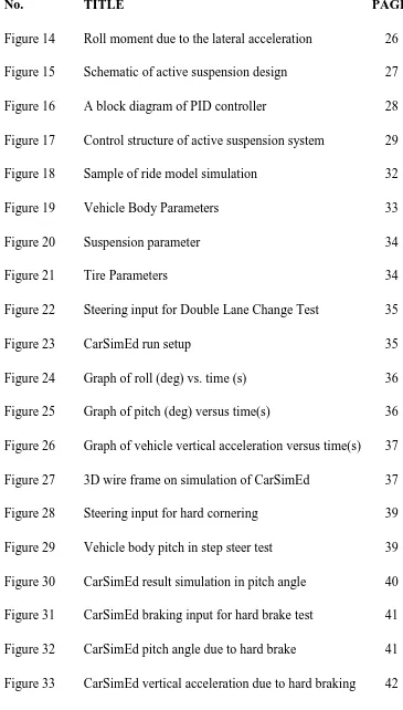
Figure 14 Roll moment due to the lateral acceleration 26 Figure 15 Schematic of active suspension design 27 Figure 16 A block diagram of PID controller 28 Figure 17 Control structure of active suspension system 29 Figure 18 Sample of ride model simulation 32 Figure 19 Vehicle Body Parameters 33
Figure 20 Suspension parameter 34
Figure 21 Tire Parameters 34
Figure 22 Steering input for Double Lane Change Test 35
Figure 23 CarSimEd run setup 35
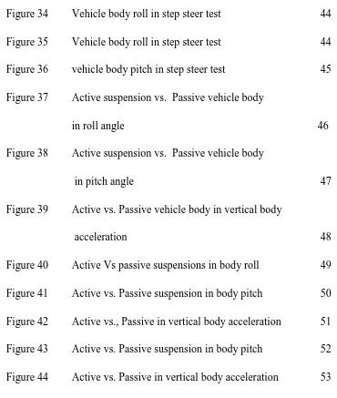
Figure 34 Vehicle body roll in step steer test 44 Figure 35 Vehicle body roll in step steer test 44 Figure 36 vehicle body pitch in step steer test 45 Figure 37 Active suspension vs. Passive vehicle body
in roll angle 46
Figure 38 Active suspension vs. Passive vehicle body
in pitch angle 47
Figure 39 Active vs. Passive vehicle body in vertical body
acceleration 48
xv
LIST OF SYMBOLS
���� = Front left suspension damping coefficient
���� = Front right suspension damping coefficient
���� = Rear left suspension damping coefficient
���� = Rear right suspension damping coefficient
��� = Front left suspension force
��� = Front right suspension force
��� = Rear left suspension force
��� = Rear right suspension force
���� = Front left actuator force
���� = Front right actuator force
���� = Rear left actuator force
���� = Rear right actuator force
h = Height of vehicle C.G.
��� = Pitch axis moment of inertia
���� = Front left suspension stiffness
���� = Front left suspension stiffness
���� = Rear left suspension stiffness
���� = Rear right suspension stiffness
���� = Front left tire stiffness
���� = Front right tire stiffness
���� = Rear left tire stiffness
���� = Rear right tire stiffness
�� = Distance of sprung mass C.G. from front axle
�� = Distance of sprung mass C.G. from rear axle
�� = Sprung mass
���� = Front left unsprung mass
���� = Front right unsprung mass
���� = Rear left unsprung mass
���� = Rear right unsprung mass
w = Track width
����R = Front left road profile
����R = Front right road profile
����R = Rear left road profile
����R = Rear right road profile
xvii
�̈� = Sprung mass vertical acceleration at body C.G.
����R = Front left sprung mass displacement
�̇���R = Front left sprung mass velocity
����R = Front right sprung mass displacement
�̇���R = Front right sprung mass velocity
����R = Rear left sprung mass displacement
�̇���R = Rear left sprung mass velocity
����R = Rear right sprung mass displacement
�̇���R = Rear right sprung mass velocity
����R = Rear left sprung mass displacement
����R = Front left unsprung mass vertical displacement
�̇���R = Front left unsprung mass vertical velocity
�̈���R = Front left unsprung mass vertical acceleration
����R = Front right unsprung mass vertical displacement
�̇���R = Front right unsprung mass vertical velocity
�̈���R = Front right unsprung mass vertical acceleration
����R = Rear left unsprung mass vertical displacement
�̇���R = Rear left unsprung mass vertical velocity
�̈���R = Rear left unsprung mass vertical acceleration
�̇���R = Rear right unsprung mass vertical velocity
�̈���R = Rear right unsprung mass vertical acceleration
� = Pitch angle at the body C.G.
�̇ = Pitch rate at the body C.G.
�̈ = Pitch acceleration at the body C.G.
� = Roll angle at the body C.G.
�̇ = Roll rate at the body C.G.
1
CHAPTER 1
INTRODUCTION
This chapter will provide the information on simulating of vehicle when pitching and rolling. The importance of these simulating will be present in this chapter. The problem statement, objective and scope of this project will also be included.
1.1 Background
A vehicle will move naturally in pitching and rolling during cornering and braking. Too much pitching and rolling will reduce ride comfort and also cause driver hard to control and maintain the direction of motion of the vehicle.
vehicle turn to the right. This motion is known as roll motion. These motions are depend on driver input on vehicle, such as accelerating and also steering.
1.2 Problem statement
The behavior of vehicle motion due to the hard braking, cornering and others road condition will affect the vehicle handling and stability of the vehicle. This vehicle behavior especially pitching and rolling during braking and cornering are being analyzed and studied. A mathematical modeling based on vehicle model is build to represent the actual vehicle behavior while cornering, braking and other road condition. This mathematical modeling is then used to study and control the pitching and rolling of vehicle during braking and cornering.
1.3 Objective
3
1.4 Project scope
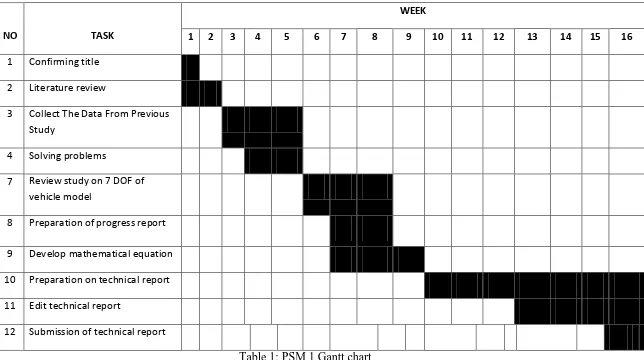
1.5 Project Gantt chart
Table 1: PSM 1 Gantt chart
NO TASK
WEEK
1 2 3 4 5 6 7 8 9 10 11 12 13 14 15 16
1 Confirming title 2 Literature review
3 Collect The Data From Previous Study
4 Solving problems
7 Review study on 7 DOF of vehicle model
8 Preparation of progress report 9 Develop mathematical equation 10 Preparation on technical report 11 Edit technical report