DOI: 10.12928/TELKOMNIKA.v14i4.4033 1284
Fault Diagnosis in Medium Voltage Drive Based
on Combination of Wavelet Transform and Support
Vector Machine
Xudong Cao*, Shaozhe Zhou, Jingze Li, Shaohua Zhang
Faulty of Geophysics and Information Engineering, China University of Petroleum, Beijing, China *Corresponding author, e-mail: [email protected]
Abstract
Nowadays, Medium Voltage Drive (MVD) has been widely applied in the field of high-powered motor speed-regulation. These types of converter use a lot of insulated gate bipolar translators (IGBTs). So it is very important to find an effective way to diagnose IGBT open-circuit faults. This study describes a method of diagnosis for IGBT open-circuit faults in MVD whose topology is cell series of multi-level. This method combines wavelet transform (WT) and support vector machine (SVM). The wavelet transform is used to extract fault features and SVM is used to classify the fault states of a single power unit. Then, the trained SVM classifier is used to scan all power units of MVD sequentially. Results of simulation on the platform of MATLAB/Simulink show that this method has a good diagnosis capability. It can diagnose the IGBT open-circuit faults of the whole inverter system, and diagnosis accuracy is up to 96%. So, this method has a good application prospect.
Keywords: Insulated gate bipolar transistors, multilevel systems, Support vector machines, Wavelet transforms
Copyright © 2016 Universitas Ahmad Dahlan. All rights reserved.
1 Introduction
In recent years, MVD has been obtained large-scale application. It has the advantages of high output voltage, low content of harmonics, low switching frequency and so on. The three-phase voltage outputs of MVD are generated by series power modules. Every power module is composed of rectifier-bridge and H-bridge. One H-bridge is composed of four IGBTs. It means that there are a lot of IGBTs which are used in the inverter. But IGBT is the flimsiest component in a MVD system. So, it is very important to know if they have problem or not for MVD’s reliability and power module replacement online technology. There always are open-circuit fault and short-circuit fault states when IGBTs are broken. As for short-circuit fault state, there is already proper way to diagnose. The voltage between collector and emitter of IGBT is often measured to figure out whether this kind of fault happened or not. But for IGBT open-circuit fault, its impact is not as big as the former. The motor may still run when IGBT open-circuit fault occur. However, the output wave of MVD will get distortion,and it will also introduce DC component and lead to increasing of harmonics, insulation failure, heating problem and so on. It even leads to some other bigger problem if this problem is not treated in a timely way [1]. There is still no proper way to deal with this kind of problem for MVD. So it is necessary to research some effective detection methods.
Vázquez-Pérez [11] proposed a fast fault detection scheme for IGBT open circuit using adaptive thresholds during the turn-on transient. This approach uses a lot of component for detection. So, it is not suited for medium voltage cascaded multilevel inverters. In [12], the author combined the wavelet analysis and the support vector to diagnose IGBT open-circuit fault. But they only analysed for two-level inverter, not for cascade multilevel converter.
In this paper, for cascade multilevel inverter system, wavelet transform is used to extract fault feature, multi-SVM is used to classify the states of IGBT fault. In time and frequency domain, the wavelet transform has good localization property. The frequency of converter’s output is variable, that is to say, it’s a non-stationary signal. So conventional Fourier transform is no longer suitable for spectrum analysis here. SVM is a kind of machine learning algorithms based on statistical theory. It can master the characteristics of the sample by studying the training data, and then classifies unknown samples. Multi-SVM is used in this paper to diagnose IGBT open-circuit fault.
2. Problem Formulation
2.1. Fault Analysis of Cascade Multilevel Inverter Circuit
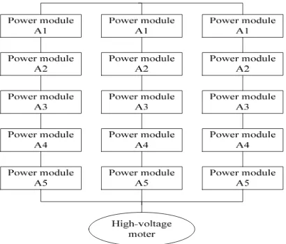
[image:2.595.196.401.441.616.2]MVD is mainly composed of phase-shifting transformer and power modules. As is shown in Figure 1, it is the power modules connection model of MVD. The advantage of this structure is that it can avoid high voltage adding to IGBT. Figure 2 shows that the power module is composed of rectifier, filter and H Bridge. The connection port R, S and T which will be connected to the secondary winding of phase-shifting transformer are three phase inputs of power module, and the port U and V are outputs. U port of one power module is connected to V port of another power module. Finally, three phase high voltage output are formed in this way.
Figure 1. Power modules connection model of MVD
Figure 2. Principle of power module
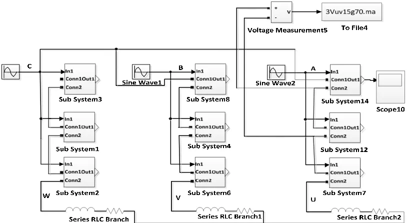
When IGBT open-circuit fault happen, the output voltage wave will distort. At the same time, the output current wave will distort too. But the output current wave is sensitive to the load. So, output voltage is selected as characteristic parameter. In this paper, simulation module of MVD is established by Simulink. For one phase output of MVD, its power module use same modulation wave. Every power module in this phase uses different carrier which phase difference is Ts/2N(N is the level of MVD and Ts is the period of MVD’s output wave). As is shown in Fig.3, the simulation module of three-level MVD is created. The module which named “To File 4” record output data. RLC module is as MVD’s load. “Sine”, “Sine1” and “Sine2” modules work as sine wave generator.
Figure 3. Simulation model of cascade three-level converter
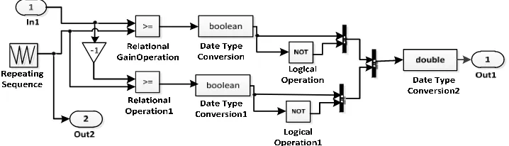
[image:3.595.87.494.417.640.2]Figure 4. Model of SPWM waveform generator
2.2. Wavelet Transform of Power Module’s Output Voltage
Wavelet transform is very sensitive to singular point of signal. The signal will show some features unlike noise’s to some extent when the output wave distortion happens. So, waveform distortion could be detected in the strong noise background if we select proper wavelet basis and scale parameter. For noise, its maxima moduli of wavelet transform reduce rapidly. So, this could raise anti-jamming capability of fault diagnosis system.
A proper wavelet basis is needed to wavelet transform. There are some common used wavelet base functions such as Morlet, Mexico, Haar, DBN, Symlet and so on. They must meet some basic performance indicators, such as vanishing moment, regularity, compactly supported, symmetry. But it is conflict for vanishing moment and compactly supported. The high rank vanishing moment means that the value of wavelet function decays to zero quickly. This brings in a high resolution ratio, but lead to supporting length growing longer. So it needs to synthesize every kind of situation.
Lipschitz index α could be used to describe signal feature of partly singularity [13]. It must meet the following formula.
|f(x0+h)-Pn(h)| ≤A*|h|α (1)
n<α≤n+1 (2)
n≥0, n∈Z (3)
A≥0, A∈Z (4)
h0≥0, h0∈Z (5)
There is a theorem which states that wavelet transform can’t detect singularity of signal if it just has n rank vanishing moment. So, the rank of wavelet basis must be high enough to get ability of detecting singularity of signal. Generally, to identify discontinuity of nth order derivative, we select at least n order disappeared regular wavelet. Some studies discover that Daubechies wavelet basis is suitable to process electronic circuit signal. Wavelet basis DB25 is selected to decompose fault signal into 8 levels. Mallat algorithm was selected to decompose the output wave of power module into 8 levels. One IGBT drive signal is disconnected at the output frequency of 50HZ.
2.3. Energy Eigenvalue of Wavelet Transform
First, evaluate energy value of wavelet decomposition coefficient. Then, put the evaluated value in a column vector which could be as eigenvector of a fault. The energy of wavelet is defined as follows:
EWj=
2 2
1
|
( ) |
( )
|
|
n j
j k
k
S t
d t
d
S(t) is the function of a signal, and EWj is the power of wavelet decomposition coefficient. Specific steps are as follows:
1. Decompose output voltage signal into 8 levels with wavelet transform. 2. Evaluate total energy of each band signal.
If the power of S (8,j) is E (8,j) (j=1,2,3,4,5,6,7,8), then
2
1
(8, )
|
|
n jk k
E
j
x
. Xjk is the amplitude of recomposed signal.
3. Construct eigenvector based on energy of every band signal.
T1=[E(8,1)/E E(8,2)/E E(8,3)/E E(8,4)/E E(8,5)/E E(8,6)/E E(8,7)/E] (7)
When some IGBTs open-circuit faults occur, there will be some changes of eigenvector. So, this eigenvector could be the input of SVM classifier.
3. Fault Diagnosis Based on Multi-SVM
SVM is a kind of machine learning algorithm which is based on statistic studying theory and structure risk minimizing principle. It has many advantages in solving small size sample, nonlinear and high dimensionality in pattern identification problems. It has a solid theoretical basis and simple mathematical model.
3.1. Principle of SVM’s Multi-class Classification
The basic algorithm of SVM is to put linear inseparable problem be mapped into high-dimensional space by the kernel function.
If there are m samples as follows:
x
1,
y
1
,
x
2,
y
2
x
m,
y
m
,
x
R
d,
y
1
,
1
(8)
In low dimensional space, linear discriminant function usually is expressed as follows:
x
w
x
b
g
(9)Equation of classification is as follows:
0
w
x
b
(10)The condition of correct classification is that it must meet the following equation:
0
1
)
(
y
iw
x
i
b
(11)
There are two stages of this method. First, we should select the optimal parameters, train the multi-SVM classifier with the eigenvectors which are extracted from wavelet decomposition. Second, use trained classifier to classify test samples. Details are as follows:
1. Select the kernel function
According to the principle of the Hilbert - Schmidt, a function can be a kernel function as long as it satisfies the Mercer condition. Kernel functions which are usually used are as follows:
Linear inner product function
x
y
x
y
K
,
T
(12)Polynomial kernel function
d
y
x
y
x
K
,
(
1
)
(13)RBF kernel function
2
exp
,
y
r
x
y
x
K
(14)
In this paper, we select the RBF kernel function which can be carried out nonlinear mapping easily.
2. Pre-treatment of sample data and training classifier
First, we select the eigenvector which can reflect the feature of faults. Then, the faults which have the same characteristics are removed. The training samples are got by normalizing the feature vector.
3. Cyclical scan the output wave data of each power module with the trained classifier In a complete cycle, all power modules could be diagnosed by the same classifier. Because control signals of IGBTs are generated by the compare of the same frequency modulation wave and the carrier. We use the classifier to cyclical scan all the power modules which we know their sequences. Then we know which IGBT and which power module occur the open-circuit fault. It is feasible to the real MVD, because every power module has a unit control board to control IGBT’s operating states. This board is also can be used to gather the value of power module’s output data and send it to the master controller which contains the classifier in it. Then IGBT open-circuit faults of the whole MVD system can be diagnosed by this classifier.
4. Simulation and Result Analysis
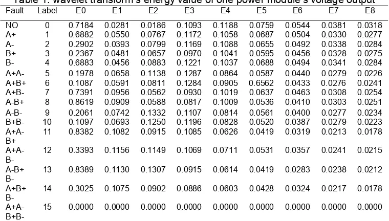
classes into one class. As we can see from the following table, the most energy focuses on first four ranks. So, we select “E0”, “E1”, “E2” and “E3” as the eigenvector.
Table 1. wavelet transform’s energy value of one power module’s voltage output
Fault Label E0 E1 E2 E3 E4 E5 E6 E7 E8 NO 0 0.7184 0.0281 0.0186 0.1093 0.1188 0.0759 0.0544 0.0381 0.0318 A+ 1 0.6882 0.0550 0.0767 0.1172 0.1058 0.0687 0.0504 0.0330 0.0277 A- 2 0.2902 0.0393 0.0799 0.1169 0.1088 0.0655 0.0492 0.0338 0.0284 B+ 3 0.2367 0.0481 0.0657 0.0970 0.1041 0.0595 0.0456 0.0328 0.0275 B- 4 0.6883 0.0456 0.0883 0.1221 0.1037 0.0688 0.0494 0.0341 0.0284 A+A- 5 0.1978 0.0658 0.1138 0.1287 0.0864 0.0587 0.0440 0.0279 0.0226 A+B+ 6 0.1087 0.0591 0.0811 0.1284 0.0905 0.6562 0.0433 0.0276 0.0241 A+B- 7 0.7391 0.0956 0.0562 0.0930 0.1019 0.0637 0.0463 0.0308 0.0254 A-B+ 8 0.8619 0.0909 0.0588 0.0817 0.1009 0.0536 0.0410 0.0303 0.0251 A-B- 9 0.2061 0.0742 0.1332 0.1107 0.0814 0.0561 0.0400 0.0277 0.0234 B+B- 10 0.1097 0.0693 0.1250 0.1196 0.0828 0.0520 0.0387 0.0279 0.0223 A+A-
B+
11 0.8382 0.1082 0.0915 0.1085 0.0626 0.0419 0.0319 0.0213 0.0178 A+A-
B-
12 0.3393 0.1156 0.1149 0.1069 0.0711 0.0531 0.0357 0.0241 0.0215 A-B+
B-
13 0.8389 0.1130 0.1307 0.0915 0.0614 0.0419 0.0283 0.0238 0.0212 A+B+
B-
14 0.3025 0.1075 0.0902 0.0886 0.0603 0.0428 0.0324 0.0217 0.0178 A+A-
B+B-
15 0.0000 0.0000 0.0000 0.0000 0.0000 0.0000 0.0000 0.0000 0.0000
The output frequency of MVD was changed from 10HZ to 70HZ. So, there are 71 samples for every type of IGBT faults. We selected the sample data of one power module as the SVM’s training data. The data of other power modules were diagnosed by this trained SVM.
The SVM’s parameters were optimized with grid-research method. Finally, the value of penalty factor was set to 32768. The parameter g was set to 0.5. The final result of IGBT open-circuit fault classification in power module whose accuracy is 96.9262% is shown as Figure 5.
Figure 5. Diagnosis result of IGBT open-circuit fault
The final diagnosis of the whole MVD is finished by this SVM classifier diagnosing all the power modules in turn. The accuracy of the remaining power modules are 96.9508%, 96.9305%, 96.7754%, 96.8433% and 96.7205%. It can be seen that the accuracy of all the power modules are high enough.
0 50 100 150 200 250 300 350 400 450 500
0 1 2 3 4 5 6 7
Sample of test set
C
lassi
fi
ca
ti
on
l
a
b
e
l
Reality and Testing Set of Power Module
[image:7.595.106.493.471.667.2]power modules are diagnosed by the trained multi-SVM classifier one by one. The simulation results demonstrate the possibility and effectiveness with this method to detect IGBT open-circuit faults in MVD. It is also adaptable for some MVDs which have different control algorithms such as vector control and voltage to frequency control, if we put the related samples to train the multi-SVM classifier.
References
[1] Yu Yong, Jiang Shengcheng. IGBT Open Circuit Fault Diagnosis Method for Inverter. Proceedings of the CSEE. 2011; 31(9): 30-35.
[2] Shang Wujun, He Zhengyou. An IGBT Output Power-Based Diagnosis of Open-Circuit Fault in Inverter. Power System Technology. 2013; 4(2013): 1104-1145.
[3] Chengguang Huang, Jin Zhao, Chaorong Wu. Data-based inverter IGBT open-circuit fault diagnosis in vector control induction motor drives. In IEEE Conference on Industrial Electronics and Applications. 2013: 1039-1044.
[4] MA Rodríguez-Blanco, A Vázquez-Pérez, L Hernández-González, A Pech-Carbonell, M MayAlarcón. IGBT Fault Diagnosis using Adaptive Thresholds during the Turn-on Transient. In IEEE International Symposium on Diagnostics for Electric Machines. Power Electronics and Drives. 2013: 241-248. [5] Estima JO, Marques CAJ. A new approach for real-time multiple open-circuit fault diagnosis in
voltage-source inverters. IEEE Transactions on Industry Applications. 2011.
[6] Gu Y, Ni F, Yang D, et al. Switching state phase shift method for three-phase current reconstruction with a single DC-link current sensor. IEEE Transactions on Industrial Electronics. 2011
[7] Chou SF, Lee CT, Ko HC, et al. A Low-voltage Ride through Method with Transformer Flux Compensation Capability of Renewable Power Grid-side Converters. IEEE Trans, on Power Electronics. 2014.
[8] Ki-Hong Kim, Yoon-Cheul Jeung, Dong-Choon Lee. LVRT Scheme of PMSG Wind Power Systems Based on Feedback Linearization. IEEE Transactions on Power Electronics. 2012.
[9] Xu You, Zhang jianyong. One-cycle Control Strategy of Three-phase PV Inverters Based on Negative Sequence Voltage Feed forward Compensation under Unbalanced Input Voltage Conditions. Proceeding of the CSEE. 2012; 12(25): 22-30.
[10] Wang Fei, Duarte JL, Hendrix MAM. Pliant active and reactive power control for grid-interactive converters under unbalanced voltage dips. IEEE Transactions on Power Electronics. 2011.
[11] Zuoliang Zhang. Fault diagnosis system of VFD based on Wavelet Transform and Neural network. Master’s degree. Chang sha: Central South University; 2008.
[12] Hu Qing, Wang Rongjie. Fault Diagnosis Technology Based on SVM in Power Electronics Circuit. Proceedings of the CSEE. 2008; 28(31): 107-111.
[13] Caseiro JAA,Cardoso AJM.Fault diagnosis on a PWM rectifier AC drive system with fault tolerance using the average current Park’s vector approach. IEEE International Electric Machines and Drives Conference. Miami, FL, USA. 2009: 695-701.
[14] Suroso Suroso, Daru Tri Nugroho, Toshihiko Noguchi. H-Bridge based Five-Level Current-Source Inverter for Grid Connected Photovoltaic Power Conditioner. TELKOMNIKA Telecommunication, Computing, Electronics and Control. 2013; 11(3): 489-494.
[15] Tang Qingquan, Yan Shichao. Open-circuit Fault Diagnosis of Transistor in Three-level
Inverter.Proceedings of the CSEE. 2008; 28(21): 26-27.
[16] A Jidin, S Sanusi, T Sutikno. Improved Output Voltage Quality using Space Vector Modulation for Multilevel Inverters. TELKOMNIKA Telecommunication, Computing, Electronics and Control. 2016; 14(2): 387-389.
[17] Stephane Mallat. A wavelet tour of signal processing. Lihua Yang. Beijing: China Machine Press. 2002: 122-142.