VELOCITY MEASUREMENTS ON FLOW AROUND A CYLINDER
Bambang Yulistiyanto
Civil and Environmental Engineering Department, Faculty of Engineering Gadjah Mada University, Jl. Grafika 2 Yogyakarta 55281
E-mail: [email protected]
ABSTRACT
If the cylinder is set in an open channel, the flow upstream will undergo a separation of the turbulent boundary layer and rolls up to form the well-known horseshoe-vortex system, which is swept around the cylinder. The flow fields around a cylinder positioned normal to the flow in an open channel have been investigated experimentally for two types of flow. An Acoustic Doppler Velocity Profiler was used to obtain instantaneously the three directions of the velocity in the flow. Results of the experiments present the vertical velocities distributions of the flow around a cylinder, showing a highly three-dimensional picture, being reasonably organized in the front and less organized in the back of the cylinder, where flow separation takes place. It also shows that a horseshoe-vortex system is established, existing of a measurable vortex with underneath a return flow. The system develops itself in the upstream corner at the nose of the cylinder and stretches around towards the downstream.
Keywords: flow fields around a cylinder, vertical velocities distributions, horseshoe-vortex
INTRODUCTION
Frown around an obstacle installed in an open channel, creates a three dimensional flow fields. The flow upstream will undergo a separation of the turbulent boundary layer and rolls up to form the well-known horseshoe-vortex system, which is swept around the cylinder. This type of flow occurs in a variety of situations, such as flow around bridge piers, around buildings and structures, and at different types of junctions.
The experiments done with airflow over round and round-nosed objects have been investigated by numerous authors ( see Baker, 1980, Eckerle and measurements were conducted by Abdul Karim Barbhuiya and Subhasish Dey (2003), for flow around a vertical semicircular cylinder attached to the sidewall and at a wing-wall abutment installed at a rectangular channel, and by Andreas Roulund at.al. (2005).
This study investigates flow fields around a cylinder by using experiment data conducted in open channel (Yulistiyanto, B., 1997).
RESEARCH METHOD
The velocity distributions in different planes upstream and downstream from a cylinder have been
performed, whose hydraulic characteristics are given in Table 1.
The experiments were performed in a 43.0 [m] long and 2.0 [m] wide tilting flume. The working section of the flume was positioned at x=16.0 [m] downstream from the entrance, where a cylinder, having a diameter of D = 22.0 [cm] and a height of H = 0.5 [m], was installed, being positioned normal to the flow. The uniform approach flow described previously ( see Graf and Yulistiyanto, 1997) was fully developed and may be considered to be two-dimensional, B/h>5, turbulent and subcritical.
Table 1. Flow variables and channel parameters
Cylinder Channel:uniform flow B = 2.0 [m]
Test D measures at different points, Q(x,y,z) or Q(r,,z), in the range of 12<r[cm]<44 and 0<[o]<180 around the cylinder; the origin was positioned in the centre of the cylinder, Q(0,0,z), whose radius is r=11[cm].
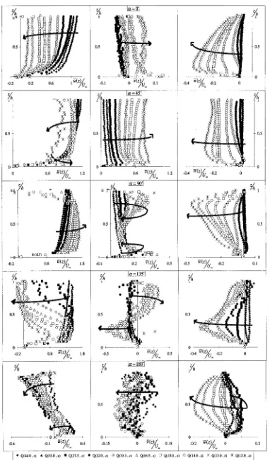
The vertical distributions of the velocities for test 2 are shown in Figure 1; for test 1 they are rather similar (see Graf and Yulistiyanto, 1998). The data are made dimensionless, using the approach velocity, U, and the local flow depth, h. The flow around the cylinder is three-dimensional, being reasonably organized at the upstream and much less organized at the downstream of the cylinder. The following can be observed:
Approaching the cylinder one observes for the longitudinal velocity profiles, u (z)/U
∞, the following:
- In the plane 0°, the profiles decrease, having more uniform distribution at value of u (z)/U∞ = 0.14 at Q(12.0,z). A flow reversal near the bed develops. - In the plane 45°, the profiles notably in the upper
region of the water depth decrease, having the maximum value below the water surface; but in the lower region there is tendency of increase.
- In the plane 90°, the profiles increase, attaining the maximum value of
u
(z)/U∞ = 1.7 at Q(12.0, z). However, some points near the surface decrease, showing the negative values at points close to the cylinder. This is possibly a consequence of the variability of the separation point at the surface, observed visually during the measurements. This point moves upstream and downstream in plane 90°. The variation of the separation point is affected by the wake vortex behind the cylinder. - In the plane 135°, the profiles first decrease,
especially in the upper region of the water depth, forming a flow reversal, and then increase closer to the cylinder.
- In the plane 180°, the profiles decrease, forming a flow reversal in the upper region of the water depth.
Approaching the cylinder one observes for the transversal velocity profiles, v(z)/U∞, the following:
- In the plane 0°, the profiles are rather uniform over the depth and their values are much smaller compared to the longitudinal ones.
- In the plane 45°, the profiles increase, having a rather constant value over the entire water depth, attaining the maximum value of v(z)/U∞ = 0.77 at Q(12.0,z).
- In the plane 90°, the profiles first increase and then decrease, notably at the upper region of the water depth and near the bed. They have a concave distribution.
- In the plane 135°, the profiles increase at the upper region of the water depth, and decrease at the lower region.
- In the plane 180°, the profiles are chaotic.
Approaching the cylinder one observes for the vertical velocity profiles, w(z)/U∞, as the following: - In the plane 0°, the profiles increase, having
always a downward direction. Its distributions have a zero value at the surface and a maximum value near the bed. The maximum downward flow is about w(z)/U∞ = 0.35 at Q ( 12.0, z), at elevation near the bed.
- In the pl ane 45°, the profiles increase, having always a downward direction, and being rather constant values from the surface to near the bed. - In the plane 90°, the profiles increase, having
always a downward direction. The maximum downward velocity near the surface, as being
w(z)/U∞= 0.47 at Q ( 12.0,z).
- In the plane 135°, the profiles increase, having downward direction.
Horizontal distributions of Velocities
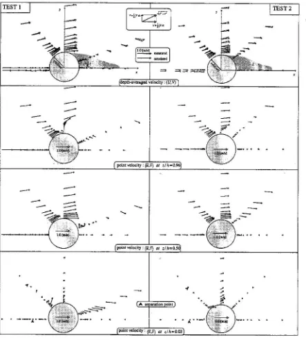
The depth-averaged velocities, U and V, obtained by the integration of the point velocity over the water depth, using the following definition:
These are presented in the first pictures of Figure 2. The shadow plane behind the cylinder is the region of the wake, calculated by the numerical model at steady state condition. Results of the depth-averaged velocity, found from the numerical simulation ( see Yulistiyanto et.al,1997) are also plotted. The figures show the flow pattern around the cylinder. Approaching the cylinder, in plane 0°, the depth-averaged velocity decrease, however in plane 45° and 90°, they increase, having the maximum values close to the cylinder. At the plane 180°, they show a velocity reversal at points near the cylinder and positive velocities at points far from the cylinder. The flow patterns in this plane, together with the plane 135°, show the existence of the wake behind the cylinder.
The point velocity at some relative elevations, at
z/h = 0.96, z/h = 0.5, and z/h= 0.03, are also presented in Figs. 2.
At z/h = 0.96, one observes that in plane 0° and 45°, the flow patterns are similar to the ones of the depth-averaged velocity. However in plane 180°, all point velocities are in the reversal direction. The flow patterns at this plane, together with the ones in plane 90° and 135°, show the existence of the wake at the surface. The size of regions affected by the wake is bigger in Test 1 than in Test 2. This indicates that the larger flow Reynolds number has a larger wake.
At z/h = 0.5, one observes that the flow pattern as well as its magnitudes are similar as the ones of the depth-averaged velocity.
At the relative elevation z/h = 0.03, one observes that the flow patterns are different from the ones of the depth-averaged velocity. At the plane 0°, 45°, and 90°, this flow pattern is formed by the existence of the horseshoe vortex in plane 0° which is then washed away downstream in plane 45° and 90°.
Velocity vectors in planes around the cylinder Further interesting observations can be made, if the velocity vectors are shown in the different vertical planes, radiating around the cylinder. The above (see Figure 1) velocity profiles,u(z) and v(z),
can be used to obtain the radial velocity, such as:
)
shown also in the insert of Figure 4.
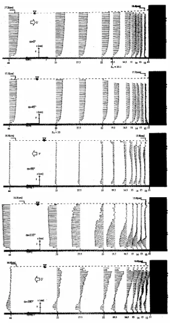
The vertical distributions of the velocities vectors,
u , and w, have been plotted in Figure 3 for test 2; the same is shown but in a three-dimensional view in Figure 4 for test 1. The following is to be observed: - In the plane = 0o : unidirectional flow is
towards the cylinder diminishing in intensity and getting more and more two-directional, first in the upper layers and subsequently over the entire flow depth; a vertical downward flow in front of the cylinder is noticed and close to the base of the cylinder a flow reversal in the lowest layers is then evident.
- In the plane = 45o: the same as in the plane = 0o is observed, but everything gets more pronounced, notably the flow reversal and the downward flow in front of the cylinder.
- In the plane = 90o : flow is away from the cylinder, diminishing in intensity and getting more and more unidirectional; very close to the cylinder and over the entire depth a flow reversal is evident, notably in test 1.
- In the plane =135o : flow is in the zone of separation and the wake of the cylinder manifests itself; a strong flow reversal is seen closer to the cylinder and only far from the cylinder the flow becomes gradually unidirectional; in the lower layers the flow away is strong, while in the upper layers the flow is directed towards the cylinder. - In the plane = 180o: the flow pattern is rather
similar to the one observed for the plane =135o.
As can be seen in the planes of approach, ( = 0o and
= 45o, the flow moves into a region of an adverse pressure gradient, created by the cylinder. Consequently the bottom layers start to separate and climb up along a shear layer, beginning at the point of separation, Sv (see Figure 3). Underneath this
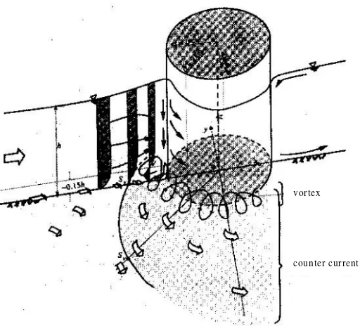
shear layer, in the bottom corner of the cylinder, a clockwise vortex is formed. Both incoming flow and the vortex are deflected sideways as a result of blockage by further incoming flow; they move downstream, with the axis of the vortex in the streamwise direction (see Figure 3 and Figure 4). In addition, the vertical downward flow close by the cylinder, augmenting the formation of clockwise vortex, begins to form a counter-flow, also referred as mushroom vortex (see Agui et Andreopoulos,
the entire flow depth. Flow far downstream of the cylinder becomes again unidirectional.
Figure 4. Three dimensional representation of flow, in planes around the cylinder, for Test 1.
Figure 5. Scheme of the horseshoe-vortex system
vortex
CONCLUSION
A schematic representation, given with Fig. 5, shall serve as a summary of our most important findings: - Measurements of the instantaneous velocity
upstream and around a cylinder are reported for fully developed turbulent open-channel flow at
ReD10 5
. This three-dimensional flow has been documented with the mean point velocity field. The measurements were made with a
non-- The vertical distributions of velocities of the flow around a cylinder show a highly three-dimensional picture, being reasonably organized in the front and less organized in the back of the cylinder, where separations flow takes place. - From the horizontal distributions of velocities, it
can be seen the existence of the horizontal wake vortex behind the cylinder. The size of regions affected by this wake is bigger in flow with larger flow Reynolds number.
- Downstream of the cylinder, the wake created by the cylinder is evident over the entire flow depth.
REFERENCES
Abdul Karim Barbhuiya and Subhasish Dey, 2003. Measurement of turbulent flow field at a vertical semicircular cylinder attached to the sidewall of a rectangular channel, Flow Measurement and Instrumentation, Volume 15, Issue 2, April 2004, Pages 87-96, Elsevier.
Abdul Karim Barbhuiya and Subhasish Dey, 2003. Velocity and turbulence at a wing-wall abutment, Sadhana Vol. 29, Part 1, February 2004, pp. 35–56, India.
Agui J.H. and Andreopoulos J., 1992. Experimental investigation of a three-dimensional boundary layer flow in the vicinity of an uprigth wall mounted cylinder, Journal of Fluids Engineering, Vol. 114, pp. 566-576.
Andreas R, B. Mutlu Sumer, F. Jorgen and M. Jess, 2005. Numerical and experimental investigation of flow and scour around a circular pile,
Journal of Fluid Mechanics, 534:351-401, Cambridge.
Eckerle W.A. and Awad J.K., 1991. Effect of free stream velocity on the three-dimensional separated flow region in front of a cylinder,
Journal of Fluids Engineering, Vol. 113, pp. 37-44.
Eckerle and Langston, 1987. Horseshoe vortex formation around a cylinder, ASME Journal of Turbomachinery, Vol. 109, Apr. pp. 278-285. Graf W.H. and M.S. Altinakar, 1993. Hydraulique
fluviale; Tome 1, Presses Poly. et Univ. Romandes, Lausanne, CH
Graf W.H. and B. Yulistiyanto, 1997. Experiments on Flow upstream of a Cylinder,PROC., XXVII Congr., Int. Assoc. Hydr. Res., Vol. 1, San Francisco, USA.
Graf W.H. and B. Yulistiyanto, 1998. Experiments on Flow around a cylinder; the velocity and vorticity fields, Journal of Hydraulic Research, Vol. 36, pp. 637-653.
Monnier J.C. and Stanislas M., 1996. Study of a horseshoe vortex by LDV and PIV,ERCOFTAC Bulletin, No. 30, pp. 19-24.
Pierce F.J. and I.K. Tree, 1990. The mean flow structure and the symmetry plane of a turbulent junction vortex, Journal of Fluids Engineering, Vol. 112, pp. 16-22.
Yulistiyanto B., Y. Zech and W.H. Graf, 1997. Free-Surface Flow Around a Cylinder : Shallow-Water Modeling with Diffusion-Dispersion,
Journal of Hydraulic Engineering, vol. 124 (no.4), pp. 419-429.