STUDY OF ROLLING CONTACT OF A CYLINDER ON A ROUGH SURFACE
WITH FINITE ELEMENT ANALYSIS
Rifky Ismail1), M. Tauviqirrahman1), Jamari2), and D.J. Schipper1) 1) Laboratory for Surface Technology and Tribology, University of Twente
Drienerlolaan 5, Enschede, The Netherlands 2) Laboratory for Engineering Design and Tribology, Mechanical Engineering Department, University of Diponegoro
Jl. Prof Sudharto, Kampus UNDIP Tembalang, Semarang Email: [email protected]
Abstract
This work presents a simulation of 2D rolling contact on a rough surface using a finite element analysis (FEA). The finite element software, ABAQUS, is used for simulating the rigid cylinder rolls over on a rough surface with different applied loads. The rough surface is considered to be elastic-perfectly plastic aluminum with strain hardening. The pure rolling and frictionless contact is assumed in the cylinder movement on a certain linear distance. The applied load is modeled as three different interferences, which results deformations and stress distributions. The static contact between a rigid indenter on a rough surface is used to validate the result by comparing the present results and the previous research results. The resulted elastic-plastic deformation and von Mises stress distribution in the simulation is reported. The increase of the applied load results the larger the deformation of the asperity on the rough surface. It also takes effect on the von Mises stress distribution. The plastic deformation area on the top of the rough surface asperity become wider as the load is increase. The deformation and stress distribution in the simulation describes the phenomenon where the engineering surface is deformed due to the rolling contact.
Keywords: rolling contact, rigid cylinder, rough surface, finite element
Introduction
The tribology science, as the one of the applied sciences in mechanical engineering, which studies friction, wear and lubrication, is concerned with what happens between two solid surfaces when they are in contact over each other. During the contact between two surfaces, any relative motion can be considered as a combination of sliding, spinning and rolling (Johnson, 1985). Rolling contact refers to the relative angular motion between two bodies in contact about an axis parallel to their common tangent plane. The engineering application of rolling contact in mechanical components can be found in rolling bearings and gears.
Contact pressure, contact stress and deformation analysis is a key for understanding and predicting fatigue and wear behavior of a rolling element (Xu and Jiang, 2002). Three types of analysis methods are often used: analytical method, semi-analytical method (SAM) and the finite element method (FEM). Analytical method in predicting the contact stress and deformation of the rolling contact has been reported by Jamari (2006) and Jamari and Schipper (2009). The analytical solution was built based on the deformation and contact pressure of the single static contact and developed to the rough surface contact deterministically. Semi-analytical approache, reported by Jacq et al. (2002), Nelias et al. (2007) and Boucly et al. (2007), was based on analytic formulae in discrete form and the quantities were then obtained by numerical computing.
A number of elastic and elastic-plastic stress analyses on rolling contact were conducted using the FEM by Bhargava and his coworkers (1985, 1989), Kulkarni et al. (1990 and 1991), Jiang et al. (2002), Xu and Jiang (2002) and Dahlberg and Alfredsson (2009). However, most of the rolling contact simulations, in two or three dimension analysis, were mostly conducted between ball against flat, ellipsoid against flat, cylinder against flat and cylinder against cylinder. Less number of publication reported the finite element analysis of rolling contact on rough surface.
summits; (iii) all asperities have same radius R but their heights very randomly; (iv) there is no interaction between asperities as they are far apart; (v) there is no bulk deformation, only the asperities deform during contact.
This paper investigates 2D rolling contact between a cylinder on a rough surface using a finite element analysis (FEA) in order to study the deformation and residual stress of the rough surface. The deformation and residual stress based on von Mises criteria are reported as function of applied loads. The deformation on the summit of cylinder results a flattening asperity on the rough surface, which performs the running-in phenomenon.
Methodology
Finite element method was constructed using the commercial software ABAQUS Version 6.5. FEM model were assembled of the rigid cylinder and rough surface where the rigid cylinder rolls over on a rough surface with different applied loads. The simulations concern in describing the line contacts (two-dimensional analysis) as the initial stage simulation of the more computationally demanding point contacts (three-dimensional). For line rolling contact, plane strain condition is assumed. Because the contact area is much smaller than the bulk size of a rolling element, a roller can be treated as a semi-infinite body.
Fig. 1. Scheme of the rolling contact model Fig. 2. Stress-strain curve (Bhowmik, 2007)
The rolling contact simulation corresponds to two sequential steps, as depicted on Fig 1. First, the normal static contact of rigid cylinder of diameter, Rs= 4,76 mm is applied on the rough
surface for a specific interference, ω. On the second step, the rigid cylinder rolls over the rough surface for a linear distance, where s = 2Rs. The vertical load is maintained while the rigid cylinder
rolls over the rough surface. Three interferences, as listed on Table 1, are set as the applied normal load. The interference load is calculated by Green’s equation (2002) so that the deformation on the
rough surface occurs on elastic-plastic deformation regime. The pure rolling contact, where no coefficient of friction applied on the model, is assumed in the simulation.
The rough surface is considered to be elastic- plastic aluminum with strain hardening material behavior. The elastic modulus (E), yield stress (Y), and Poisson’s ratio (υ) are 70 GPa, 270 MPa, and 0,32, repectively. The stress versus strain curve as depicted on Fig 2, obtained from the tensile test conducted by Bhowmik (2007), is used in the model to perform the non linear elastic-plastic model. The asperity height on rough surface parameter, Zas, is 0,96 mm, the spherical tip on the summit of asperity, Ra, is 0,76 mm and pitch of the rough surface, P is 1,5 mm which control the wave length of the rough surface.
As shown in Fig. 1, the nodes at the base of the rough surface are constrained from the displacement in the X and Y direction. The nodes on the vertical side of the rough surface are constrained to move on the x direction. To capture the high stress and strain gradients near the rolling contact surface, fine mesh is used for the area near the contact surface. The mesh is very fine in the summit of asperity and it become coarser away from it.
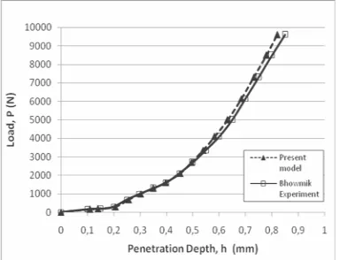
Fig. 3. Static contact model verification Fig. 4. The comparison of load versus penetration depth between present model and Bhowmik result
(2007)
Tabel 1
Applied load and resulted deformation for three different interference
Parameters ω1 ω2 ω3
Applied load (mm) 0,002 0,02 0,04
Resulted Maximum Deformation on Loading Contact (mm)
0,0019 0,0097 0,0187
Resulted Maximum Deformation on Unloading Contact (mm)
0,0007 0,0074 0,0159
Elastic recovery 61 % 24 % 15 % Fig. 5. Maximum deformation of loading and unloading contact for three different
interferences
Static Contact Verification
compare the finite element results with the Bhowmik results (2007). Figure 3 shows three dimensional rough surface which is pressed in normal direction by a rigid hemisphere. The dimension of the model considers the Bhowmik experiments (2007). The gradual normal load is applied to the rough surface. The depth of penetration of the asperities on the rough surface, regarded as deformation, is observed.
The comparison between Bhowmik experiment result and finite element simulation result can be seen on Fig. 4. The result shows good agreement between the two models until the load reach 3000 N. However, the small difference appears on the curve after the load reaches 3000 N is caused by the slight deviation on material modeling. The slight difference of the material model is critical in affecting the deformation and stress in finite element simulation (Xu and Jiang, 2002).
Results and Discussions
Deformation
The applied load and the resulted maximum deformation of the three different interferences, is listed on Table 1. As explained before that the interference is used as the applied load on the rolling contact simulation. The applied interferences are 0,002 mm, 0,02 mm and 0,04 mm, respectively and result the loading and unloading deformation as depicted in Fig. 5. The observation is made for each applied interference and it is found that the decrease of the deformation occurs on unloading contact when it is compared to the deformation at loading contact. The decrease of the deformation indicates the elastic recovery after the load is removed from the contacting asperity. The elastic recovery decreases as the interference increases. Elastic recovery can be recognized on the elastic and elastic-plastic deformation regime and the number will decrease gradually until the deformation reach fully plastic regime.
The flattening asperity of the rough surface becomes more clear on the increasing of the applied interference. The flattening asperity is related to the running-in phenomenon which is explained as localized deformation and wear at the top of asperities. Running-in on rolling contact, which occurs at an early stage of the component life, has been investigated by Jamari (2006)
(a) ω1 (b) ω2
(c) ω3
Fig. 6. Residual stress after unloading contact for three interference
Residual Stress
The strength and expected life of mechanical components can be influenced by residual stress due to its effect on contact fatigue and wear (Bijak-Zochowski and Marek, 2007). The residual stress has been obtained as a final result of the unloading process. The analysis uses von Mises stress criteria to describe the residual stress distribution of the rolling contact on the rough surface, as depicted in Figure 6. The pictures demonstrate the distribution of the residual stress in three different applied loads: ω1, ω2 and ω3, respectively. Figure 6(a) presents the residual stress for ω1, where obviously described that the residual stress only remain on the asperity. The residual stress becomes wider for ω2 and ω3, as seen in Fig. 6(b-c). The depicted residual stress also indicates the equivalent plastic strain on the rough surface after unloading contact (Bijak-Zochowski and Marek, 2007). The difference of the residual stress between Fig. 6 (b) and (c) is not significant in describing the plastic strain due to the small difference value of ω2 and ω3.
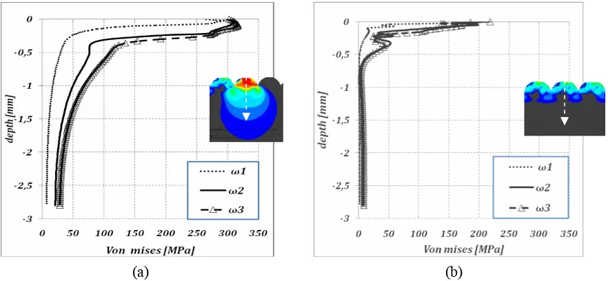
The comparison of the contact stress and residual stress as function of depth (measured from the summit of asperity) of three applied load can bee seen in Fig. 7 (a-b). Figure 7 (a) describes the contact stress (at loading contact), where the rolling cylinder reaches the summit of the observed asperity. The maximum contact stress for three different applied load is located on the subsurface, a few micron below the summit asperity surface. It indicates that the applied load works on the elastic-plastic deformation regime. When the applied load increases until fully plastic regime, the maximum von Mises stress will move closer to the asperity surface. In Fig. 7(a), after the contacting stress reaches the maximum value, it decreases dramatically as the function of the depth. The dramatic decrease of the stress also existed when a cylinders slide over the flat surface as reported by Ismail, et al. (2008 and 2009)
(a) (b)
Fig. 7. The von Mises stress distribution on (a) loading and (b) unloading rolling contact
Figure 7(b) depicts the residual stress (at unloading contact) where the rolling cylinder meet the last asperity on the rough surface and the cylinder is unloaded. The location of the maximum residual stress is on the top of the surface for three different applied loads. This phenomenon is not similar with the loading contact stress. On the unloading contact, the release of the elastic recovery on elastic-plastic deformation moves the maximum stress from the subsurface closer to the surface. The dramatic decrease of the residual stress also occurs in the unloading contact as the function of depth.
Conclusions
depicted at the highest applied load. The increase of the applied load also takes effect on the residual stress distribution based on the von Mises stress criteria. The plastic strain area on the top of the rough surface asperity become wider as the load is increase. The deformation and residual stress distribution in the simulation describes the phenomenon where the engineering surface is deformed due to the rolling contact. It will be useful in the future to continue the research by comparing the two-dimensional frictional and frictionless rolling contact.
References
1. Bhargava, V., Hahn , G. T. and Rubin, C. A., 1985, An elastic plastic finite element model of rolling contact, part 1: analysis of single contacts, ASME J. Appl. Mech. 52, pp. 67-74.
2. Bhowmik, K., 2007, Experimental and finite element study of elastic-plastic indentation of
rough surfaces, Master Thesis, Indian Institute of Science, India.
3. Bijak-Zochowski, M. and Marek, P., 1997, Residual stress in some elasto-plastic problems of rolling contact with friction, Int. J. Mech. Sci. Vol. 39. No. 1, pp. 15-32.
4. Boucly, V., Nélias, D., and Green, I., 2007, Modeling of the rolling and sliding contact between two asperities, ASME J. Tribol., 129, pp. 235-245.
5. Dahlberg, J. and Alfredsson, B., 2009, Transient rolling of cylindrical contacts with constant and linearly increasing applied slip, Wear, 266, pp. 316–326.
6. Green, I., 2005, Poisson ratio effects and crticial values in spherical and cylindrical hertzian contacts, International Journal of Applied Mechanics., Vol. 10(3), pp. 451-462.
7. Greenwood, J.A. and Williamson J.B.P., 1966, Contact of nominally flat surfaces, Proc. Royal
Soc. Lond., 295A, pp. 300-319.
8. Ham, G. L., Hahn, G. T., Rubin, C. A., and Bhargava, V., 1989, Finite element analysis of the influence of kinematic hardening in two-dimensional, repeated, rolling-sliding contact, Tribol.
Trans., 32, pp. 311-316.
9. Ismail, R., Tauviqirrahman, M., Jamari, Kiono, B.F.T., and Schipper, D.J., 2008, Finite element study of stresses due to sliding contact of a cylinder on a flat surface, Proceeding of Mechanical
Engineering National Seminar 3th, University of Petra, Surabaya, D7, 488 - 492,
10. Ismail, R., Tauviqirrahman, M., Jamari and Schipper, D.J., 2009, "Finite element analysis of sliding contact of a hard cylinder on a layered elastic-plastic solid," Proceeding of International Seminar ICAME - International Conference on Advances Mechanical Engineering, Shah Alam,
Malaysia.
11.Jacq, C., Nélias, D., Lormand, G., and Girodin, D., 2002, Development of a three-dimensional semi-analytical elastic-plastic contact code, ASME J.Tribol., 124, pp. 653-667.
12.Jamari, 2006, Running-in of rolling contacts, PhD Thesis, University of Twente, Enschede, The Netherlands.
13.Jamari, J. and Schipper, D.J., 2009, Plastic deterministic model of rolling contacts, Wear, submitted
14.Jiang, Y., Xu, B., and Sehitoglu, H., 2002, Three-dimensional elastic-plastic stress analysis of rolling contact, ASME J. Tribol., 124, pp. 699-708.
15.Johnson, K. L., 1985, Contact mechanics, Cambridge University Press.
16.Kulkarni, S., Hahn, G. T., Rubin, C. A., and Bhargarva, V., 1990, Elastoplastic finite element analysis of three-dimensional pure rolling contact above the shakedown limit, ASME J. Appl.
Mech., 58, pp. 347-353.
17.Kulkarni, S., Hahn, G. T., Rubin, C. A., and Bhargarva, V., 1991, Elasto- plastic finite element analysis of repeated three-dimensional, elliptical rolling contact with rail wheel properties,’’ASME J. Tribol., 113, pp. 434-441.
18.Kumar, A. M., Hahn, G. T., Bhargava, V., and Rubin, C. A., 1989, Elasto-plastic finite element analyses of two-dimensional rolling and sliding contact deformation of bearing steel, ASME J.
Tribol., 111, pp. 309-314.
19.Nelias D., Antaluca E., and Boucly, V., 2007, Rolling of an elastic ellipsoid upon an elastic-plastic flat, ASME J. Tribol., 129, pp. 791-800.
20.Xu, B., and Jiang, Y., 2002, Elastic-plastic finite element analysis of partial slip rolling contact,