This content has been downloaded from IOPscience. Please scroll down to see the full text.
Download details:
IP Address: 219.93.45.198
This content was downloaded on 18/12/2013 at 05:43
Please note that terms and conditions apply.
The effect of different aspect ratio and bottom heat flux
towards contaminant removal using numerical analysis
M N A Saadun1,a, C S Nor Azwadi2 Z A A Malek2, M Z A Manaf 1, M S Zakaria1 and M H M Hafidzal1
1
Faculty of Mechanical Engineering, Universiti Teknikal Malaysia Melaka, Hang Tuah Jaya, 76100 Durian Tunggal,Melaka, Malaysia
2
Faculti of Mechanical Engineering, Universiti Teknologi Malaysia, 81310 Skudai, Johor, Malaysia
E-mail: [email protected]
Abstract. Cubic Interpolated Pseudo-particle (CIP) numerical simulation scheme has been anticipated to predict the interaction involving fluids and solid particles in an open channel with rectangular shaped cavity flow. The rectangular shaped cavity is looking by different aspect ratio in modelling the real pipeline joints that are in a range of sizes. Various inlet velocities are also being applied in predicting various fluid flow characteristics. In this paper, the constant heat flux is introduced at the bottom wall, showing the buoyancy effects towards
the contaminant’s removal rate. In order to characterize the fluid flow, the numerical scheme
alone is initially tested and validated in a lid driven cavity with a single particle. The study of buoyancy effects and different aspect ratio of rectangular geometry were carried out using a MATLAB govern by Navier-Stokes equation. CIP is used as a model for a numerical scheme solver for fluid solid particles interaction. The result shows that the higher aspect ratio coupled with heated bottom wall give higher percentage of contaminant’s removal rate. Comparing with the benchmark results has demonstrated the applicability of the method to reproduce fluid structure which is complex in the system. Despite a slight deviation of the formations of vortices from some of the literature results, the general pattern is considered to be in close agreement with those published in the literature.
1. Introduction
Despite having various numbers of analytical methods of solving the Navier-Stokes Equation, it is still not sufficient enough to predict all flow models. The complexity of the flow in real engineering applications, such as in shaped pipe or combustor requires the CFD modelling to be used [1-6]. In studying the contaminant removal from rectangular shaped pipeline joints, there are also a lot of interactions between particle to particle and particle to fluid that attract the usage of CFD in solving these models. Therefore the study is focused on studying the real engineering problem of interest, which is the contaminant and deposits that accumulated in the pipeline joints. The methods in representing various sizes of gap at the joints is being modelled and represented by various aspect ratio of the cavity.
Previously, there were methods of cleaning the accumulated deposits. One of them is by using solvents. Nowadays, many researchers pointed out that the solvents used may be harmful and will
Content from this work may be used under the terms of theCreative Commons Attribution 3.0 licence. Any further distribution of this work must maintain attribution to the author(s) and the title of the work, journal citation and DOI.
cause corrosion and erosion to the pipeline material itself. The solvents used also might cause the end product to differ or contain alienated composition. Therefore the study is focused on replacing the solvents by using the natural flow to clear the deposits. Fluid flow with particle motion understanding is very important in natural and industrial applications. It is crucial for the environmental management and design and operation of such engineering equipment to comprehend the major mean particle-fluid flow phenomena, such as fluid-solid interaction and particles removal or mixing. Formation of recirculating vortices in cavities or steps can either enhance or prevent the removal of contaminant and depend on various flow parameters and characteristic of the contaminant itself. Tsorng [7] reported details experimental results on the behaviour of solid particles in lid-driven cavity flow from micro to macro size of particles. There are other researches done experimentally too [8-12]. These experimental efforts have added substantial knowledge to the state of the art of understanding on fluid-solid interaction. However, high accuracy of laser equipment together with high-speed digital image capture and data interpretation system is required to obtain reliable experimental data. Therefore as an alternative approach, many researchers considered fully computational scheme in their investigations [13-15]. From the behaviour of one particle in a lid-driven cavity flow to thousands of particles in expansion horizontal pipe has been studied in their research works sheds new hope in understanding this problem. Kosinski [16] applied the combination of continuum Navier-Stokes equations to predict
fluid flow and second Newton’s law for solid particle. Fang previously managed to predict the contaminant removal rate from a rectangular shaped cavity without heat effects [17]. Therefore this paper focused on the additional effects by the addition of heat, towards the removal rate with different aspect ratio of the cavity.
2. Physical model
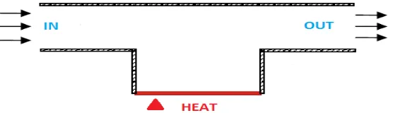
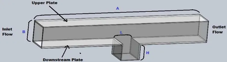
[image:3.595.159.437.526.606.2]Each of the specification and size of the model in figure 1 have been determined based on the previous modeling of the past study [18]. The length of the channel plate was A = 800mm to provide the laminar flow with the low Reynolds number of boundary layer. The thickness of the channel plate has eliminated because of the studies will done in two dimensional (2-D) analysis. For the height of the channel between the upper plate and downstream plate was B = 50mm the size is small for the height was to make sure that the flow created was the incompressible flow. Figure 1 shows that at the bottom of the cavity plate will have heat to give some heat convection effect on fluid flow in the cavity channel with interest geometry on horizontal plate.
Figure 2. The geometry and specification of the model channel. 3. Mathematical formulation
In predicting the dynamics of solid particles in shear driven cavity flow, the equation of motion for solid particle is being expressed as
p p
p f
dt dv
m
(1)wheremp, vpand fpare the mass of particle, its velocity and drag force acting on particle due to surrounding fluid respectively. According to Kosinski [16] et al, the drag force can be written as follows:
2 p p
p D p
v u v u A C
f
(2)where Ap is the projected area of solid particle and CD is the drag coefficient which is given as
p D
C
Re
24
(3)The particle’s Reynolds number in the above equation is calculated as follows
2
Rep dpuvp (4)
where dp is the diameter of solid particle.
In the computational technique, the new value of particles’ velocity,vnp1can be determined since
the pre-calculated value of vnp is known at previous time step as follows
p n p n p
p f
t v v
m
1
(5)
Then the new position of solid particle can be determined as follows
n p n
p n
p v t x
x 1
1
(6)4. Numerical simulations
There are three main governing equations that govern the flow in the channel. The three equations are namely continuity, momentum and energy equations.
a) Continuity Equation
0
y v x u (7)b) Momentum Equations
2 2 2 21
y u x u x p y u v x u u t u
(8))
(
1
2 2 2 2 c T T g y v x v y p y v v x v u t v
(9)c) Energy Equation
2 2 2 2 y T x T C k y T v x T u t T p
(10)Vorticity-stream function approach is much easier since of the velocity variable were reduced. Vorticity and vorticity-stream equations
2 2 2 2 y x
(11) xθ
Re Gr y xυ
y v x u t
2 2 2 2 2 (12)The most advantages reason for using dimensionless variables is the value is independent of dimension used, either metric or SI units. It is also to reduce the number of parameters pertaining to the physical situation and yet completely describes the behaviour of solution. Furthermore, many research papers present the variable in this way. From now on, any mentioned variable is considered in the dimensionless form. The followings list down all the dimensionless variables used in this study, and its derivation. Dimensionless variables used:
D u v D D x X u u U u v V D y Y D tu
C H C T T T T
CIP approach. In this section, CIP will be implemented base on the following advection equation hence, the advection part of NSE is:
0 Y V X U τ (13) 0 Y V X
U
(14)for the non-advection part solution the Finite Difference method should be used. It is then discretized by using Central Finite Difference. The process starts with the dimensionless momentum equation given as follows:
X
θ
Re Gr Y X Re 1 g T
2 2 2 2 2 (15)The corresponding
Xgand Yg for equation (15) areY X V X X U X θ Re Gr Y X X Re 1 T X 2 2 2 2 3 3 3 Y Y V X Y U X θ Re Gr Y Y X Re 1 T Y 2 2 2 3 3 2 3
The cubic polynomial of square grid that is used to interpolate (X,Y)within a grid cell (i. j)
− (i. j + 1) − (i + 1, j +1) − (i + 1, j) is given by
j i j i Y j i j i j i j i X j i j i j i j i j i Y Y A X A Y A X Y A X A Y A X A Y X , , , , , , , , , , ,
ˆ
]
ˆ
)
7
ˆ
6
ˆ
5
[(
ˆ
]
ˆ
4
ˆ
)
3
ˆ
2
ˆ
1
[(
)
,
(
(16)WhereX
ˆ
X
Xi,j and Y
Y
Yi,jThe following parameters is incorporated in CIP method in determining the value of
2, 1 , , 2 , , 3 , 1 , , , , 2 , , 1 , 2 , , 3 , , 1 , 1 , 1 1 , , 1 , ,
/
)
2
(
3
7
)
/(
8
6
)
/(
)
(
2
5
)
/(
8
4
/
)
2
(
3
3
)
/(
8
2
/
)
(
2
1
8
Y Y d A Y X Y d A A Y Y d A Y X Y d X d A A X X d A Y X X d A A X X d A A j i j i Y i j i i Y j i j i j i j i Y j j i i Y j X j i j i j i j i X i j i j X j i j i j i j i X i j i j i j i j i j i j i
The solution for ,X and
Y after period of
Tcan be estimated and after one time step of T
where in,j1
Ʊi, j(Xi,jUT,Yi,jVT), X
1 ,
n j
i XƱi, j and Y
1 ,
n j
i YƱi, jcan be explicitly written as
* , * , , , , * , , , , , 1 ,)
7
6
5
(
]
4
)
3
2
1
[(
j i j i Y j i j i j i j i X j i j i j i j i n j i A A A A A A A
(17) * , , , , , , 1, (3 1i j 2 2ij 2 3i j) ( 4ij 6i j ) X i j n
j i
X A A A A A
(18) * , , , , , , 1, (3 5ij 2 6ij 2 7i j) ( 4ij 2ij ) Y ij n
j i
Y A A A A A
(19) Where T V TU
,
.The following equations are used to determine the value of stream function, ,U and V velocity.
In summary, the evolution of the CIP scheme consists of three steps. The initial value of i,nj,
n j Xi, and
n j
Yi, specified at each grid points and evolves by:
1. Since the pre-advected value of i,nj, Xin,jand Yin,jare known on each grid, the constrained interpolation process can be completed according to Eqs. (17), (18) and (19).
2. After the interpolation, advection takes place, and in,*j, *
,
n j Xi and
* ,
n j
Yi are obtained.
3. The values of in,j1, Xin,1jand Yin,1j on the mesh grid are then computed from the newly advected values in step 2 by solving the non-advection phase of the governing equation. Then the interpolation and the advection processes are repeated.
5. Results and discussion
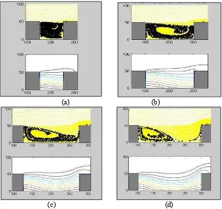
This section presents the numerical solutions of laminar forced convection heat transfer for a rectangular type of cavity with heat convection at the bottom wall. Figure 3 shows that the cavity with aspect ratio=1 produces lowest removal percentage at 8.85% followed by AR = 2 (33.6%), AR = 3 (54.25%) and AR = 4 produces highest removal rate (74.1%). For AR = 1 there is small vortex formed at top right corner, and moving towards to the centre. Since there is high number of particles packed in a small cavity, it caused the strength of the vortex weaken compared with the three others. For AR = 4 the particles waved out initially due to increased cavity width. This all is done by fixing the Reynolds number to 50 and Grashof number = 100.
(a) (b)
[image:8.595.154.478.403.707.2](c) (d)
Figure 3. Streamline and isotherm pattern for Re=50 to Gr=100 (a) AR = 1, (b) AR = 2, (c) AR = 3 and (d) AR = 4
Figure 3 also shows the isotherm pattern that indicates the buoyancy effect in the cavity. It can be seen that when the aspect ratio change the pattern of isotherm also will change but not a big difference. The pattern becomes more fluctuation or waving when the aspect ratio is higher. It have been shows in the figure 3 (c) and 3 (d). This pattern directly will influence the movement of particle in the cavity and then produce less time for particle to flush out from the cavity. The time consume for each aspect ratio are different where until it reach at some period which is called steady state. At this time (steady state), the particle totally cannot be removed from the cavity due to the weaknesses of the vortex occur. This phenomenon indicates that the vortex formation is strong enough at the early stage of flow stream.
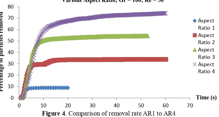
Figure 4. Comparison of removal rate AR1 to AR4
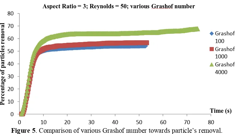
Figure 4 shows that the removal rate of higher AR generally is higher compared to lower AR and in this study. This is shown that the Reynolds number is affecting the initial unsteady state removal. It can be seen that the unsteady removal rate is much higher and it is in this region of time where the primary and secondary vortices will be formed. After the primary vortex stabilizes, then the effect of removal is due to the buoyancy force due to the temperature effect from the bottom. Generally, the higher the buoyancy force, removal rate will be higher, but specifically for higher Reynolds number, the buoyancy force and the counter-rotating vortices produced, bring the particles back to the bottom of the cavity, and this caused the removal rate at higher Reynolds number is not always higher compared to lower one at certain AR. Figure 5 shows the comparison of various Grashof number
which is make the buoyancy effect towards contaminant’s removal rate.
0 10 20 30 40 50 60 70 80
0 10 20 30 40 50 60 70
P
e
r
c
e
n
tage
o
f
p
ar
ti
c
le
s
r
e
m
o
v
e
d
Aspect Ratio 1 Aspect Ratio 2 Aspect Ratio 3 Aspect Ratio 4
Various Aspect Ratio; Gr = 100; Re = 50
Figure 5. Comparison of various Grashof number towards particle’s removal.
6. Conclusions
The simulated numerical result of the natural convection heat transfer in a square cavity at various aspect ratios shows the effectiveness of CIP-NSE method as one of the appropriate model to be applied in studying the fluid behaviour. The comparison results between the previous methods are made to validate the accuracy of the CIP-NSE method throughout this study. In this case, the CIP method is sufficiently able to solve the advection phase equation based on Navier-Stokes equations. CIP provides an alternative method in obtaining to solution for advection phase equation, however, the non-advection phase only can be solved through finite difference method. The implementation of CIP in finite difference method might not be available, thus it causing an inaccuracy for the numerical simulation. Therefore, it can be concluded that the CIP-NSE is a particular useful method to be applied in the convection heat transfer problem.
There are various variable in this study with the main one is the cavity aspect ratio, followed by different values of Reynolds and Grashof numbers. The percentage of removal is mainly affected by variation of aspect ratios, followed by Reynolds and Grashof number. The study also managed to show results with addition of temperature effects towards the rate of removal and it can be seen that the percentage of removal is increased with addition of heat for most of the cases.
Acknowledgements
The authors wish to thank to Universiti Teknikal Malaysia Melaka (UTeM) and Center of research and Innovation Management (CRIM) through research grant PJP/2012/FKM(9A)/S01084 for supporting and funding this research activities. The authors also thanks to Kementerian Pengajian Tinggi (KPT) and Universiti Teknologi Malaysia (UTM) for sponsorship study and facilities provided.
References
[1] Tahseen T A, Ishak M and Rahman M M 2013 J. Mech. Eng. Sci.4 418
[2] Mohd Adib M A H, Mohd Hasni N N T N H and Osman K 2013 J. Mech. Eng. Sci.4 496 [3] Tahseen T A, Ishak M and Rahman M M 2012 Inter. J. Automot. Mech. Eng.6 753
[4] Najiha M S, Rahman M M, Kamal M, Yusoff A R and Kadirgama K 2012 J. Mech. Eng. Sci. 3 340
[5] Wandel A P, Noor M M and Yusaf T F 2012 Inter. J. Automot. Mech. Eng.6 731
0 10 20 30 40 50 60 70 80
0 10 20 30 40 50 60 70 80
P
e
r
c
e
n
tage
o
f
p
ar
ti
c
le
s
r
e
m
o
v
al
Grashof 100 Grashof 1000 Grashof 4000
Aspect Ratio = 3; Reynolds = 50; various Grashof number
Time (s)
2nd International Conference on Mechanical Engineering Research (ICMER 2013) IOP Publishing
IOP Conf. Series: Materials Science and Engineering50(2013) 012015 doi:10.1088/1757-899X/50/1/012015
[6] Najiha M S, Rahman M M, Yusoff A R and Kadirgama K 2012 Inter. J. Automot. Mech. Eng.6 766
[7] Tsorng S J, Capart H, Lo D C, Lai J S and Young D L 2008 Behaviour of macroscopic rigid spheres in lid-driven cavity flow Intl. J. Multiphase Flow34 76-101
[8] Ilea C G, Losinski P, Hoffmann A C 2008 Three-Dimensional simulation of a dust lifting process with varying parameters Intl. J. Multiphase Flow34 869-878
[9] Azwadi C S and Takahiko T 2006 Simplified Thermal Lattice Boltzmann in Incompressible Limit Intl. J. Mod. Phys. B 20 2437-49
[10] Martys N S and Chen H 1996 Simulation of multicomponent fluids in complex three dimensional geometries by the lattice Boltzmann method Phys. Rev. A 53 743-750
[11] Frish U, Hasslacher B and Pomeau Y 1986 Lattice Gas Automata for the Navier-Stokes equation Phys. Rev. Lett.56 1505-09
[12] McNamara G and Alder B 1993 Analysis of the lattice Boltzmann treatment of hydrodynamic
Phys. A 194 218-228
[13] Ghia U, Ghia K Nand Shin C Y1982 High-Re solutions for Incompressible Flow using the Navier-Stokes Equations and a Multigrid Method J. Comp.Phys. 48 387-411
[14] Nor Azwadi C S , Attarzadeh S R 2011 An accurate numerical prediction of solid particle fluid flow in a lid-driven cavity Intl. J. Mech. 5 123-128
[15] Fang L C et. al. 1999 Transient removal of a contaminated Fluid from a cavity, Inter. J. of Heat and Fluid Flow20 605-613
[16] Kosinski P, Kosinska A and Hoffmann A C 2009 Simulation of solid particles behaviour in a driven cavity flow, Powder Tech. 191 327-339
[17] Lih-Chuan Fang 2002 Effect of mixed convection on transient hydrodynamic removal of a contaminant from a cavity Inter. J. of Heat and Mass Transfer46 2039–49